Table of Contents
Advertisement
Quick Links
®
Advanced Test Equipment Rentals
www.atecorp.com 800-404-ATEC (2832)
INSTRUCTION BOOK
®
THRULINE
RF POWER METER MODEL 4421
AND
®
THRULINE
DIRECTIONAL RF POWER SENSORS
4020 SERIES, 4027A SERIES, AND 4027F SERIES
©Copyright 2003 by Bird Electronic Corporation
Instruction Book Part Number 920-4421 Rev G
®
Thruline
is a Registered Trademark
of Bird Electronic Corporation
Advertisement
Table of Contents

Related Manuals for BIRD THRULINE 4421


Summary of Contents for BIRD THRULINE 4421
- Page 1 RF POWER METER MODEL 4421 ® THRULINE DIRECTIONAL RF POWER SENSORS 4020 SERIES, 4027A SERIES, AND 4027F SERIES ©Copyright 2003 by Bird Electronic Corporation Instruction Book Part Number 920-4421 Rev G ® Thruline is a Registered Trademark of Bird Electronic Corporation...
- Page 2 This page intentionally left blank...
-
Page 3: Safety Precautions
Safety Precautions The following are general safety precautions that are not necessarily related to any specific part or procedure and do not necessarily appear elsewhere in this publication. These precautions must be thoroughly understood and apply to all phases of operation and maintenance. Keep Away From Live Circuits Operating personnel must at all times observe normal safety regulations. - Page 4 Never attempt to connect or disconnect RF equipment from the transmission line while RF power is being applied. Leaking RF energy is a potential health hazard. WARNING The Bird 4421 contains no user-serviceable parts. Do not remove its cover. WARNING Disconnect the unit from all power sources before servicing.
- Page 5 Failure to detect a service request could result in equipment damage. CAUTION Due to the complexity of the Bird Power Sensor, field repairs beyond general maintenance should not be attempted. Removal or disturbance of the power sensor cover can result in cancellation of lifetime warranty.
- Page 6 Bird 4421 RF Power Meter EL USO DE ESTE INSTRUMENTO DE MANERA NO ESPECIFICADA POR EL FABRICANTE, PUEDE ANULAR LA PROTECCIÓN DE SEGURIDAD DEL INSTRUMENTO. BENUTZUNG WIRD DAS GERÄT AUF ANDERE WEISE VERWENDET ALS VOM HERSTELLER BESCHRIEBEN, KANN DIE GERÄTESICHERHEIT BEEINTRÄCHTIGT WERDEN.
- Page 7 ASSISTENZA TECNICA LE ISTRUZIONI RELATIVE ALL’ASSISTENZA SONO PREVISTE ESCLUSIVAMENTE PER IL PERSONALE OPPORTUNAMENTE ADDESTRATO. PER EVITARE PERICOLOSE SCOSSE ELETTRICHE NON EFFETTUARRE ALCUNA RIPARAZIONE A MENO CHE QUALIFICATI A FARLA. UNITS ARE EQUIPPED WITH RECHAREABLE BATTERIES. THESE ARE TO BE REPLACED BY AUTHORIZED SERVICE PERSONNEL ONLY!!! LAS UNIDADES VIENEN EQUIPADAS CON BATERIAS RECARGABLES.
-
Page 8: About This Manual
Bird 4421 RF Power Meter About This Manual This manual covers the Bird 4421 RF Power Meter, Bird 4020 Series Power Sensors, Bird 4027A Series Precision Power Sensors, and Bird 4027F Series Precision Filtered Power Sensors. Specific models include: 4421... -
Page 9: Table Of Contents
Table of Contents Safety Precautions ......i About This Manual......vi Introduction . - Page 10 Setup ............14 Dip Switch .
-
Page 11: Introduction
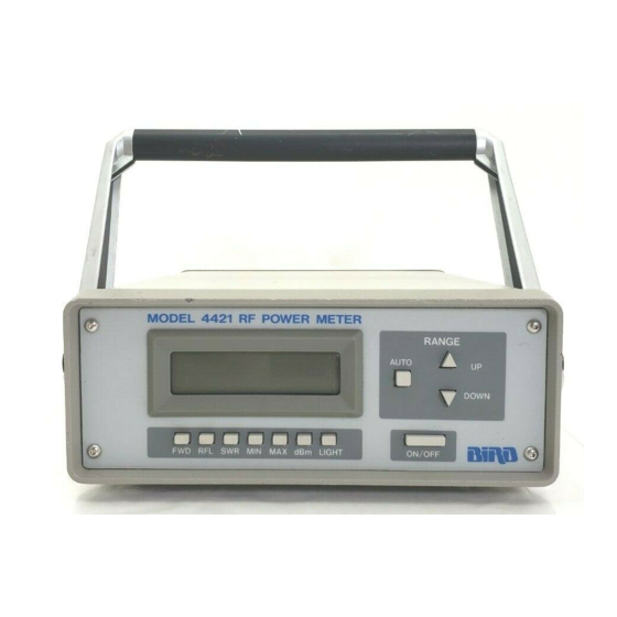
Introduction Power Meter The Bird 4421 RF Power Meter is one component of a complete RF power measurement system. An RF power sensor such as a Bird 4021 is also required. The system can be controlled with the front panel buttons, or remotely with the optional interfaces. -
Page 12: Power Sensors
Changing the sensor’s connectors will invalidate calibration data, and may reduce the maximum power rating of the unit. Bird 4020 Series Power Sensors are designed for lab or field use and 4020 Series are accurate to within ±3% of reading. -
Page 13: 4027F Series
Introduction Bird 4027F Series Power Sensors are similar to the 4027A series. 4027F Series However, additional filtering allows the 4027F to ignore harmonics of the signal being measured. The 4027F is also less sensitive to AM components of the signal. 4027F Sensors are accurate to ±1% at specified calibration frequencies and power levels. - Page 14 Bird 4421 RF Power Meter...
-
Page 15: Installation
The interface module contains electrostatic discharge (ESD) sensitive components. Failure to observe ESD precautions can cause permanent damage. To use the Bird 4421 remotely, the optional interface module must be installed (see Figure 3): 1. Unscrew and remove the interface access cover on the power meter’s rear panel. -
Page 16: Sensor Connection
Reversing these connections will cause measurement errors. Handle Operation The handle on the Bird 4421 can be set to four different positions (see Figure 4). To adjust the handle, press the center buttons on both sides. Releasing the buttons will lock the handle into position. -
Page 17: 230V Ac Power
Installation 230V AC Power Figure 5 Voltage Selection Selector Drum AC Module Door Selection Window WARNING Disconnect the unit from all power sources before servicing. The unit may be energized from multiple sources. The potential for electric shock exists. CAUTION Be sure that the 115/230 voltage selector on the 4421’s rear panel is set to the proper voltage before ac power is applied. - Page 18 Bird 4421 RF Power Meter...
-
Page 19: Operating Instructions
Chapter 3 Operating Instructions This chapter describes operator controls and indicators on the Bird 4421 RF Power Meter. If your power meter is equipped for remote operation using a GPIB or RS-232 controller, refer to the instructions in Chapter 4 or Chapter 5 respectively. -
Page 20: Error Codes
Bird 4421 RF Power Meter Error Codes The Bird 4421 displays error codes when the RF power is either below the selected range (underrange) or above the selected range (overrange). Figure 7 displays the error codes and Figure 8 lists the function limits. -
Page 21: Ieee-488 Gpib Interface
IEEE-488 GPIB Interface This chapter discusses setup of the IEEE-488 interface module and describes the IEEE commands that apply to the Bird 4421. Operators should understand IEEE standard 488-1978 and have basic computer programming skills before attempting to write any programs. -
Page 22: Description
Bird 4421 RF Power Meter Description The Bird 4421 IEEE-488 interface module is a plug-in board that can be factory or field installed. An eight-position DIP switch is used to set operational conditions and interface addresses. The current bus status is displayed on the bottom line of the display. -
Page 23: Interface Capabilities
The bottom line of the power meter’s display shows indicators Indicators describing the status of the Bird 4421 when used with the IEEE interface. These are: REMOTE: When REMOTE is displayed, the power meter is being controlled through the interface. Measurements, units of measure, and certain other parameters may be changed from a remote location. -
Page 24: Setup
Each device on the bus must have a different primary address. The Bird 4421 can be set up for manual operation while automatically Talker-Only Mode sending data to an output device (Talker-Only Mode). To do so, turn DIP switch 1 OFF and cycle the power. -
Page 25: Command Syntax
IEEE-488 GPIB Interface Command Syntax The Bird 4421 accepts two types of commands. General bus commands are commands, such as Device Clear (DCL), that apply to any IEEE interfaced device. Device-dependent commands are specific to the 4421. If an invalid command is sent to the unit, an error condition is placed in the serial poll byte and the offending command is not executed. -
Page 26: General Bus Commands
Bird 4421 RF Power Meter General Bus Commands The general bus commands supported by the IEEE-488 interface module are listed in Figure 12. The syntax for executing general commands varies among controllers; check the documentation supplied with your controller for the proper command structure. - Page 27 IEEE-488 GPIB Interface InterFace Clear (IFC) Terminates all bus activity and passes control to the system Function controller. All devices are set to talker and listener idle states. Remarks REN is set to false. REMOTE, TALK, LISTEN, and LOCAL LOCKOUT modes are cancelled, and their indicators are turned off.
- Page 28 Bird 4421 RF Power Meter Serial Polling Enable/Disable (SPE/SPD) Enables or disables the serial polling sequence. Function CAUTION During remote operation, periodically monitor the bus service request line. Failure to detect a service request could result in equipment damage. The SPE command puts all devices in serial poll mode waiting to be Remarks addressed.
-
Page 29: Device Dependent Commands
IEEE-488 GPIB Interface Device Dependent Commands The device-dependent commands used by the 4421 Power Meter are listed in Figure 15, organized by category. NOTE: The programming card also has a complete command list. Figure 15 Category Command Description IEEE-488 Forward carrier wave Measurement Device Dependent Forward dBm... - Page 30 Bird 4421 RF Power Meter Forward Carrier Wave (FC) Forward dBm (FD) Reflected Carrier Wave (RC) Reflected dBm (RD) Selects forward or reflected RF power measurement mode. Function Measurement results are returned in Watts or dBm. Remarks Standing Wave Ratio...
- Page 31 IEEE-488 GPIB Interface Range (Rxx) Selects a measurement range listed in Figure 16. Function If the selected range is outside the range of the connected power Remarks sensor, the command is ignored. Figure 16 Command Power Range Measurement Turn auto range on Ranges Turn auto range off.
- Page 32 “U” indicates underflow; the value sent is “.000”. “O” indicates overflow; the value sent is “199.9”. “N” indicates normal; the value sent is a normal on-scale reading. “4421” indicates the Bird model number. Data String Description Figure 17...
- Page 33 IEEE-488 GPIB Interface Triggers (Tx) Selects the condition which will trigger a reading (see Figure 18). Function Failure to trigger device before requesting a reading will lock the bus. Remarks T1 halts the bus until a reading is available. T0 and T1 do not set the measurement complete SRQ. T2, T3, T4, and T5 set a SRQ when the measurement is complete.
- Page 34 Bird 4421 RF Power Meter Status (Ux) Reads a status word and returns the information as a string. Set x to: Function “0” for machine status. “1” for error status. “2” for revision history. After sending the status command, a status word is sent the next time Remarks the unit is addressed to talk.
- Page 35 IEEE-488 GPIB Interface Set when no IDDCO is received. Valid Command Option Set when a self-test has been initiated Self-Test Pass by the J0 command and the test result is acceptable. Set when the self-test has failed. (This Self-Test Fail is the default condition.) Revision History Word (U2): The format of the revision history word is shown in Figure 22.
- Page 36 Bird 4421 RF Power Meter Writable Store (Wxxxxxx) Storage for six bytes of ASCII data. Function Data stored is lost when the 4421 is turned off. Remarks Data is sent back as part of the U2 status word.
-
Page 37: Rs-232 Interface
Description The Bird 4421 RS-232 interface module is a plug-in board that can be factory or field installed. An eight-position DIP switch is used to set operational conditions such as baud rate, parity, and stop bits. The current bus status is displayed on the bottom line of the display. -
Page 38: Setup
Bird 4421 RF Power Meter Setup After installing the interface module, set the DIP switches according DIP Switch to application needs and the requirements of the controller. Available settings and factory defaults are listed in Figure 24. NOTE: A DIP switch is on when pressed in at the top, and off when pressed at the bottom. -
Page 39: Talker-Only Mode
NOTE: Auto Baud is the only automatically chosen setting. Other items such as parity and stop bits must be manually selected. The Bird 4421 can be set up for manual operation while automatically Talker-Only Mode sending data to an output device (Talker-Only Mode). To do so, turn DIP switch 2 OFF and cycle the power. -
Page 40: General Bus Commands
Enables/disables software handshake XO/XF INiTialize (INT) Resets the Bird 4421 and returns it to the factory defaults. Function If INT is linked with any other command within a string, it must be Remarks separated from that command by a space. - Page 41 RS-232 Interface Baud Select (Bx) Selects a baud rate listed in Figure 26. Function When the meter recognizes a valid Bx command, its baud rate is Remarks immediately changed. (The controller is assumed to be transmitting at the new rate; otherwise sending commands would not be possible.) This command overrides the DIP switch setting.
-
Page 42: Device Dependent Commands
Bird 4421 RF Power Meter Device Dependent Commands The device-dependent commands used by the 4421 Power Meter are listed in Figure 27, organized by category. NOTE: The programming card also has a complete command list. Category Command Description Figure 27... - Page 43 RS-232 Interface Forward Carrier Wave (FC) Forward dBm (FD) Reflected Carrier Wave (RC) Reflected dBm (RD) Selects forward or reflected RF power measurement mode. Function Measurement results are returned in Watts or dBm. Remarks Standing Wave Ratio (SW) Return Loss (RL) Selects SWR or return loss match measurement mode.
- Page 44 Bird 4421 RF Power Meter Range (Rxx) Selects a measurement range listed in Figure 28. Function If the selected range is outside the range of the connected power Remarks sensor, the command is ignored. Figure 28 Command Power Range Measurement...
- Page 45 “U” indicates underflow; the value sent is “.000”. “O” indicates overflow; the value sent is “199.9”. “N” indicates normal; the value sent is a normal on-scale reading. “4421” indicates the Bird model number. Figure 29 Data String Description...
- Page 46 Bird 4421 RF Power Meter Status (Ux) Reads a status word and returns the information as a string. Set x to: Function “0” for machine status. “1” for error status. “2” for revision history. After sending the status command, a status word is sent the next time Remarks the unit is addressed to talk.
- Page 47 RS-232 Interface Set when a self-test has been initiated Self-test Pass by the J0 command and the test result is acceptable. Set when the self-test has failed. (This Self-test Fail is the default condition.) Revision History Word (U2): The format of the revision history word is shown in Figure 33.
- Page 48 Bird 4421 RF Power Meter...
-
Page 49: Maintenance
If the power sensor is malfunctioning, return it for service. CAUTION Due to the complexity of the Bird Power Sensor, field repairs beyond general maintenance should not be attempted. Removal or disturbance of the power sensor cover can result in cancellation of lifetime warranty. - Page 50 Bird 4421 RF Power Meter PROBLEM POSSIBLE CAUSE CORRECTION Power meter has no Have the batteries been charged? Recharge the batteries power Is the ac power cord connected to Connect ac power the ac line? Is the voltage selector drum set to...
-
Page 51: Functional Test
Maintenance This test determines whether the power meter or the sensor is Functional Test malfunctioning. 1. Turn the power meter off. The ON/OFF switch on the rear panel of the meter should be OFF and the ac power cable should be connected. -
Page 52: Repair
Bird 4421 RF Power Meter 12. Press dBm. “dBm” should change to “SWR”. 13. Press FWD. “SWR” should change to “FWD”. “ ” should change to “.000 W”. 14. Press LIGHT. The back-light should turn on. 15. Press LIGHT. The back-light should turn off. -
Page 53: Customer Service
Maintenance Customer Service If you need to return the unit for any reason, contact the Bird Service Center for a return authorization. All instruments returned must be shipped prepaid and to the attention of Bird Service Center. Bird Service Center... -
Page 54: Specifications
Bird 4421 RF Power Meter Specifications Bird 4421 RF Power Meter Sensor dependent Frequency Range Sensor dependent Power Range 1.0 – 199.9 max VSWR Display 0 to 40 dB max Return Loss Display ± 1 on least significant digit Display Accuracy... - Page 55 Maintenance Specifications Common to all Sensors 50 ohms nominal Impedance 1.00 to 2.00 (40.0 to 9.5 dB Return Loss) VSWR Range Approximately 2 readings/second Sampling Rate Calibration vs. frequency curve stored in nonvolatile Calibration Technique memory in each sensor. Sensor output corrected at frequency of measurement within rated range.
- Page 56 Bird 4421 RF Power Meter Bird 4020 Series RF Power Sensors Power Range 300 mW – 1 kW 4021, 4022 3 W – 10 kW 4024, 4025 Frequency Range 1.8 – 32 MHz 4021 25 MHz – 1 GHz 4022 1.5 –...
- Page 57 Maintenance CAUTION Changing the sensor’s connectors will invalidate calibration data, and may reduce the maximum power rating of the unit. Bird 4027A Series RF Power Sensors Power Range 300 mW – 1 kW 4027A12M 3 W – 9 kW 4027A25M 3 W –...
- Page 58 Bird 4421 RF Power Meter Bird 4027F Series RF Power Sensors 100 W – 10 kW Power Range Frequency Range 1.8 – 2.2 MHz 4027F2M 12 – 15 MHz 4027F10M Power Accuracy ± 1% 15 to 35 °C (59 to 95 °F) ±...
- Page 59 Maintenance IEEE-488 Interface Module Meets all IEEE Standard 488-1978 Logic Levels specifications Switch and bus selectable Modes of Operation Allows the 4421 to send to the bus keyboard- Talk Only initiated measurements only Allows the 4422 to be addressed as talker or Addressable listener under the command of an IEEE-488 bus controller...
-
Page 60: Replacement Parts
Bird 4421 RF Power Meter Replacement Parts Description Part Number Fuse, IEC (5 x 20 mm) Type T 115 Vac, 0.25 A 5A2257-10 230 Vac, 0.125 A 5A2257-7 Cord, AC Power 115 Vac 5-1286 230 Vac Harmonized 5A2416 Cable, Sensor... -
Page 61: Limited Warranty
Sensor must not be exceeded, the Sensor RF circuit must be properly terminated and the Sensor not subjected to physical abuse. Bird Electronic Corporation, at its option, will repair or replace the defective Sensor at its world Headquarters at 30303 Aurora Road, Solon, Ohio 44139. -
Page 62: Declaration Of Conformity
4027A35M 4027A60M 4027A250K 4027A400K 4027A800K 4027F2M 4027F10M The undersigned hereby declares, on behalf of Bird Electronic Corporation of Cleveland, Ohio, that the above referenced products, to which this declaration relates, are in conformance with the provisions of the following standards.
Need help?
Do you have a question about the THRULINE 4421 and is the answer not in the manual?
Questions and answers