Table of Contents

Related Manuals for BIRD Thruline APM-16


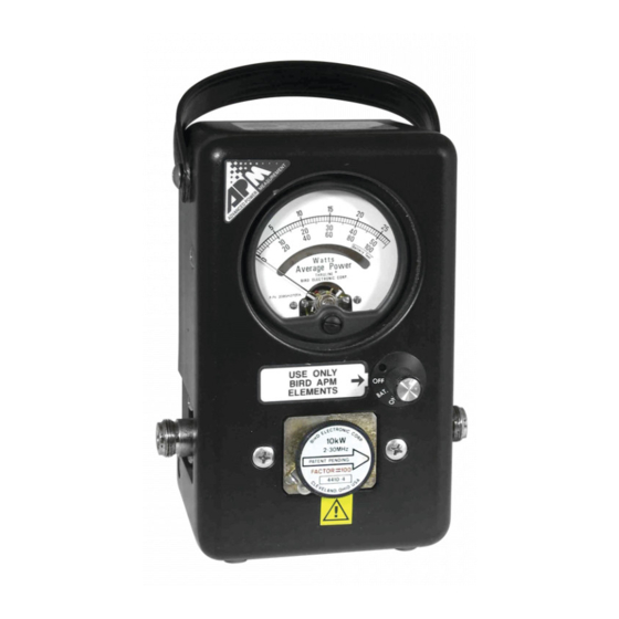
Summary of Contents for BIRD Thruline APM-16
- Page 1 RF Directional Thruline Wattmeter ® Model APM–16 Operation Manual ©Copyright 2016 by Bird Technologies, Inc. Instruction Book Part Number 920-APM16 Rev. E Thruline® and Termaline® are registered trademarks of Bird Electronic Corporation...
-
Page 2: Safety Precautions
Safety Precautions The following are general safety precautions that are not necessarily related to any specific part or procedure, and do not necessarily appear elsewhere in this publication. These precautions must be thoroughly understood and apply to all phases of operation and maintenance. WARNING Keep Away From Live Circuits Operating Personnel must at all times observe general safety precautions. -
Page 3: Safety Symbols
Safety Precautions Safety Symbols WARNING Warning notes call attention to a procedure, which if not correctly performed, could result in personal injury. CAUTION Caution notes call attention to a procedure, which if not correctly performed, could result in damage to the instrument. The caution symbol appears on the equipment indicating there is important information in the instruction manual regarding that particular area... -
Page 4: Caution Statements
RF Directional Thruline® Wattmeter Model APM–16 Caution Statements The following equipment cautions appear in the text and are repeated here for emphasis. CAUTION For low reflection measurements, do not rotate the reflected power element to read forward power. Damage to the element or wattmeter could result. Refer to page 7. -
Page 5: Safety Statements
Safety Precautions Safety Statements USAGE ANY USE OF THIS INSTRUMENT IN A MANNER NOT SPECIFIED BY THE MANUFACTURER MAY IMPAIR THE INSTRUMENT’S SAFETY PROTECTION. EL USO DE ESTE INSTRUMENTO DE MANERA NO ESPECIFICADA POR EL FABRICANTE, PUEDE ANULAR LA PROTECCIÓN DE SEGURIDAD DEL INSTRUMENTO. - Page 6 RF Directional Thruline® Wattmeter Model APM–16 SERVICE SERVICING INSTRUCTIONS ARE FOR USE BY SERVICE - TRAINED PERSONNEL ONLY. TO AVOID DANGEROUS ELECTRIC SHOCK, DO NOT PERFORM ANY SERVICING UNLESS QUALIFIED TO DO SO. SERVICIO LAS INSTRUCCIONES DE SERVICIO SON PARA USO EXCLUSIVO DEL PERSONAL DE SERVICIO CAPACITADO.
- Page 7 Safety Precautions RF VOLTAGE MAY BE PRESENT IN RF ELEMENT SOCKET - KEEP ELEMENT IN SOCKET DURING OPERATION. DE LA TENSION H.F. PEAT ÊTRE PRÉSENTE DANS LA PRISE DE L'ÉLÉMENT H.F. - CONSERVER L'ÉLÉMENT DANS LA PRISE LORS DE L'EMPLOI. HF-SPANNUNG KANN IN DER HF-ELEMENT-BUCHSE ANSTEHEN - ELEMENT WÄHREND DES BETRIEBS EINGESTÖPSELT LASSEN.
-
Page 8: About This Manual
Describes the process for measuring forward and reflected power, includes charts for calculating VSWR, and provides information on load matching. Maintenance — Lists routine maintenance, repair, calibration and troubleshooting procedures for common problems. This section also includes APM-16 specifications, parts information, and Bird Service Center contact information. -
Page 9: Table Of Contents
Table of Contents Safety Precautions ......... i Safety Symbols . - Page 10 RF Directional Thruline® Wattmeter Model APM–16 Contact Adjustment ......... 19 Battery .
-
Page 11: Chapter 1 Introduction
Bumpers on the base and back allow the meter to stand or lie flat. Refer to to identify components. Figure 1 At each end of the line section are Bird Quick-Change RF connectors that may be interchanged with any other Bird “QC” connector. The wattmeter housing does not interfere with connector changes. -
Page 12: Chapter 2 Theory Of Operation
= Watts Reflected = E is the characteristic impedance of a uniform line section. For useful lines it is usually a pure resistance of 50 ohms. The RF circuit of the Bird APM-16 is a length of uniform air line with Z = 50 ohms. -
Page 13: Load Power
Thruline Wattmeter measurements are also independent of position along the transmission line. Like similar diode devices, the Bird APM-16 indicates the carrier component of amplitude modulation, with very little response to side band components added by modulation. - Page 14 = 10 log . VSWR scales and their attendant controls for setting the reference point have been intentionally omitted from the Bird APM-16. Experience using the Thruline Wattmeter for transmitter tune-up, antenna matching, etc. will show that the power ratio measurement is as useful as the standing wave ratio.
- Page 15 Theory of Operation Figure 3 Percent Reflected Power vs. VSWR (1.0 – 8.0)
- Page 16 RF Directional Thruline® Wattmeter Model APM–16 Figure 4 Percent Reflected Power vs. VSWR (1.0 – 1.3...
-
Page 17: Low Reflection
This method should not be used with element ranges differing by more than 10:1. For example, consider an 80 watt transmitter and a Bird APM-16 with 100 and 10 watt elements. Measure W with the 100 W element. Measure W with the 10 W element (make sure the arrow points towards the transmitter). - Page 18 RF Directional Thruline® Wattmeter Model APM–16 Note: Very small attenuations require allowance for normal instrument errors. To correct for this without any calculations, con- nect the wattmeters directly, with no line between them, and adjust their zero settings. 3. Line loss using open circuit calibration: The high directivity of elements can be exploited in line loss measurements, because of the equality of forward and reflected power with the load connector open or short circuited.
-
Page 19: Frequency Response
Theory of Operation Frequency Response Bird Plug-In Elements have a flat frequency response over their specified operating range. A sample set of curves is shown in . Notice that for the Figure 5 low power element, the rolloff outside its frequency band is more pronounced than for the high power elements. -
Page 20: Impedance Mismatch
RF Directional Thruline® Wattmeter Model APM–16 Impedance Mismatch There may be cases where it is necessary to use the Bird APM-16 with a non-50 ohm transmission line. If the reflected power is less than 10% and the frequency is below 200 MHz, the resulting mismatch will not be too serious. At higher frequencies or higher reflected power levels, the load impedance will change when the wattmeter is removed from the circuit. -
Page 21: Chapter 3 Installation
Slide this open and connect the battery. When transporting or storing the Bird APM-16, be sure the power switch is set to OFF. In any other position, there is a slight drain on the battery. -
Page 22: Connecting Rf Power
Figure 6 Securing an element Connecting RF Power Insert the Bird APM-16 in 50 ohm coaxial transmission lines. The RF source can be connected to either side of the wattmeter. Absorption Wattmeter Combining the Thruline Wattmeter with a Bird Termaline Load creates an accurate absorption wattmeter. -
Page 23: Chapter 4 Operating Instructions
Chapter 4 Operating Instructions WARNING RF voltage may be present in element socket. Keep element in socket during operation. Normal Operation 1. Insert the element in the line section socket. 2. To measure forward power, turn the element so that the arrow points towards the load. - Page 24 RF Directional Thruline® Wattmeter Model APM–16 Figure 8 VSWR Conversion Graph (Reflected Power 0.2 – 20.0)\...
- Page 25 Operating Instructions Figure 9 VSWR Conversion Graph (Reflected Power 0.01 – 1.00)
-
Page 26: Load Matching
RF Directional Thruline® Wattmeter Model APM–16 Load Matching When a Bird APM-16 is used to tune a load to a transmitter and a good match is obtained, removing it will not change the match quality. A good 50 ohm load can terminate a 50 ohm transmission line of any length without altering conditions at the transmitter. - Page 27 Operating Instructions Figure 10 Cable Length / Wavelength Matching...
-
Page 28: Chapter 5 Maintenance
Chapter 5 Maintenance The rugged and simple design of the Bird APM-16 means that it requires minimal routine maintenance. Troubleshooting The following table contains troubleshooting information for problems that can occur during normal operation. Find the problem on the table, review possible causes, and perform the corrective action listed. -
Page 29: Maintenance Procedures
Maintenance Maintenance Procedures Cleaning It is important to keep the following surfaces clean: Socket bore DC contacts on the element Teflon insulators If any of the contacts or line connectors are dirty, clean them with a cotton swab dipped in commercial contact cleaner or isopropyl alcohol. -
Page 30: Repair
RF Directional Thruline® Wattmeter Model APM–16 Repair “QC” Connectors The Bird 43 is normally supplied with Quick-Change Female N type connectors. Other Bird “QC” connectors are available (See "Available “QC” Type ). To change a QC connector, remove the Connectors" on page 26 8-32 screw at each corner of the connector and then pull it straight outward. -
Page 31: Calibration
Maintenance Calibration Calibration of the Bird APM-16 will be required after replacing the meter or the instrumentation module, and also when the calibration certification expires. Note: Calibrating the unit, or disturbing the calibration label, within the one-year warranty period will void the warranty. -
Page 32: Calibrating
RF Directional Thruline® Wattmeter Model APM–16 Calibrating 1. Remove any dust plug or element from the APM. 2. Allow the APM and all equipment to stabilize with respect to the workspace environment. Note: The APM and the calibration element may require up to 24 hours for complete stabilization if brought from an extreme stor- age environment. -
Page 33: Storage
If the unit needs to be returned for any reason, request an Return Material Authorization (RMA) through the Bird Technologies website. All instruments returned must be shipped prepaid and to the attention of the RMA number. -
Page 34: Specifications
Shock mounted linear scale with expanded Meter scales of 25, 50 and 100 full scale. Includes 5% overrange. Connectors Bird “QC” N Female normally supplied Standard 9V battery. 200 hours operation, Battery minimum. Operating Position Complies with 89/336/EEC and 92/31/EEC... -
Page 35: Replacement Parts List
Maintenance Replacement Parts List Description Qty. Part Number Housing Assembly 4401A002 Cover Assembly 4401A011 Line Section & 4401A003 Instrumentation Module Carrying Strap (Included in Housing 8580A003 Assembly) Dust Plug, Aluminum 3610-031 Selector Switch Knob 4401A014 Meter, DC 2080A070 Battery 5-1375 RF Connectors See list below... -
Page 36: Available "Qc" Type Connectors
RF Directional Thruline® Wattmeter Model APM–16 Available “QC” Type Connectors Connector Part Number BNC-Female 4240-125 BNC-Male 4240-132 C-Female 4240-100 C-Male 4240-110 HN-Female 4240-268 HN-Male 4240-278 LC-Female 4240-031 LC-Male 4240-025 LT-Female 4240-018 LT-Male 4240-012 Mini UHF-Female 4240-346 N-Female 4240-062 N-Male 4240-063 Open Term. -
Page 37: Limited Warranty
Limited Warranty All products manufactured by Seller are warranted to be free from defects in material and workmanship for a period of one (1) year, unless otherwise specified, from date of shipment and to conform to applicable specifications, drawings, blueprints and/or samples. Seller’s sole obligation under these warranties shall be to issue credit, repair or replace any item or part thereof which is proved to be other than as warranted;...
Need help?
Do you have a question about the Thruline APM-16 and is the answer not in the manual?
Questions and answers