Table of Contents
Advertisement
Quick Links
®
Thruline
RF Power Meter Model 4421
and
®
Thruline
Directional
Rf Power Sensors
4020 Series, 4027A Series,
4027F Series, and 4028 Series
Operation Manual
©Copyright 2016 by Bird Electronic Corporation
Instruction Book Part Number 920-4421 Rev W
®
Thruline
is a Registered Trademark
of Bird Electronic Corporation
Advertisement
Table of Contents

Related Manuals for BIRD Thruline 4020 Series


Summary of Contents for BIRD Thruline 4020 Series
- Page 1 ® Thruline Directional Rf Power Sensors 4020 Series, 4027A Series, 4027F Series, and 4028 Series Operation Manual ©Copyright 2016 by Bird Electronic Corporation Instruction Book Part Number 920-4421 Rev W ® Thruline is a Registered Trademark of Bird Electronic Corporation...
-
Page 2: Safety Precautions
Safety Precautions The following are general safety precautions that are not necessarily related to any specific part or procedure, and do not necessarily appear elsewhere in this publication. These precautions must be thoroughly understood and apply to all phases of operation and maintenance. WARNING Keep Away From Live Circuits Operating Personnel must at all times observe general safety precautions. -
Page 3: Safety Symbols
Safety Precautions Safety Symbols WARNING Warning notes call attention to a procedure which, if not correctly performed, could result in personal injury. CAUTION Caution notes call attention to a procedure which, if not correctly performed, could result in damage to the instrument. The caution symbol appears on the equipment indicating there is important information in the instruction manual regarding that particular area. -
Page 4: Caution Statements
Changing the sensor’s connectors will invalidate calibration data, and may reduce the maximum power rating of the unit. See page 3, 43, 46, 48, and 52. CAUTION The Bird 4421 must be powered off when connecting or disconnecting the power sensor from the power meter. See page 6 and 43. CAUTION Do not use the power sensor with a load VSWR greater then 2:1. -
Page 5: Safety Statements
Safety Precautions Safety Statements USAGE ANY USE OF THIS INSTRUMENT IN A MANNER NOT SPECIFIED BY THE MANUFACTURER MAY IMPAIR THE INSTRUMENT’S SAFETY PROTECTION. EL USO DE ESTE INSTRUMENTO DE MANERA NO ESPECIFICADA POR EL FABRICANTE, PUEDE ANULAR LA PROTECCIÓN DE SEGURIDAD DEL INSTRUMENTO. BENUTZUNG WIRD DAS GERÄT AUF ANDERE WEISE VERWENDET ALS VOM HERSTELLER BESCHRIEBEN, KANN DIE GERÄTESICHERHEIT BEEINTRÄCHTIGT WERDEN. - Page 6 Thruline RF Power Meter, Model 4421 SERVICE SERVICING INSTRUCTIONS ARE FOR USE BY SERVICE-TRAINED PERSONNEL ONLY. TO AVOID DANGEROUS ELECTRIC SHOCK, DO NOT PERFORM ANY SERVICING UNLESS QUALIFIED TO DO SERVICIO LAS INSTRUCCIONES DE SERVICIO SON PARA USO EXCLUSIVO DEL PERSONAL DE SERVICIO CAPACITADO.
- Page 7 Safety Precautions UNITS ARE EQUIPPED WITH RECHAREABLE BATTERIES. THESE ARE TO BE REPLACED BY AUTHORIZED SERVICE PERSONNEL ONLY!!! LAS UNIDADES VIENEN EQUIPADAS CON BATERIAS RECARGABLES. ¡¡¡Y SOLAMENTE EL PERSONAL DE SERVICIO AUTORIZADO PUEDE REEMPLAZARLAS!!! GERÄTE SIND MIT WIEDER AUFLADBAREN BATTERIEN BESTÜCKT. BATTERIEN SIND NUR VON QUALIFIZIERTEM SERICE PERSONAL AUSZUWECHSELN!!! CES DISPOSITIFS SONT ÉQUIPÉS DE BATTERIES RECHARGEABLES.
- Page 8 Thruline RF Power Meter, Model 4421 BE SURE THE 115/230V AC VOLTAGE SELECTOR IS SET TO THE PROPER LINE VOLTAGE, AND THE CORRECT AC LINE FUSE IS INSTALLED BEFORE AC POWER IS APPLIED. S’ASSURER QUE LE SÉLECTEUR DE TENSION 115/230V C.A. EST BIEN RÉGLÉ POUR LA TENSION DU RÉSEAU ET QUE LE FUSIBLE DE LIGNE C.A.
-
Page 9: About This Manual
About This Manual About This Manual This manual covers the Bird 4421 RF Power Meter and the its sensors. This manual covers the operating and maintenance instructions for the following models: Power Meter 4421 4021 4022 4024 4025 4020 Series... -
Page 10: Table Of Contents
Table of Contents Safety Precautions ..............i Safety Symbols . - Page 11 Table of Contents Chapter 5 RS-232 Interface ............24 Description .
-
Page 12: Chapter 1 Introduction
The Bird 4421 RF Power Meter is one component of a complete RF power measurement system. An RF power sensor such as a Bird 4021 is also required. The system can be controlled with the front panel buttons, or remotely through an RS-232 connection or a GPIB-488 connection. - Page 13 Introduction Figure 1 Bird 4421 Meter Outline Drawing 1. Operating Push Buttons 2. LCD 3. ON/OFF Push Button 4. Handle 5. Central Button 6. Fuse Access Door 7. AC Line Module 8. Master ON/OFF Switch 9. GPIB connector 10. GPIB DIP switches 11.
-
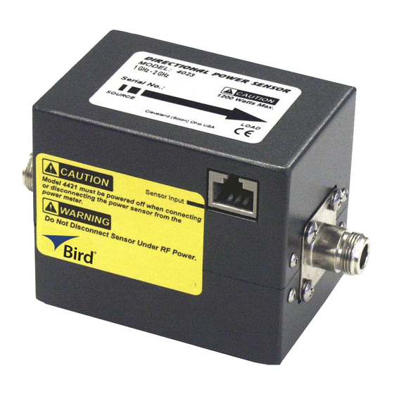
Page 14: Power Sensors
4020 Series Bird 4020 Series Power Sensors are designed for lab or field use and are accurate to within ± 3%(1) of reading. 4027A Series Bird 4027A Series Power Sensors are designed for use in semiconductor processing and calibration applications. -
Page 15: Frequency And Power Ranges
Introduction Figure 3 Power Sensor Outline Drawing 4028B Series only Figure 4 Power Sensor Outline Drawing 4028C Series only Frequency and Power Ranges 4020 Series Model Frequency Range RF Power Range 4021 1.8 – 32 MHz 300 mW – 1 kW 4022 25 –... -
Page 16: 4027A Series
Thruline RF Power Meter, Model 4421 4027A Series Model Frequency Range RF Power Range 4027A250K 250 – 400 kHz 3 W – 10 kW 4027A400K 400 – 550 kHz 3 W – 10 kW 4027A800K 800 – 950 kHz 3 W – 10 kW 4027A2M 1.5 –... -
Page 17: Chapter 2 Installation
Changing the sensor’s connectors will invalidate calibration data, and may reduce the maximum power rating of the unit. CAUTION The Bird 4421 must be powered off when connecting or disconnecting the power sensor from the power meter. 1. Turn OFF the ON/OFF rocker switch on the meter’s rear panel. -
Page 18: Handle Operation
Figure 5 Panel Mounting Dimensions Handle Operation The handle on the Bird 4421 can be set to four different positions (see Figure 6). To adjust the handle, press the center buttons on both sides. Releasing the buttons will lock the handle into position. -
Page 19: 115/230V Ac Input Power
Batteries The Bird 4421 RF Power Meter is completely portable and is powered from internal rechargeable nickel metal hydride batteries. The batteries are shipped in a low charge state. It is, therefore, recommended that you charge the instrument for approximately 28 hours before using it for continuous operation. -
Page 20: Chapter 3 Operating Instructions
Chapter 3 Operating Instructions This chapter describes operator controls and indicators on the Bird 4421 RF Power Meter. For remote operation using a IEEE-488 (GPIB) or RS-232 controller, refer to the instructions in Chapter 4 Chapter 5 respectively. Push Button Functions... -
Page 21: Error Codes
Operating Instructions Error Codes The Bird 4421 displays error codes when the RF power is either below the selected range (underrange) or above the selected range (overrange). Table 1 displays the error codes and Table 2 lists the function limits. -
Page 22: Chapter 4 Ieee-488 Gpib Interface
Failure to detect a service request could result in equipment damage. Description The Bird 4421 IEEE-488 (GPIB) interface has an eight-position DIP switch that sets operational conditions and interface addresses. The bottom line of the display indicates the current bus status. Cable Connector The interface uses a standard IEEE-488 cable connector. -
Page 23: Interface Capabilities
Does not have extended talker capability. Extended Listener Does not have extended listener capability. Indicators The bottom line of the power meter’s display shows indicators describing the status of the Bird 4421 when used with the IEEE interface. These are: REMOTE —... -
Page 24: Talker-Only Mode
Talker-Only Mode The Bird 4421 can be set up for manual operation while automatically sending data to an output device (Talker-Only Mode). To do so, turn DIP switch 1 OFF and cycle the power. TALK will be displayed. - Page 25 IEEE-488 GPIB Interface IDentificatioN (IDN?) Function Product identifies itself Remarks Replies command same as U2 Remote ENable (REN) Function Enables remote operation. Remarks The unit must be addressed to listen after setting REN true. The REMOTE indicator turns on when this command is received. Go To Local (GTL) Function...
- Page 26 Thruline RF Power Meter, Model 4421 Device CLear (DCL) Function Resets the status of all devices to an initialized state. Remarks Does not change the current interface mode. The 4421 returns to the factory default condition listed in Table Table 6 IEEE-488 Default Conditions Default Condition Related Command...
- Page 27 IEEE-488 GPIB Interface Serial Polling Enable/Disable (SPE/SPD) Function Enables or disables the serial polling sequence. CAUTION During remote operation, periodically monitor the bus service request line. Failure to detect a service request could result in equipment damage. Remarks The SPE command puts all devices in serial poll mode waiting to be addressed. The SPD command clears the SRQ bit (bit 6) and ends the polling sequence.
-
Page 28: Device Dependent Commands
Thruline RF Power Meter, Model 4421 Device Dependent Commands The device-dependent commands used by the 4421 Power Meter are listed in Table 8, organized by category. Note: The programming card also has a complete command list. Table 8 IEEE-488 Device Dependent Command Summary Category Command Description... - Page 29 IEEE-488 GPIB Interface Forward Carrier Wave (FC) Forward dBm (FD) Reflected Carrier Wave (RC) Reflected dBm (RD) Function Selects forward or reflected RF power measurement mode. Remarks Measurement results are returned in Watts or dBm. Standing Wave Ratio (SW) Return Loss (RL) Function Selects SWR or return loss match measurement mode.
- Page 30 Thruline RF Power Meter, Model 4421 Range (Rxx) Function Selects a measurement range listed in Table Remarks If the selected range is outside the range of the connected power sensor, the command is ignored. Table 9 Measurement Ranges Command Power Range Turn auto range on Turn auto range off.
- Page 31 “U” indicates underflow; the value sent is “.000”. “O” indicates overflow; the value sent is “199.9”. “N” indicates normal; the value sent is a normal on-scale reading. “4421” indicates the Bird model number. Table 10 Prefix Examples Data String Description NFC.0.123W(CR)(LF) Normal (N) forward carrier wave (FC), prefixes on OFC 199.9W(CR)(LF)
- Page 32 Thruline RF Power Meter, Model 4421 SRQ Mask (Mxx) Function Selectively masks status bits to prevent unwanted service requests. Set xx to the sum of the binary values of the desired SRQ trigger bits. For example, M12 would set the SRQ for both operation complete and underrange (values 8 and 4).
- Page 33 IEEE-488 GPIB Interface Error Status Word (U1) — The format of the error status word and the possible error messages are shown in Figure 10. When an error occurs, an error is also flagged in the status (serial poll) byte, and a SRQ may be generated ("SRQ Mask (Mxx)"...
- Page 34 Thruline RF Power Meter, Model 4421 Self Test (J0) Function Initiates a hardware and software test. Remarks Results are stored in the U1 status word ("Status (Ux)" on page 21). “J0” must be sent each time before reading the result. End Or Identify (Kx) Function Enables or disables the End or Identify (EOI) signal.
-
Page 35: Chapter 5 Rs-232 Interface
Description The Bird 4421 RS-232 interface feature is an integral part of the I/O hub circuit board inside of the mm21. An eight- position DIP switch is used to set operational conditions such as baud rate, parity, and stop bits. The bottom line of the display indicates the current bus status. -
Page 36: Setup
Thruline RF Power Meter, Model 4421 Setup DIP Switch Set the DIP switches according to application needs and the requirements of the controller. Available settings and factory defaults are listed in Figure Note: There are several button styles on DIP switches (slide, rocker, lever). Examine the DIP switch to determine the ON and OFF positions. -
Page 37: Auto Baud
Talker-Only Mode The Bird 4421 can be set up for manual operation while automatically sending data to an output device (Talker-Only Mode). To do so, turn DIP switch 2 OFF and cycle the power. TALK will be displayed. - Page 38 Thruline RF Power Meter, Model 4421 INiTialize (INT) Function Resets the Bird 4421 and returns it to the factory defaults. Remarks If INT is linked with any other command within a string, it must be separated from that command by a space.
-
Page 39: Device Dependent Commands
RS-232 Interface Xmission Flow Control (XO/XF) Function Enables or disables the XON/XOFF flow control. XO enables flow control. XF disables flow control. Remarks When data is being sent from the power meter to the computer and flow control is enabled, data transmission will be suspended when the XOFF character (hexadecimal 13) is sent by the computer. - Page 40 Thruline RF Power Meter, Model 4421 Forward Carrier Wave (FC) Forward dBm (FD) Reflected Carrier Wave (RC) Reflected dBm (RD) Function Selects forward or reflected RF power measurement mode. Remarks Measurement results are returned in Watts or dBm. Standing Wave Ratio (SW) Return Loss (RL)
- Page 41 RS-232 Interface Range (Rxx) Function Selects a measurement range listed in Table Remarks If the selected range is outside the range of the connected power sensor, the command is ignored. Table 17 Measurement Ranges Command Power Range Turn auto range on Turn auto range off.
- Page 42 “U” indicates underflow; the value sent is “.000”. “O” indicates overflow; the value sent is “199.9”. “N” indicates normal; the value sent is a normal on-scale reading. “4421” indicates the Bird model number. Table 18 Prefix Examples Data String Description NFC.0.123W(CR)(LF) Normal (N) forward carrier wave (FC), prefixes on OFC 199.9W(CR)(LF)
- Page 43 RS-232 Interface Status (Ux) Function Reads a status word and returns the information as a string. Set x to: “0” for machine status. “1” for error status. “2” for revision history. Remarks After sending the status command, a status word is sent the next time the unit is addressed to talk.
- Page 44 Thruline RF Power Meter, Model 4421 Revision History Word (U2) — The format of the revision history word is shown in Figure Figure 15 Revision History Word Format Self Test (J0) Function Initiates a hardware and software test. Remarks Results are stored in the U1 status word (see "Status (Ux)"...
-
Page 45: Chapter 6 Maintenance
Do not use harsh or abrasive detergents for cleaning. Clean the Bird 4421 Power Meter and its display with a soft cloth dampened with mild detergent and water only. Clean sensors with a dry cleaning solvent that leaves no residue. -
Page 46: Functional Test
Thruline RF Power Meter, Model 4421 PROBLEM POSSIBLE CAUSE CORRECTION Have the batteries been charged? Recharge the batteries. Is the power meter’s ac power Connect the power cord. cord connected? Is the ON/OFF rocker switch on Set the switch to ON. the rear panel set to OFF? Power meter has no power (Cal Cart only) -
Page 47: Push Button Test
Maintenance Note: The unit tests the display on power up cycling through and activating each segment two times and then activating all segments at once two times. 4. The power meter’s model number and revision date should scroll across the display. If a dash “–” is displayed instead, then the meter is malfunctioning. -
Page 48: Power Meter Repair
Thruline RF Power Meter, Model 4421 11. Press dBm. Note: “dBm” should change to “SWR”. 12. Press FWD. Note: “SWR” should change to “FWD” and “ ” to “.0000 W” (or a very low number). 13. Hold down MAX. Note: “.0000” should change to “1.0000”. 14. - Page 49 Maintenance AC Line Voltage Fuse Rating 115 Vac T630 mA, 5x20 mm Time Lag Fuse 230 Vac T315 mA, 5x20 mm Time Lag Fuse Figure 17 AC Line Fuse...
-
Page 50: Replacing Batteries
Thruline RF Power Meter, Model 4421 Replacing Batteries There are two battery configurations in the 4421 Power Meter. In the larger case models (before 2016), the batteries are horizontally arranged, in units with a smaller case the batteries are vertically arranged in a battery assembly. -
Page 51: Replace Batteries (Newer Models)
Maintenance Figure 18 Batteries Item Description Battery retaining belt Battery tube (batteries inside) Replace Batteries (Newer Models) WARNING Exposed AC line voltage (115 VAC or 230 VAC). Disconnect the power cord from the AC line before replacing the batteries. Failure to comply may result in severe electrical shock or death. - Page 52 Thruline RF Power Meter, Model 4421 Figure 19 Battery Assembly Removal 6. Lift the battery assembly out of the Power Meter. 7. Unfasten the battery retaining belts then remove the battery tubes (Figure 20). Be sure to note the polarity and orientation of the battery tubes before removing them.
-
Page 53: Long Term Storage
Maintenance Long Term Storage Do not store the instrument for long periods of time without recharging the batteries. When the instrument is stored for long periods of time without use, the batteries will loose their charge and also loose the ability to reach full charge when put into service. -
Page 54: Power Sensor (Cal Cart Only)
Never attempt to connect or disconnect RF equipment from the transmission line while RF power is being applied. Leaking RF energy is a potential health hazard. CAUTION The Bird 4421 must be powered off when connecting or disconnecting the power sensor from the power meter. CAUTION Changing the sensor’s connectors will invalidate calibration data, and may reduce the... -
Page 55: Casters (Cal Cart Only)
Remove the vent plugs and replace them with the shipping plugs. Wrap the vent plugs with padding and tape them to the side of the load for protection. Note: With the shipping plugs installed, it is not necessary to empty out the coolant. Repack in the original carton or contact Bird for a transit case. -
Page 56: Specifications, Cal Cart
Insertion loss is specified with female N connectors. Choose connectors appropriate for the frequency and power of operation. Derate RF power by 2.5% for every 305m (1,000 ft.) above 1,520m (5,000 ft.). Table 20 Bird Cal Cart Frequency Range Sensor dependent, 30 MHz max. Power Range Dependent on sensor, sensor connectors, and load Customer specified (See "Available Connectors"... -
Page 57: Specifications, 4421 Rf Power Meter
Maintenance Specifications, 4421 RF Power Meter Table 21 Bird 4421 RF Power Meter Frequency Range Sensor dependent Power Range Sensor dependent VSWR Display 1.0 – 199.9 max Return Loss Display 0 to 40 dB max Display Accuracy ± 1 on least significant digit AC Power 115 / 230 Vac @ 50 / 60 Hz;... -
Page 58: Specifications, Power Sensors
Thruline RF Power Meter, Model 4421 Specifications, Power Sensors Table 22 Specifications Common to all Sensors Impedance, Nominal 50 ohms Max. Allowable Terminating VSWR 2.00:1 Frequency-specific calibration factors stored in nonvolatile memory in each sensor. Calibration Technique Sensor output corrected for frequency and temperature within specified ranges. - Page 59 Maintenance Table 23 Bird 4020 Series RF Power Sensors RF Power Range 4021, 4022 300 mW – 1 kW 4024, 4025 3 W – 10 kW Frequency Range 4021 1.8 – 32 MHz 4022 25 MHz – 1 GHz 4024 1.5 –...
- Page 60 Insertion Loss, Max. 0.05 dB (with female “N” connectors) Directivity, Min. 28 dB † Other calibration frequencies available upon request Table 26 Bird 4028A and 4028B Series RF Power Sensors Frequency Range 4028A250K 250 – 400 kHz 4028A400K 400 – 550 kHz 4028A2M 1.5 –...
-
Page 61: Specifications, Rs-232 Interface
Maintenance Calibration Frequencies, Typical †† (MHz) 4028A250K 0.25, 0.40 4028A400K 0.40 4028A2M 1.8, 2.0, 2.17 4028A3M 2.5, 3.2, 3.5 4028A4M 3.5, 4.0 4028A10M, 4028B10M, 4028C10M 10.0, 13.56, 15.0 4028A25M 25.76, 27.12, 28.48 4028B3M 2.5, 3.2, 3.5, 4.0 Calibration Power, Typical 3.5 kW VSWR, Max. - Page 62 Thruline RF Power Meter, Model 4421 Figure 22 High Frequency Derating 1 Figure 23 High Frequency Derating 2...
-
Page 63: Replacement Parts
Maintenance Replacement Parts Table 29 Replacement Parts Description Part Number Fuse, IEC (5 x 20 mm) Time Lag Type T 115 VAC, T630 mA 5A2257-14 230 VAC, T315 mA 5A2257-11 Cord, AC Power 115 VAC 5-1286 230 VAC Harmonized 5A2416 Plug, 115 VAC 5A2626 Cable, Sensor... -
Page 64: Customer Service
Any maintenance or service procedure beyond the scope of those in this chapter should be referred to a qualified service center. If the unit needs to be returned for any reason, request an Return Material Authorization (RMA) through the Bird Technologies website. All instruments returned must be shipped prepaid and to the attention of the RMA number. -
Page 65: Limited Warranty
4027F, and Series 4028 Thruline Power Sensor Heads for lifetime to original purchaser. This extended warranty is against burnout. For the warranty to apply, the Sensor Head must be used with the correct Bird Electronic Corpora- tion Display Unit, the maximum power rating of the Sensor must not be exceeded, the Sensor RF circuit must be properly terminated and the Sensor not subjected to physical abuse.
Need help?
Do you have a question about the Thruline 4020 Series and is the answer not in the manual?
Questions and answers