Fluke tix640 User Manual
Thermal imager
Hide thumbs
Also See for tix640:
- User manual (99 pages) ,
- Quick start (2 pages) ,
- User manual (99 pages)
Table of Contents
Advertisement
Quick Links
Test Equipment Depot - 800.517.8431 - 99 Washington Street Melrose, MA 02176 - TestEquipmentDepot.com
TiX640, TiX660, TiX1000
Thermal Imager
PN 4583397
September 2014
© 2014 Fluke Corporation. All rights reserved. Specifications are subject to change without notice.
All product names are trademarks of their respective companies.
Advertisement
Table of Contents

Subscribe to Our Youtube Channel
Related Manuals for Fluke tix640


Summary of Contents for Fluke tix640
- Page 1 Test Equipment Depot - 800.517.8431 - 99 Washington Street Melrose, MA 02176 - TestEquipmentDepot.com TiX640, TiX660, TiX1000 Thermal Imager PN 4583397 September 2014 © 2014 Fluke Corporation. All rights reserved. Specifications are subject to change without notice. All product names are trademarks of their respective companies.
- Page 2 LIMITED WARRANTY AND LIMITATION OF LIABILITY This Fluke product will be free from defects in material and workmanship for two years from the date of purchase. This warranty does not cover fuses, disposable batteries, or damage from accident, neglect, misuse, alteration, contamination, or abnormal conditions of operation or handling.
-
Page 3: Table Of Contents
Chapter Title Page Before You Start ......................1-1 Introduction ........................1-3 How to Contact Fluke ..................... 1-4 Safety Information ......................1-4 Optional Accessories ...................... 1-8 Technical Description ..................... 1-8 Functional Principle ....................1-8 Description of the Functional Units ................1-8 Lens ........................ - Page 4 TiX640, TiX660, TiX1000 Users Manual Parts of the Thermal Imager ..................1-15 Quick Guide ........................1-17 Preparation ....................... 1-18 Start .......................... 1-18 Display ........................1-19 Setting the Focus ...................... 1-20 Setting the Temperature Range ................1-20 Saving Images ......................1-23 Saving with "Check"...
- Page 5 Contents (continued) Setting the Temperature Scale ..................2-9 Focus ..........................2-10 ® LaserSharp Auto Focus ................... 2-10 ® Permanent LaserSharp Auto Focus ................. 2-10 EverSharp Multifocal Recording ................2-10 Spot Editor ........................2-11 Saving ..........................2-11 Saving with Check ......................2-12 Quick Saving ........................
- Page 6 TiX640, TiX660, TiX1000 Users Manual Measurement Definitions Submenu ................3-28 Correction Submenu ....................3-32 GPS Submenu ......................3-36 Laser Submenu ......................3-36 Settings Menu ........................ 3-37 Calibration Submenu ....................3-37 Extras Submenu ....................... 3-38 Automatic Submenu ....................3-39 Compensation Submenu ..................3-40 Buttons Submenu .....................
- Page 7 List of Tables Table Title Page 1-1. Symbols ..........................1-7 1-2. Thermography System with 1024 x 768 IR Pixel Resolution ..........1-9 1-3. Thermal Imager Components ....................1-15 1-4. Front View of Thermal Imager ....................1-16 1-5. Control Locations ........................1-17 1-6.
- Page 8 TiX640, TiX660, TiX1000 Users Manual...
- Page 9 List of Figures Figure Title Page 1-1. Lens Cover Laser Warning ....................1-5 1-2. Ethernet Cable and AC Adapter .................... 1-27 1-3. AC Adapter ..........................1-27...
- Page 10 TiX640, TiX660, TiX1000 Users Manual viii...
-
Page 11: Before You Start
Chapter 1 Before You Start Title Page Introduction ......................1-3 How to Contact Fluke ....................1-4 Safety Information ....................1-4 Optional Accessories ....................1-8 Technical Description ....................1-8 Functional Principle ................... 1-8 Description of the Functional Units ..............1-8 Lens ......................1-8 Detector ......................1-10... - Page 12 TiX640, TiX660, TiX1000 Users Manual Unpacking and Control ................... 1-14 Parts of the Thermal Imager ................... 1-15 Quick Guide ......................1-17 Preparation ...................... 1-18 Start ......................... 1-18 Display ......................1-19 Setting the Focus ..................... 1-20 Setting the Temperature Range ..............1-20 Saving Images ....................
-
Page 13: Introduction
Diverse accessories and different software packages for Introduction pre- and post-processing of the recordings turn the The TiX640, TiX660, and TiX1000 Thermal Imagers (the product into a universal thermography system for a broad Product) are state-of-the-art thermography systems for range of applications. -
Page 14: Safety Information
TiX640, TiX660, TiX1000 Users Manual Safety Information A Warning identifies conditions and procedures that are dangerous to the user. A Caution identifies conditions and procedures that can cause damage to the Product or the equipment under test. Warning To prevent eye damage and personal injury: •... - Page 15 Before You Start Safety Information • • The Product is equipped with an LED Do not use the Product around explosive light to illuminate the image. Avoid any gas, vapor, or in damp or wet direct eye contact and do not point the environments.
- Page 16 Do not disassemble the battery. correct to prevent battery leakage. • Do not short the battery terminals • Use only Fluke approved power adapters together. to charge the battery. • Do not disassemble or crush battery cells and battery packs.
-
Page 17: Symbols
Category: With reference to the equipment types in the WEEE Directive Annex I, this product is classed as category 9 “Monitoring and Control Instrumentation” product. Do not dispose of this product as unsorted municipal waste. Go to Fluke's website for recycling information. -
Page 18: Optional Accessories
TiX640, TiX660, TiX1000 Users Manual Optional Accessories Technical Description ac adapter with 14-pin LEMO connector • Functional Principle replacement lenses, macro attachments The Product is a thermography system designed for the • long-wave infrared spectral range (LWIR) of 7.5 µm to protective window for lenses, laser protection filter •... - Page 19 Before You Start Technical Description Table 1-2 is a list the optional lenses that are available: Table 1-2. Thermography System Lenses 1024 x 768 640 x 480 Focal IFOV Model Lens distance Focus (m) FOV (°) IFOV (mrad) FOV (°) (mrad) (mm) FLK-Xlens/Sup-Wide...
-
Page 20: Detector
TiX640, TiX660, TiX1000 Users Manual Image Processing Electronics Detector With the help of an FPGA (Field Programmable Gate The thermal imager is equipped with an uncooled Array) and up to two processors, real-time image microbolometer FPA detector (uncooled Focal Plane... -
Page 21: Optomechanics
Before You Start Technical Description Specific modes of camera operation and presettings can Optomechanics be configured using menus. Chapter 2 contains a detailed With the help of an optomechanic assembly, the following description of how to operate the thermography system, functions are implemented: as well as a detailed description of the menu structure. -
Page 22: Interfaces
USB 2.0 (mini-AB, behind the cover on the backside • with high temperature option: up to 2000 °C (3632 °F) of the camera) TiX640 ........-40 °C to +1200 °C RS232 (LEMO 14-pin) • (-40 °F to +2192 °F) GigE-Vision (LEMO 8-pin) •... - Page 23 A/D conversion ....... 16-bit (8.25 in x 4.9 in x 6.1 in) Power supply TiX640 ......... 206 mm x 125 mm x 139 mm External ........12 V dc to 24 V dc (8.1 in x 4.9 in x 5.5 in) Battery ........
-
Page 24: Unpacking And Control
Meter/laser pointer, GPS LaserSharp® Auto Focus (TiX660, TiX1000 only) • Auto Focus • rechargeable lithium-ion battery NP-QM91D (Sony) • Manual Focus • (2 with TiX660, TiX1000/1 with TiX640) • EverSharp multifocal recording battery charger • SuperResolution • • Dynamic SuperResolution SDHC card •... -
Page 25: Parts Of The Thermal Imager
Before You Start Parts of the Thermal Imager Parts of the Thermal Imager See Table 1-3 and Table 1-4 for a general overview of the thermal imager components. Table 1-3. Thermal Imager Components hvh013.eps Item Description Item Description WLAN/Bluetooth Connection for GigE-Vision, RS232 ... -
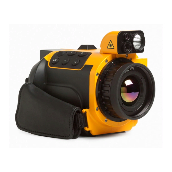
Page 26: Front View Of Thermal Imager
TiX640, TiX660, TiX1000 Users Manual Table 1-4. Front View of Thermal Imager Item Description Color Video Camera Lens Laser Range Finder LED Video Light Color TFT Display hvh014.eps 1-16... -
Page 27: Quick Guide
Before You Start Quick Guide Quick Guide Table 1-5 shows the location of the controls on your thermal imager. In order to achieve professional results, we recommend thoroughly reading the entire manual. Table 1-5. Control Locations Item Description Focus rocker switch with autofocus ... -
Page 28: Preparation
Remove the protective cap from the lens. • thermal imager rechargeable lithium-ion battery or ac adapter with Push . The imager turns on and the Fluke logo • displays during the boot process. At system LEMO connector initialization the power-on LED initially flashes green ®... -
Page 29: Display
Before You Start Quick Guide Display Table 1-6 shows the location of the display elements. Table 1-6. Arrangement of the Image Elements hvh022.eps Item Description Item Description Camera menu Rechargeable battery, SDHC card Temperature unit Status indications ... -
Page 30: Setting The Focus
TiX640, TiX660, TiX1000 Users Manual Initially, you must select a motif with a contrasting scene Setting the Temperature Range (an active electrical device) and point the thermal imager Push the button (shortly). The thermography system towards this scene. will automatically set a temperature scale of the false... - Page 31 Before You Start Quick Guide as well. In this, the respective joystick and button Depending on the selected input variant, the joystick can be used in order to set the temperature level and the functions are displayed to the left of the thermal image. temperature range (Level/Range) or the upper and lower The respective input dialog for numerical input is displayed in the center of the field of view:...
- Page 32 TiX640, TiX660, TiX1000 Users Manual If the options Level/Range and Maximum/Minimum are will then be displayed by on the right side of the set manually, the temperature scale can be adapted image above the color palette. The AUTO mode is...
-
Page 33: Saving Images
Before You Start Quick Guide Saving Images Quick Saving In order to save the thermal image, the button is Immediately push the button completely image is required. The following variants are possible: saved immediately: , the camera control then ... -
Page 34: Menu Functions
TiX640, TiX660, TiX1000 Users Manual Sub-menus can be opened by using the button (Enter) Menu Functions on the respective menu item, for example, push the The thermal imager offers a large number of analysis and button in order to open the sub-menu for automatic functions and can be configured individually for manually setting the temperature range. -
Page 35: Data Transmission To The Computer
Before You Start Data Transmission to the Computer Data Transmission to the Computer Power Supply When using a rechargeable battery, the battery must be ® SmartView software will enable the transmission of data placed on the adapter plate. Push down the rechargeable via the optional GigE Vision (available in 2015). -
Page 36: Lens Replacement
TiX640, TiX660, TiX1000 Users Manual Lens Replacement Operation using the Gigabit Ethernet (GigE) Interface Only replace the lenses in dry and low-dust conditions. IP 54 When the lens is removed, the degree of protection Please proceed as follows in order to connect the thermal of the system is no longer guaranteed! imager to a PC/notebook. -
Page 37: Ethernet Cable And Ac Adapter
Before You Start Start-Up Ethernet Cable and AC Adapter AC Adapter Connection The Ethernet cable is used in order to connect the To operate while permanently connected to a notebook or thermography camera to the 8-pin LEMO socket (left- PC, the power should be supplied using the ac adapter hand side, blue mark). -
Page 38: Breakout Box
TiX640, TiX660, TiX1000 Users Manual Connect the breakout box to the COM interface of Caution the host computer with a commercially available Follow the specified steps on how to cable. establish the required connections. Connect the supplied ac adapter to the breakout box. -
Page 39: Trigger Function
Before You Start Start-Up SyncOut Trigger Function The frame rate of the thermal imager cannot be controlled Triggering uses the Ethernet to affect the 16-bit data from the outside. In order to synchronize other cameras transmission. The TTL/CMOS signal is forwarded to the and processes, and for active thermography applications, thermal imager (right-hand side socket) using the BNC the Framesync signal of the thermal imager can be... - Page 40 TiX640, TiX660, TiX1000 Users Manual 1-30...
-
Page 41: Elements Of The User Interface
Chapter 2 Elements of the User Interface Title Page Introduction ......................2-3 Button Functions ...................... 2-5 Image Elements ....................... 2-7 Setting the Temperature Scale ................. 2-9 Focus ........................2-10 ® LaserSharp Auto Focus ..................2-10 ® Permanent LaserSharp Auto Focus ...............2-10 EverSharp Multifocal Recording ...............2-10 Saving ........................2-11 Saving with Check ....................2-12 Quick Saving ......................2-12... - Page 42 TiX640, TiX660, TiX1000 Users Manual...
-
Page 43: Introduction
Elements of the User Interface Introduction Within the framework of the description of the camera Introduction functions, the letter is attached to the symbol of the The thermal imager has these controls (see Table 2-1): respective function button if a button must be pushed for a longer period of time. -
Page 44: Control Locations
TiX640, TiX660, TiX1000 Users Manual Table 2-1. Control Locations Item Description Focus rocker switch with autofocus Temperature Auto Multifunction 2 Multifunction 1 Save Joystick Power ... -
Page 45: Button Functions
Elements of the User Interface Button Functions Button Functions The functions are assigned (factory defaults) to the function buttons in such a way that functions required frequently can be executed quickly: Table 2-2. Shortcuts Button Type Function Explanation short Auto Mode (Span) Automatic adaptation temperature scale ... - Page 46 TiX640, TiX660, TiX1000 Users Manual The function of the save button when saving images is The Power button is used to turn on the thermal defined in the Saving Format Submenu (see Chapter 3, imager. Initially, the status LED on the left-hand side above the ...
-
Page 47: Image Elements
Elements of the User Interface Image Elements Image Elements The image elements have the following functions: Table 2-3. Image Elements Image Element Location Function Image Central display area Display of the current thermal image, visual light image or of a superimposition of both images, display of saved images Menu Left from screen area... - Page 48 TiX640, TiX660, TiX1000 Users Manual Table 2-2. Image Elements (cont.) Status symbols Lower screen area, right Status indicators for: power supply (ac adapter/status rechargeable battery) • SDHC card • laser distance meter/laser pointer • photo LED • GPS reception Information...
-
Page 49: Setting The Temperature Scale
Elements of the User Interface Setting the Temperature Scale In addition to the current temperature scene in false color Setting the Temperature Scale representation, different image elements are used in At system start (pushing the power button ), the order to show information about the camera status and camera is in Live mode. -
Page 50: Focus
TiX640, TiX660, TiX1000 Users Manual ® Focus LaserSharp Auto Focus To setup: Carefully setting the focus is important to achieve a precise temperature measurement with the thermography Go to Laser menu and select LaserSharp Auto system. Focus. Use the focus rocker switch to: Push the center function of the focus rocker switch. -
Page 51: Spot Editor
Elements of the User Interface Spot Editor Saving Spot Editor Thermography images and photographic pictures are By pushing the button, a temperature measuring point saved to the SC card inserted into the camera. The is created in the center of the image. Pushing the thermal imager supports commercially available SD button with the spot turned on will turn off the measuring and/or SDHC cards up to a capacity of 32GB. -
Page 52: Saving With Check
TiX640, TiX660, TiX1000 Users Manual Saving with Check Quick Saving To check the image to be recorded before saving it, the Using the thermal imager, you can immediately save Live mode should be stopped: images in the Live mode or directly from the motion: •... -
Page 53: Display Menus
Chapter 3 Display Menus Title Page Introduction ......................3-3 Image Submenu ....................... 3-4 Manual Submenu ....................3-5 Mode Submenu ....................3-7 Zoom Submenu ....................3-10 Palette Submenu ....................3-11 Elements Submenu ..................3-14 Isotherms Submenu ..................3-15 Filter Mode Submenu ..................3-17 Format (Subwindowing) Submenu ..............3-17 File Menu ........................3-17 Directory Structure ...................3-18 Load Submenu ....................3-18... - Page 54 TiX640, TiX660, TiX1000 Users Manual Measure Menu ......................3-27 Spot Temperature Submenu ................3-27 Measurement Definitions Submenu ..............3-28 Correction Submenu ..................3-32 GPS Submenu ....................3-36 Laser Submenu ....................3-36 Settings Menu ......................3-37 Calibration Submenu ..................3-37 Extras Submenu ....................3-38 Automatic Submenu ..................
-
Page 55: Introduction
Display Menus Introduction Introduction The menu can be navigated using the joystick settings are accepted using the joystick center button The main menu is designed to select and set the different (Enter). The four main menus are located on the upper functions of the thermal imager. -
Page 56: Image Submenu
TiX640, TiX660, TiX1000 Users Manual Image Submenu Within the menus, the joystick is used to navigate to the top and/or to be bottom ↓. The main menus can be ↑ The Image menu constitutes a summary of the settings switched using the buttons and →. -
Page 57: Manual Submenu
Display Menus Image Submenu Manual Submenu Different modes can be selected for manually setting the The option of manually setting the temperature scale is a temperature range in the "Manual" menu item: central function of each thermography camera. Therefore, this function is arranged in a quickly accessible menu in Level/Range •... - Page 58 TiX640, TiX660, TiX1000 Users Manual functions are displayed to the left of the thermal image Depending on the selected input variant, the joystick instead of the menu after opening the function. The can be used to set the temperature level and the...
-
Page 59: Mode Submenu
Display Menus Image Submenu Along with the option of manually setting the temperature Mode Submenu scale, the temperature scale can be set once by pushing In Live mode, the thermal imager displays thermal images the joystick Enter button shortly, or permanently active, by (infrared images), video images (Digital images), or the pushing the joystick Enter button longer. - Page 60 TiX640, TiX660, TiX1000 Users Manual Digital image mode Infrared Image Mode In the Digital image mode, the camera-internal digital In the Infrared Image mode, the thermal image is shown photo channel is operated in video mode and displayed in false color representation. Depending on the with a geometric resolution of (1024 x 720) pixels.
- Page 61 Display Menus Image Submenu Color Alarm ® ® IR Fusion with Autoblend Technology (Picture-in-Picture) In the Color Alarm mode, a (partial) temperature interval is defined within the set temperature range. Partial areas, In the Picture-in-Picture mode, a part of the infrared the temperatures of which are within this interval, are image is superimposed over the digital image, regardless displayed as an infrared image in false color...
-
Page 62: Zoom Submenu
TiX640, TiX660, TiX1000 Users Manual High Alarm, Low Alarm Zoom Submenu Just as in Interval, a (partial) temperature interval is Depending on the equipment, the thermal imager defined in the High Alarm and Low Alarm modes, not only supports digital magnification of the infrared image and the upper and/or lower limits are defined for the partial the Digital image (visible light image) up to 32-fold. -
Page 63: Palette Submenu
Display Menus Image Submenu Palette Submenu The current allocation of the individual colors/shades of gray of the false color representation to the corresponding temperatures is performed by using the palette shown on the right-hand side margin of the screen. In this, the maximum value of the image area above and its minimum value below the palette serve the purpose of orientation for the temperature level. -
Page 64: Palettes
TiX640, TiX660, TiX1000 Users Manual Table 3-1. Palettes Palette containing 256 colors Grayscale/Rainbow palette with Grayscale palette (left) and (left) and 16 colors (right) temperature-linear (left) and Ultra inverted representation (right) Contrast representation 3-12... - Page 65 Display Menus Image Submenu The "Inverse" function can be used to invert the current On the left-hand side, the palette with temperature-linear palette. For example, if the grayscale palette is set, the representation is shown. On the right-hand side, the low temperatures are indicated in darker colors when palette with logarithmic representation of the temperature compared to the higher temperatures by default.
-
Page 66: Elements Submenu
TiX640, TiX660, TiX1000 Users Manual Elements Submenu The "Elements" menu item can be used to individually adapt the user interface by selecting the individual image elements. The menu comprises the two submenus "Elements" and "Hide". The "Elements" submenu can be used to open the "Image elements" dialog to individually select the image elements. -
Page 67: Isotherms Submenu
Display Menus Image Submenu the same temperature (in a defined temperature interval) Isotherms Submenu with the same representation color and/or shade of gray. In the "Image" menu using the "Isotherms" menu item, With the help of the isotherms editor, it is possible to the isotherms editor can be started and/or settings for create isotherms for differently sized temperature already created isotherms can be made, or all isotherms... - Page 68 TiX640, TiX660, TiX1000 Users Manual Along with the definition of Intervals for isotherms, dialog. At this point, changing the color of the isotherm is identifying temperatures over or under a certain limit is also possible. The 15 "special colors" designed for the possible.
-
Page 69: Filter Mode Submenu
Note This feature is an option. Fluke recommends hvh157.jpg The submenu can be used to select from the four filter that you order the feature at the time of stages: "Off", "Weak", "Medium", and "Strong". -
Page 70: File Menu
TiX640, TiX660, TiX1000 Users Manual 100 = 67,600 files will have been saved to 676 File Menu directories. Those thermal imager functions that can be used to load IR images and photos, to make settings for contents and Please note that a new sub-directory is created after... - Page 71 Display Menus File Menu directory lists and file lists, use the joystick Enter button. A directory can be opened using the joystick Enter button or navigating to the right. The file list of a sub-directory can be closed by navigating to the left. A file, in turn, is selected by using the joystick Enter button.
- Page 72 TiX640, TiX660, TiX1000 Users Manual The button can be used to highlight files and The file selected from the file list (highlighted blue) is directories. The button can be used to delete files and displayed (large) by using the joystick Enter button. When directories.
-
Page 73: Save Submenu
Display Menus File Menu The "Load Gallery" submenu function can be used to The "Saving format" menu item can be used to set the quickly find files from preview images. data and formats to be saved (see Saving Format Submenu on page 3-25). After the function is started, the directories are shown as index cards, the contents of which can be opened and Real-time saving... - Page 74 TiX640, TiX660, TiX1000 Users Manual Real-time saving is started and terminated (immediately) Video saving by pushing the joystick Enter button in the "Real time" If the saved data of a serial measurement does not submenu. The following displays are shown with the real-...
- Page 75 Display Menus File Menu procedure begins. Furthermore, possibly required To start auto capture, the start time (date, time) and the measurement definitions (measuring points or areas) saving interval and the number of IR images to be saved should be defined before starting the measurement. must be defined initially.
-
Page 76: Ir Photonotes Submenu
TiX640, TiX660, TiX1000 Users Manual There is a keyboard for entering alphanumeric characters, whereby this keyboard is shown by pushing the joystick Enter button in the text annotation line. The keyboard can simply be navigated with the joystick Capital and lower-case letters are switched similarly to a computer keyboard. -
Page 77: Format Sd Submenu
Display Menus File Menu Format SD Submenu Saving Format Submenu If all data saved to the SDHC card is to be deleted, this Using the "Saving format" menu item, data to be saved in can be done by formatting the card. The corresponding addition to the thermal image and its format can be function must be started in the "Format SD"... -
Page 78: Setting Selections
TiX640, TiX660, TiX1000 Users Manual Table 3-2 shows the selectable settings. Table 3-2. Setting Selections Setting Selection Format Digital image Saving the visual image synchronously with .is3−thermal image and photo in one file the thermal image .jpg−photo in separate file 1,024 x 720... -
Page 79: Measure Menu
Display Menus Measure Menu Measure Menu The "Measure" menu summarizes all temperature measurement functions. In order that measured values are displayed, the corresponding setting in the "Image elements" menu must be activated (see Elements Submenu on page 3-14). hvh183.jpg Spot Temperature Submenu It is possible to display the (global) temperature maximum and/or temperature minimum within the thermal image by selecting the options "Maximum"... -
Page 80: Measurement Definitions Submenu
TiX640, TiX660, TiX1000 Users Manual In order to create a new AOI, you must initially open the Measurement Definitions Submenu "Editor" submenu and select the required format of the The "Measurement definitions" menu item can be used to measuring object at "New". - Page 81 Display Menus Measure Menu Line L The position of the measuring line can be defined by moving one of the terminal points or by synchronously moving both terminal points simultaneously. The respective "active" point and/or both points are also marked in red. If the button is pressed in the editor, the settings dialog for displaying the measured values is shown.
- Page 82 TiX640, TiX660, TiX1000 Users Manual Rectangle R Polygon PG A rectangle selected in the "Editor" submenu in the "New" The thermal imager supports polygon planes with a menu item is initially displayed as a square in the center maximum of 11 points, the position of which can be of the image.
- Page 83 Display Menus Measure Menu hvh202.jpg hvh203.jpg hvh204.jpg hvh205.jp hvh206.jp hvh207.jpg 3-31...
-
Page 84: Correction Submenu
TiX640, TiX660, TiX1000 Users Manual Polyline PL Correction Submenu In analogy to the polygon (plane), a line can also be The "Correction" menu item can be used to enter the created with a maximum of 11 support points: correction parameters emissivity and ambient... - Page 85 Display Menus Measure Menu The parameters emissivity and ambient temperature, as exact knowledge of the real properties of the measuring well as path temperature, relative humidity, transmission, object, as well as of the ambient conditions and the and distance allow for precise temperature measurement. measurement setup is required.
- Page 86 TiX640, TiX660, TiX1000 Users Manual Note The thermal imager works with a wavelength range of 7.5 to 14 µm. The influence of the atmosphere on the measurement result can be neglected during the majority of the measurements in this range – therefore, the transmission degree is set to 1.00 at the factory.
- Page 87 Display Menus Measure Menu If the actual (lower) emissivity of the measuring object is and can be determined easily. If the "Automatic" option is to be taken into consideration, it is absolutely necessary selected, the distance calculated from the process of to also determine the ambient temperature ("reflected adjusting the focus is displayed after each manual or temperature"), which must also be entered as a...
-
Page 88: Gps Submenu
When this function is activated, the yellow laser symbol When switching off the GPS receiver, the first information will be displayed in the tool bar below the Fluke logo line is hidden automatically. simultaneously with an acoustic signal (2x beep). The laser pointer, integrated depending on the equipment, is activated analogously. -
Page 89: Settings Menu
Display Menus Settings Menu Calibration Submenu Warning The thermal imager is calibrated to measure To prevent eye damage and personal injury: temperatures in the range of (-40…1,200) °C. Depending on the equipment, the total measuring range and the • Do not look into the laser. -
Page 90: Extras Submenu
TiX640, TiX660, TiX1000 Users Manual Caution Extras Submenu The thermal imager is equipped with a highly sensitive uncooled microbolometer detector. The object radiations occurring in thermographic practice do not induce any changes to the detector. However, overloads exceeding a black body radiation of 1,000°C in the measuring ranges 1 and 2, as well as 2,000°C in measuring range 3 may result in... -
Page 91: Automatic Submenu
Display Menus Settings Menu pixel allocation by half a pixel width Automatic Submenu in each case. To use the SuperResolution function, the thermography system must be positioned firmly (tripod) and this function is only suitable for measuring objects with a constant temperature. -
Page 92: Compensation Submenu
TiX640, TiX660, TiX1000 Users Manual button in the setting menus Compensation Submenu Level/Range and Max/Min longer (see In order to implement the specified measurement Manual Submenu on page 3-5). accuracy, the thermal imager performs an internal compensation (factory setting). In this, the optical channel... -
Page 93: Buttons Submenu
Display Menus Settings Menu In the Shutter Interval mode, the interval for an Buttons Submenu automatic compensation can be set. For this, the time The thermal imager can be adapted flexibly to different after which an automatic compensation is to be requirements by individually assigning functions to the performed must be entered in seconds. -
Page 94: Button Functions
TiX640, TiX660, TiX1000 Users Manual Table 3-3 contains a summary of the different functions selectable for the different buttons. To identify the button function as set at the factory, the button symbols are assigned accordingly in the function column. Table 3-3. Button Functions... - Page 95 Display Menus Settings Menu Table 3-3. Button Functions (cont.) Lang Max/Min menu long For manually setting Maximum/Minimum Zoom menu For setting the zoom Isotherms menu For setting the isotherms Infrared/Digital image Switch-over image mode infrared image – Digital image Isotherms on/off Show/hide isotherms Minimum on/off...
-
Page 96: Digital Alarm Output Submenu
TiX640, TiX660, TiX1000 Users Manual The functions can be set in the corresponding input field Digital Alarm Output Submenu for the respective button: The "Digital Alarm Output" menu item can be used to define conditions, the fulfillment of which will trigger the camera to perform actions. -
Page 97: Configuration Submenu
Display Menus Settings Menu Two temperature thresholds can be defined referring to Configuration Submenu the average value ("Average"), the maximum temperature You can save your individual device settings as device value ("Upper limit"), or the minimum temperature value configuration in the thermal imager. This way, you can ("Lower limit") of all defined measuring objects. - Page 98 TiX640, TiX660, TiX1000 Users Manual hvh241.jpg hvh242.jpg hvh244.jpg hvh243.jpg 3-46...
-
Page 99: System Menu
Display Menus System Menu As an alternative to a configuration name generated System Menu automatically consisting of a date and a time, e.g. The "System" menu item contains the settings and cfg_20120622_1530, a name consisting of a maximum of information about the basic functions of the thermal 20 characters can be edited to save the configuration. -
Page 100: Display Submenu
TiX640, TiX660, TiX1000 Users Manual The brightness values of display and viewfinder can be Display Submenu set independently using the levels "Bright", "Medium", The "Display" submenu can be used to select the display and "Dimmed". When the ambient lighting conditions are settings for the thermal imager. -
Page 101: Regional Submenu
Display Menus System Menu Regional Submenu Date and Time Submenu The "Regional" submenu can be used to set the Setting the date and the time corresponds to the language, the date format, the date separator, and the procedure usual for PCs: we recommend entering the time format. -
Page 102: Menu Layout Submenu
TiX640, TiX660, TiX1000 Users Manual However, when navigating to the corresponding menu Menu Layout Submenu item, this menu item is displayed completely even when it The "Menu layout" submenu is used to make the settings exceeds the menu width. for the graphical user interface. The selection options for the font size comprise the 3 levels "Large", "Normal", and... -
Page 103: Menu Control Submenu
Display Menus System Menu Menu Control Submenu The way the navigation in the camera menu is controlled can also be adapted to individual requirements. For quick navigation, the experienced user can set submenus to drop down automatically when a menu item is selected. This way, pushing the Enter button on the corresponding menu item, otherwise necessary, is no longer required. -
Page 104: Info Submenu
TiX640, TiX660, TiX1000 Users Manual Info Submenu The "Info" submenu contains the most important system information for hardware (camera) and system software (system). The SD card page can be used to show the already occupied and/or still available memory space of the SC card inserted into the device. -
Page 105: Maintenance
Chapter 4 Maintenance Title Page Introduction ......................4-3 How to Clean ......................4-3 Calibration ........................ 4-3 Environmental ......................4-3 Service ........................4-4 Battery ........................4-4... - Page 106 TiX640, TiX660, TiX1000 Users Manual...
-
Page 107: Introduction
Interventions of any kind into the In this case, see How to Contact Fluke for more inside of the thermography camera are information. -
Page 108: Service
If correct to prevent battery leakage. exposure to chemicals occurs, clean with water and get medical aid. • Use only Fluke approved power adapters to charge the battery. • Do not disassemble the battery. •...
Need help?
Do you have a question about the tix640 and is the answer not in the manual?
Questions and answers