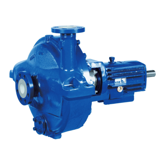
KSB RPH Installation & Operating Manual
Process pump
Hide thumbs
Also See for RPH:
- Installation & operating manual (80 pages) ,
- Supplementary operating manual (8 pages)
Table of Contents
Advertisement
Quick Links
Advertisement
Table of Contents

Related Manuals for KSB RPH


Summary of Contents for KSB RPH
- Page 1 Process Pump Installation/Operating Manual...
-
Page 2: Related Documents
All rights reserved. The contents provided herein must neither be distributed, copied, reproduced, edited or processed for any other purpose, nor otherwise transmitted, published or made available to a third party without the manufacturer's express written consent. Subject to technical modification without prior notice. © KSB Aktiengesellschaft, Frankenthal 11.10.2013... -
Page 3: Table Of Contents
Contents Contents Glossary ....................5 General ....................6 Principles ......................6 Installation of partly completed machinery ............ 6 Target group ..................... 6 Other applicable documents ................6 Symbols ......................6 Safety .....................8 Key to safety symbols/markings ............... 8 General ......................8 Intended use .....................8 Personnel qualification and training ............... - Page 4 Contents Enclosure/insulation ..................24 Checking the coupling alignment ..............25 Aligning the pump and motor ..............26 Electrical connection ..................27 Checking the direction of rotation ..............27 Commissioning/Start-up/Shutdown ...........29 Commissioning/start-up ................. 29 Operating limits ....................36 Shutdown/storage/preservation ..............38 Returning to service ..................38 Servicing/Maintenance ...............40 Safety regulations ...................
-
Page 5: Glossary
Glossary Glossary Back pull-out design Hydraulic system The complete back pull-out unit can be pulled The part of the pump in which the kinetic out without having to remove the pump casing energy is converted into pressure energy from the piping. Pool of pumps Back pull-out unit Pumps which are purchased and stored... -
Page 6: General
(set) and serve as identification for all further business processes. In the event of damage, immediately contact your nearest KSB service centre to maintain the right to claim under warranty. Noise characteristics (⇨ Section 4.6 Page 19) 1.2 Installation of partly completed machinery... - Page 7 1 General Symbol Description Step-by-step instructions Note Recommendations and important information on how to handle the product 7 of 76...
-
Page 8: Safety
2 Safety 2 Safety All the information contained in this section refers to hazardous situations. DANGER 2.1 Key to safety symbols/markings Table 3: Definition of safety symbols/markings Symbol Description DANGER DANGER This signal word indicates a high-risk hazard which, if not avoided, will result in death or serious injury. -
Page 9: Personnel Qualification And Training
2 Safety ▪ Never operate the pump without the fluid handled. ▪ Observe the minimum flow rates indicated in the data sheet or product literature (to prevent overheating, bearing damage, etc). ▪ Observe the maximum flow rates indicated in the data sheet or product literature (to prevent overheating, mechanical seal damage, cavitation damage, bearing damage, etc). -
Page 10: Safety Information For The Operator/User
2 Safety 2.7 Safety information for the operator/user ▪ The operator shall fit contact guards for hot, cold and moving parts and check that the guards function properly. ▪ Do not remove any contact guards during operation. ▪ Provide the personnel with protective equipment and make sure it is used. ▪... - Page 11 If the pump is to be operated at a higher temperature, if there is no data sheet or if the pump is part of a pool of pumps, contact KSB for the maximum permissible operating temperature. 2.10.3...
- Page 12 2 Safety Contact KSB for further information on monitoring equipment. 2.10.4 Operating limits The minimum flows indicated in (⇨ Section 6.2.3.1 Page 37) refer to water and water- like fluids handled. Longer operating periods with these fluids and at the flow rates indicated will not cause an additional increase in the temperatures at the pump surface.
-
Page 13: Transport/Temporary Storage/Disposal
On transfer of goods, check each packaging unit for damage. In the event of in-transit damage, assess the exact damage, document it and notify KSB or the supplying dealer (as applicable) and the insurer about the damage in writing immediately. -
Page 14: Storage/Preservation
3 Transport/Temporary Storage/Disposal max. 90 ° Fig. 3: Transporting the complete pump set max. 90 ° Fig. 4: Transporting the pump on the baseplate 3.3 Storage/preservation If commissioning is to take place some time after delivery, we recommend that the following measures be taken for pump (set) storage. -
Page 15: Disposal
Always indicate any safety and decontamination measures taken. (⇨ Section 11 Page 72) NOTE If required, a blank certificate of decontamination can be downloaded from the KSB web site at: www.ksb.com/certificate_of_decontamination 3.5 Disposal WARNING Fluids, consumables and supplies which are hot or pose a health hazard Hazard to persons and the environment! ▷... -
Page 16: Description Of The Pump (Set)
▪ Process pump to API 610 Pump for handling the large variety of crude oil products in refineries as well as in the chemical and petrochemical industry. 4.2 Designation Example: RPH-H-I S1 80-280B Table 5: Key to the designation Code Description... - Page 17 4 Description of the Pump (Set) ▪ Single-stage ▪ Meets technical requirements to API 610, 11th edition / ISO 13709 Pump casing ▪ Volute casing with integrally cast pump feet ▪ Centreline pump feet ▪ Single or double volute, depending on the pump size ▪...
-
Page 18: Configuration And Function
4 Description of the Pump (Set) Bearings used Table 7: Bearing design KSB designation FAG designation SKF designation B.MUA B-MP-UA BECBM Table 8: Standard bearing assembly Bearing bracket Rolling element bearings Pump end Motor end NU211C3 2 x 7309B-MUA NU213C3... -
Page 19: Noise Characteristics
4 Description of the Pump (Set) Function The fluid enters the pump axially via the suction nozzle (6) and is accelerated outward by the rotating impeller (7). In the flow passage of the pump casing the kinetic energy of the fluid is converted into pressure energy. The fluid is pumped to the discharge nozzle (2), where it leaves the pump. -
Page 20: Installation At Site
5 Installation at Site 5 Installation at Site 5.1 Safety regulations DANGER Improper installation in potentially explosive atmospheres Explosion hazard! Damage to the pump set! ▷ Comply with the applicable local explosion protection regulations. ▷ Observe the information in the data sheet and on the name plates of pump and motor. -
Page 21: Piping
5 Installation at Site ✓ The foundation has been prepared in accordance with the dimensions given in the outline drawing/general arrangement drawing. Position the pump set on the foundation and level it with the help of a spirit level placed on the shaft and discharge nozzle. Permissible deviation 0.2 mm/m. - Page 22 5 Installation at Site NOTE It is recommended to install check and shut-off elements in the system, depending on the type of plant and pump. However, such elements must not obstruct proper drainage or hinder disassembly of the pump. ✓ The suction lift line has been laid with a rising slope, the suction head line with a downward slope towards the pump.
- Page 23 5 Installation at Site CAUTION Aggressive flushing and pickling agents Damage to the pump! ▷ Match the cleaning operation mode and duration for flushing and pickling service to the casing and seal materials used. 5.4.2 Permissible forces and moments at the pump nozzles Fig.
-
Page 24: Enclosure/Insulation
5 Installation at Site Suction nozzle Discharge nozzle Forces Moments Forces Moments [Nm] [Nm] 150-630 9780 7560 6220 13840 7060 3520 5160 9420 4980 4100 6220 8960 4600 2360 3520 6260 200-280 13340 10680 8900 19260 10040 4880 7600 13500 7560 6220 9780... -
Page 25: Checking The Coupling Alignment
5 Installation at Site WARNING The volute casing and casing/discharge cover take on the same temperature as the fluid handled Risk of burns! ▷ Insulate the volute casing. ▷ Fit protective equipment. CAUTION Heat build-up in the bearing bracket Damage to the bearing! ▷... -
Page 26: Aligning The Pump And Motor
Risk of injury by rotating shafts! ▷ Always operate the pump set with a coupling guard. If the customer specifically requests not to include a coupling guard in KSB's delivery, then the operator must supply one! ▷ Observe all relevant regulations for selecting a coupling guard. -
Page 27: Electrical Connection
5 Installation at Site 5.8 Electrical connection DANGER Incorrect electrical installation Explosion hazard! ▷ For electrical installation, also observe the requirements of IEC 60079-14. ▷ Always connect explosion-proof motors via a motor protection switch. DANGER Work on the pump set by unqualified personnel Danger of death from electric shock! ▷... - Page 28 5 Installation at Site WARNING Hands inside the pump casing Risk of injuries, damage to the pump! ▷ Always disconnect the pump set from the power supply and secure it against unintentional start-up before inserting your hands or other objects into the pump.
-
Page 29: Commissioning/Start-Up/Shutdown
6 Commissioning/Start-up/Shutdown 6 Commissioning/Start-up/Shutdown 6.1 Commissioning/start-up 6.1.1 Prerequisites for commissioning/start-up Before commissioning/starting up the pump set, make sure that the following conditions are met: ▪ The pump set has been properly connected to the electric power supply and is equipped with all protection devices. ▪... - Page 30 6 Commissioning/Start-up/Shutdown Fig. 11: Bearing bracket with constant level oiler Constant level oiler Vent plug Connection elbow of the constant Screw plug level oiler Bearing bracket Oil level sight glass Remove the protective cage. Unscrew the vent plug (2). Hinge down the reservoir of the constant level oiler (1) from the bearing bracket (5) and hold it in this position.
- Page 31 6 Commissioning/Start-up/Shutdown Connecting the oil mist lubrication system (for oil mist lubrication only) Bearings with oil mist lubrication Fig. 12: Oil mist lubrication ✓ Always observe the instructions of the lubricating system manufacturer (especially on dosing and oil quantity). Remove plugs 916.N3. Connect the lines of the oil mist lubrication system.
- Page 32 6 Commissioning/Start-up/Shutdown DANGER Risk of potentially explosive atmosphere inside the pump Explosion hazard! ▷ The pump internals in contact with the fluid to be handled, including the seal chamber and auxiliary systems must be filled with the fluid to be handled at all times.
- Page 33 6 Commissioning/Start-up/Shutdown ▪ Maximum permissible cooling liquid test pressure: 15 bar ▪ Observe the specified cooling liquid quantity. 6.1.8 Cooling of the shaft seal CAUTION Vaporisation pressure of fluid handled higher than atmospheric pressure Damage to the shaft seal/pump! ▷ Cool the shaft seal. ▷...
- Page 34 6 Commissioning/Start-up/Shutdown CAUTION Time for warming up the pump too short Damage to the pump! ▷ Check that the pump is sufficiently warmed up throughout. The casing cover can be heated with hot water or steam. Observe the following data for the heating medium: ▪...
- Page 35 6 Commissioning/Start-up/Shutdown CAUTION Abnormal noises, vibrations, temperatures or leakage Damage to the pump! ▷ Switch off the pump (set) immediately. ▷ Eliminate the causes before returning the pump set to service. ✓ The system piping has been cleaned. ✓ Pump, suction line and inlet tank, if any, have been vented and primed with the fluid to be pumped.
-
Page 36: Operating Limits
6 Commissioning/Start-up/Shutdown NOTE If shut-off is not possible, the pump will run in reverse direction. The reverse runaway speed must be lower than the rated speed. For prolonged shutdown periods: Close the shut-off element in the suction line. Close the auxiliary connections. If the fluid to be handled is fed in under vacuum, also supply the shaft seal with barrier fluid during standstill. - Page 37 6 Commissioning/Start-up/Shutdown 6.2.2 Frequency of starts DANGER Excessive surface temperature of the motor Explosion hazard! Damage to the motor! ▷ In case of explosion-proof motors, observe the frequency of starts specified in the manufacturer's product literature. The frequency of starts is usually determined by the maximum temperature increase of the motor.
-
Page 38: Shutdown/Storage/Preservation
6 Commissioning/Start-up/Shutdown Symbol Description Unit Pump discharge head Fluid temperature °C Temperature at the casing surface °C Pump efficiency at duty point Temperature difference 6.2.3.2 Density of the fluid handled The pump input power changes in proportion to the density of the fluid handled. CAUTION Impermissibly high density of the fluid handled Motor overload! - Page 39 6 Commissioning/Start-up/Shutdown In addition, carry out all servicing/maintenance operations before returning the pump (set) to service. (⇨ Section 7 Page 40) WARNING Failure to re-install or re-activate protective devices Risk of personal injury from moving parts or escaping fluid! ▷ As soon as the work is complete, re-install and/or re-activate any safety-relevant and protective devices.
-
Page 40: Servicing/Maintenance
NOTE All maintenance, service and installation work can be carried out by KSB Service or authorised workshops. Find your contact in the attached "Addresses" booklet or on the Internet at "www.ksb.com/contact". -
Page 41: Maintenance/Inspection
7 Servicing/Maintenance 7.2 Maintenance/inspection 7.2.1 Supervision of operation DANGER Excessive temperatures as a result of bearings running hot or defective bearing seals Explosion hazard! Fire hazard! Damage to the pump set! Risk of burns! ▷ Regularly check the lubricant level. ▷... - Page 42 7 Servicing/Maintenance ▪ Check the rolling element bearings for running noises. Vibrations, noise and an increase in current input occurring during unchanged operating conditions indicate wear. ▪ Monitor the correct functioning of any auxiliary connections. ▪ Cooling system Take the pump out of service at least once a year to thoroughly clean the cooling system.
- Page 43 7 Servicing/Maintenance Table 17: Clearances between impeller and casing and/or between impeller and casing cover Size Suction-side casing wear ring Discharge-side casing wear ring Inner nominal Clearance Minimum Inner nominal Clearance Minimum diameter (standard) clearance to diameter clearance to (standard) (rounded) API 610 (rounded)
- Page 44 7 Servicing/Maintenance Size Suction-side casing wear ring Discharge-side casing wear ring Inner nominal Clearance Minimum Inner nominal Clearance Minimum diameter (standard) clearance to diameter clearance to (standard) (rounded) API 610 (rounded) API 610 [mm] [mm] [mm] [mm] [mm] [mm] 400-506 0,85 0,73 0,85...
- Page 45 Undo the screw plug (2) at the bearing bracket (3) and drain the oil. Once the bearing bracket (3) has been drained, re-insert and re-tighten the screw plug (2). Re-fill with oil. For ambient temperatures below -10 °C use a different suitable type of lubricating oil. Contact KSB. 45 of 76...
-
Page 46: Drainage/Cleaning
7 Servicing/Maintenance 7.3 Drainage/cleaning WARNING Fluids, consumables and supplies which are hot or pose a health hazard Hazard to persons and the environment! ▷ Collect and properly dispose of flushing fluid and any residues of the fluid handled. ▷ Wear safety clothing and a protective mask, if required. ▷... - Page 47 7 Servicing/Maintenance 7.4.2 Preparing the pump set Interrupt the power supply and secure the pump against unintentional start-up. Disconnect and remove all auxiliary pipework. Remove the coupling guard. Remove the coupling spacer, if any. Drain the oil fill of oil-lubricated bearings. 7.4.3 Removing the motor NOTE...
- Page 48 7 Servicing/Maintenance 7.4.5.2 Loosening the impeller — for bearing brackets B06 and B07 ✓ The notes and steps stated in (⇨ Section 7.4.1 Page 46) to (⇨ Section 7.4.4 Page 47) have been observed/carried out. ✓ The back pull-out unit has been placed in a clean and level assembly area. Unscrew and remove impeller hub cap 260 (right-hand thread).
-
Page 49: Reassembling The Pump Set
7 Servicing/Maintenance Undo hexagon socket head cap screws 914.01 and remove pump-end bearing cover 360.01 as well as joint ring 400.01. Undo hexagon head bolts 901.37 and remove motor-end bearing cover 360.02 as well as O-ring 412.22, if required. Carefully drive shaft 210 together with angular contact ball bearing 320.02 and the inner ring of cylindrical roller bearing 322.01, including oil thrower 508.01, if any, out of the bearing bracket towards the drive end. - Page 50 7 Servicing/Maintenance CAUTION Contact of O-ring with graphite or similar material Fluid could escape! ▷ Do not coat O-ring with graphite or similar material. ▷ Use animal fats or lubricants based on silicone or PTFE. ▪ Assembly adhesives – For gaskets, avoid the use of assembly adhesives, if possible. –...
- Page 51 7 Servicing/Maintenance 13. Screw grub screw 904.20 into oil thrower 508.01. 14. Guide cylindrical roller bearing 322.01 (roller cage) into bearing bracket 330. 15. Carefully insert shaft 210 together with angular contact ball bearing 320.02 and the inner ring of cylindrical roller bearing 322.01, including oil thrower 508.01 (if any) into bearing bracket 330 towards the pump end.
- Page 52 7 Servicing/Maintenance ✓ All dismantled parts have been cleaned and checked for wear. ✓ Any damaged or worn parts have been replaced by original spare parts. ✓ The sealing surfaces have been cleaned. If applicable, guide throttling bush 542.02 onto impeller 230. Screw grub screws 904.38 into throttling bush 542.02.
-
Page 53: Tightening Torques
7 Servicing/Maintenance If required, suspend or support the back pull-out unit to prevent it from tipping over. Then slide it into volute casing 102 with a new gasket 411.10. Tighten nut 920.01 at volute casing 102. Observe the tightening torques. (⇨... - Page 54 7 Servicing/Maintenance Material A 193 Grade B7/ A 193 Grade 10.9 CF6M/Type 316 B16 / B7/B16 (Asia and A 540 Grade B24 Americas) Material 1.7709/1.6772 C35E+QT A4-70 1.4571/1.4021 (Monix 3K) (Europe) Hexagon head Impeller nut 922.01 Stud Stud 902.15 Stud 902.02 bolt 901.37 or impeller screw 906...
- Page 55 7 Servicing/Maintenance Material A 193 Grade B7/ A 193 Grade 10.9 CF6M/Type 316 B16 / B7/B16 (Asia and A 540 Grade B24 Americas) Material 1.7709/1.6772 C35E+QT A4-70 1.4571/1.4021 (Monix 3K) (Europe) Hexagon head Impeller nut 922.01 Stud Stud 902.15 Stud 902.02 bolt 901.37 or impeller screw 906...
- Page 56 7 Servicing/Maintenance Material A 193 Grade B7/ A 193 Grade 10.9 CF6M/Type 316 B16 / B7/B16 (Asia and A 540 Grade B24 Americas) Material 1.7709/1.6772 C35E+QT A4-70 1.4571/1.4021 (Monix 3K) (Europe) Hexagon head Impeller nut 922.01 Stud Stud 902.15 Stud 902.02 bolt 901.37 or impeller screw 906...
-
Page 57: Spare Parts Stock
Always quote the following data when ordering replacement or spare parts: ▪ Type series ▪ Size ▪ KSB order number ▪ Material variant ▪ Year of construction Refer to the name plate for all data. (⇨ Section 4.3 Page 16) Also specify the following data: ▪... - Page 58 7 Servicing/Maintenance 7.7.3 Interchangeability of pump components Components featuring the same number in a column are interchangeable. Table 22: Interchangeability of pump components Part description Part No. B02S 25-180 1 1 1 1 1 1 1 1 1 25-230 1 1 1 1 1 1 1 1 1 40-180 1 1 1 1 1...
- Page 59 7 Servicing/Maintenance Part description Part No. 250-630 1 4 4 4 4 4 4 4 4 6 1 250-710 1 4 4 4 4 4 4 4 4 6 1 300-630 1 4 4 4 4 4 4 4 4 6 1 350-400 1 4 4 4 4 4 4 4 4 6 1...
-
Page 60: Trouble-Shooting
If problems occur that are not described in the following table, consultation with KSB’s customer service is required. Pump delivers insufficient flow rate Motor is overloaded... - Page 61 8 Trouble-shooting A B C D E F G H Possible cause Remedy ✘ ✘ Speed is too high. Reduce speed. ✘ Defective gasket Fit new gasket between volute casing and discharge cover. ✘ Worn shaft seal Fit new shaft seal. Check flushing liquid/barrier fluid.
-
Page 62: General Assembly Drawing With List Of Components
9 Related Documents 9 Related Documents 9.1 General assembly drawing with list of components 411.67 916.16 931.02 502.01 411.31 831.02 904.07 904.38 920.01 914.01 360.01 931.01 412.22 904.37 922.01 904.41 904.42 69-10 503.01 904.04 902.01 411.32 913.03 920.21 901.37 485.02 940.01 400.01 940.02... - Page 63 9 Related Documents 550.87 916.16 931.01 904.37 411.31 904.07 904.38 920.01 161 904.41 360.01 642 169-10 412.22 904.42 831.02 931.02 502.01 914.01 920.21 901.37 904.04 940.01 485.02 503.01 902.01 411.32 400.01 913.03 940.02 D01042/3 724.01 723.21 411.41 744.07 901.20 904.06 723.23 411.01 503.02 542.02 901.30...
- Page 64 9 Related Documents Part No. Comprising Description 503.01/.02 Impeller wear ring 904.06/.07 Grub screw 411.31 /.32 /.67 27)28) Joint ring Impeller hub cap 550.87 Disc Impeller screw Angular contact ball bearing 320.02/550 320.02 Adjusting washer 322.01 322.01 Cylindrical roller bearing Bearing bracket 69.10 Protective cage...
- Page 65 9 Related Documents Part No. Comprising Description 904.37 Grub screw 922.01 Impeller nut 922.01 931.02 Lock washer Set of sealing elements, complete 99-9 99-9 9.1.1 Bearing brackets B02 to B05 411.67 916.16 931.02 502.01 411.31 931.01 831.02 904.07 904.38 920.01 904.41 914.01 360.01...
- Page 66 9 Related Documents Part No. Comprising Description 916.16 Screw plug 920.15 Hexagon nut Shaft 920.21 Slotted round nut 931.01 Lock washer 940.01/.02 Impeller 931.02 Lock washer 503.01/.02 Impeller wear ring 904.06/.07 Grub screw Joint ring 411.31/.32/.67 Angular contact ball bearing with disc 550 (adjusting washer) 320.02/550 322.01...
- Page 67 9 Related Documents Part No. Comprising Description 922.01 922.01 Impeller nut Set of sealing elements, complete 99-9 99-9 9.1.2 Bearing brackets B06 and B07 550.87 916.16 931.01 904.37 411.31 904.07 904.38 920.01 161 904.41 360.01 642 169-10 412.22 904.42 831.02 931.02 502.01 914.01...
- Page 68 9 Related Documents Part No. Comprising Description 920.15 Hexagon nut Shaft 920.21 Slotted round nut 931.01 Lock washer 940.01/.02 Impeller 503.01/.02 Impeller wear ring 904.06/.07 Grub screw 411.31/.32 Joint ring Impeller hub cap 320.02 320.02 Angular contact ball bearing 322.01 322.01 Cylindrical roller bearing Bearing bracket...
- Page 69 9 Related Documents Part No. Comprising Description 931.02 931.02 Lock washer Set of sealing elements, complete 99-9 99-9 9.1.3 Design variants Table 27: Design variants Design Detailed view Design with coolable bearing bracket D01044 Design with thrower 904.20 508.01 D01047 Design with plug 916.01 D01044...
- Page 70 9 Related Documents Design Detailed view Design with bearings in tandem arrangement D01043 320.02 Design with heatable casing D01126 Design with auxiliary impeller 23-2 70 of 76...
-
Page 71: Ec Declaration Of Conformity
Johann-Klein-Straße 9 67227 Frankenthal (Germany) The manufacturer herewith declares that the product: KSB order number: ....................▪ is in conformity with the provisions of the following Directives as amended from time to time: – Pump (set): Machinery Directive 2006/42/EC The manufacturer also declares that ▪... -
Page 72: Certificate Of Decontamination
11 Certificate of Decontamination 11 Certificate of Decontamination Type: ..........................Order number/ ..........................Order item number Delivery date: ..........................Field of application: ....................................................Fluid handled Please tick where applicable ⃞ ⃞ ⃞ ⃞ Radioactive Explosive Corrosive Toxic ⃞ ⃞ ⃞... -
Page 73: Index
Index Index Abrasive fluids 38 List of components 63, 65, 67 Auxiliary connections 24 Maintenance 40 Back pull-out unit 47 Mechanical seal 35 Bearing temperature 42 Misuse 9 Bearings 17 Monitoring equipment 11 Certificate of decontamination 72 Name plate 16 Clearances 43 Noise characteristics 19 Commissioning/start-up 29... - Page 74 Index Water cooling 32 74 of 76...
- Page 76 KSB Aktiengesellschaft 67225 Frankenthal • Johann-Klein-Str. 9 • 67227 Frankenthal (Germany) Tel. +49 6233 86-0 • Fax +49 6233 86-3401 www.ksb.com...
Need help?
Do you have a question about the RPH and is the answer not in the manual?
Questions and answers