
Related Manuals for KSB Rio-Therm N Series


Summary of Contents for KSB Rio-Therm N Series
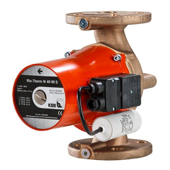
- Page 1 Hot Water Service Pump Rio-Therm N Rio-Therm N 25-30 to 80-80 Installation/Operating Manual...
- Page 2 All rights reserved. The contents provided herein must neither be distributed, copied, reproduced, edited or processed for any other purpose, nor otherwise transmitted, published or made available to a third party without KSB's express written consent. Subject to technical modification without prior notice. © KSB Aktiengesellschaft Frankenthal 01.08.2012...
-
Page 3: Table Of Contents
Contents Contents Glossary ....................5 General ....................6 Principles ......................6 Target group ..................... 6 Symbols ......................6 Safety .....................7 Key to safety symbols/markings ............... 7 General ......................7 Intended use .....................7 Personnel qualification and training ............... 8 Consequences and risks caused by non-compliance with these operating instructions ...................... - Page 4 Contents Commissioning/Start-up/Shutdown ...........19 Commissioning/start-up ................. 19 Shutdown ......................21 Operating limits ....................21 Shutdown/storage/preservation ..............22 Returning to service ..................22 Servicing/Maintenance ...............23 Servicing/inspection ..................23 Drainage/cleaning ..................23 Dismantling the pump set ................23 Trouble-shooting ................25 Related Documents ................2 6 Sectional drawing with list of components ..........26 Wiring diagrams .....................
-
Page 5: Glossary
Glossary Glossary Discharge line Pump set The line which is connected to the discharge Complete pump set consisting of pump, drive, nozzle additional components and accessories Noise characteristics Suction lift line/suction head line The noise emission to be expected, indicated as The line which is connected to the suction sound pressure level LpA in dB(A) nozzle... -
Page 6: General
(set) and serve as identification for all further business processes. identify the pump (set) and serve as identification for all further business processes. In the event of damage, immediately contact your nearest KSB service centre to In the event of damage, immediately contact your nearest KSB service centre to maintain the right to claim under warranty. -
Page 7: Safety
2 Safety 2 Safety All the information contained in this section refers to hazardous situations. DANGER 2.1 Key to safety symbols/markings Table 2: Definition of safety symbols/markings Symbol Description DANGER DANGER This signal word indicates a high-risk hazard which, if not avoided, will result in death or serious injury. -
Page 8: Personnel Qualification And Training
2 Safety ▪ Observe the maximum flow rates indicated in the data sheet or product literature (to prevent overheating, mechanical seal damage, cavitation damage, bearing damage, etc). ▪ Do not throttle the flow rate on the suction side of the pump (to prevent cavitation damage). -
Page 9: Safety Information For Maintenance, Inspection And Installation Work
2 Safety ▪ Eliminate all electrical hazards. (In this respect refer to the applicable national safety regulations and/or regulations issued by the local energy supply companies.) 2.8 Safety information for maintenance, inspection and installation work ▪ Modifications or alterations of the pump are only permitted with the manufacturer's prior consent. -
Page 10: Transport/Temporary Storage/Disposal
On transfer of goods, check each packaging unit for damage. In the event of in-transit damage, assess the exact damage, document it and notify KSB or the supplying dealer (as applicable) and the insurer about the damage in writing immediately. -
Page 11: Disposal
3 Transport/Temporary Storage/Disposal 3.5 Disposal WARNING Fluids and supplies posing a health hazard and/or hot fluids and supplies Hazard to persons and the environment! ▷ Collect and properly dispose of flushing medium and any residues of the fluid handled. ▷ Wear safety clothing and a protective mask, if required. ▷... -
Page 12: Description Of The Pump (Set)
4 Description of the Pump (Set) 4 Description of the Pump (Set) 4.1 General ▪ Non-self-priming in-line pump Pump for handling clean or aggressive fluids not chemically and mechanically aggressive to the pump materials. 4.2 Designation Example: Rio-Therm N 50-80 T Table 3: Key to the designation Code Description... -
Page 13: Design Details
4 Description of the Pump (Set) 4.4 Design details Design ▪ Maintenance-free, screw-ended or flanged wet rotor pump (glandless) with up to four speed levels. Modes of operation ▪ Open-loop control mode (n = constant) with manual setpoint Automatic functions ▪... -
Page 14: Noise Characteristics
4 Description of the Pump (Set) Discharge nozzle Plain bearing Motor Impeller Suction nozzle Motor shaft Design The pump is designed with a radial fluid inlet and a radial outlet arranged on the same axis. The impeller is rigidly connected to the motor shaft. The motor housing is equipped with a terminal box. -
Page 15: Installation At Site
5 Installation at Site 5 Installation at Site 5.1 Safety regulations DANGER Installation in potentially explosive atmospheres Explosion hazard! ▷ Never install the pump in potentially explosive atmospheres. ▷ Observe the information given in the data sheet and on the name plates of the pump system. -
Page 16: Connecting The Piping
5 Installation at Site NOTE The direction of flow of a vertically installed pump should be upwards. CAUTION Air entering the pump Damage to vertically installed pump sets whose direction of flow is downwards! ▷ Fit a vent valve at the highest point of the suction line. NOTE To prevent any impurities from collecting in the pump do not install the pump at the lowest point of the system. -
Page 17: Casing/Insulation
5 Installation at Site Thoroughly clean, flush and blow through all vessels, pipelines and connections (especially of new installations). CAUTION Welding beads, scale and other impurities in the piping Damage to the pump! ▷ Free the piping from any impurities. 5.5 Casing/insulation WARNING The pump takes on same temperature as the fluid pumped... - Page 18 5 Installation at Site up a view of the motor shaft. If the direction of rotation is incorrect, interchange any two phases. Prior to commissioning, the vent plug must be re-inserted and tightened with a suitable screwdriver. If the piping is not filled with water, the pump should only be operated for a short period of time to prevent any damage to the pump bearings (lubricated by the product pumped).
-
Page 19: Commissioning/Start-Up/Shutdown
6 Commissioning/Start-up/Shutdown 6 Commissioning/Start-up/Shutdown 6.1 Commissioning/start-up 6.1.1 Prerequisites for commissioning/start-up Before commissioning/starting up the pump set, make sure that the following conditions are met: ▪ The pump set has been properly connected to the power supply and is equipped with all protection devices. ▪... - Page 20 6 Commissioning/Start-up/Shutdown CAUTION Abnormal noises, vibrations, temperatures or leakage Damage to the pump! ▷ Switch off the pump (set) immediately. ▷ Eliminate the causes before returning the pump set to service. ✓ The system piping has been cleaned. ✓ Pump, suction line and inlet tank, if any, have been vented and primed with the fluid to be pumped.
-
Page 21: Shutdown
6 Commissioning/Start-up/Shutdown 6.1.4 Mode of operation 6.1.4.1 Open-loop control mode with manual setpoint input The pump is operated at the set speed level (characteristic curve). The required speed level is selected by turning the control knob at the control module. In this example (see illustration) the pump is operated at medium speed. -
Page 22: Shutdown/Storage/Preservation
6 Commissioning/Start-up/Shutdown 6.3.1 Ambient temperature CAUTION Operation outside the permissible ambient temperature Damage to the pump (set)! ▷ Observe the specified limits for permissible ambient temperatures. Observe the following parameters and values during operation: Table 7: Temperature of the fluid pump as a function of the ambient temperature [°C] Product temperature Ambient temperature... -
Page 23: Servicing/Maintenance
7 Servicing/Maintenance 7 Servicing/Maintenance 7.1 Servicing/inspection The circulator pumps are almost maintenance-free. If the pump has not been in operation for a prolonged period of time or if the system is severely contaminated, the rotor can become locked. The rotor can be unlocked by undoing the screwed plug, inserting a screw driver into the shaft end, and rotating the rotor. - Page 24 7 Servicing/Maintenance Depending on the pump/motor size, remove the supports from the pump set. Remove the complete pump set from the piping. 24 of 30 Rio-Therm N...
-
Page 25: Trouble-Shooting
8 Trouble-shooting 8 Trouble-shooting Pump is running but does not deliver Pump does not start up or pump running unevenly Pump running but not delivering water Noises during pump operation Table 8: Trouble-shooting A B C D Possible cause Remedy ✘... -
Page 26: Related Documents
9 Related Documents 9 Related Documents 9.1 Sectional drawing with list of components 81-59 818 814 81-22 Part No. Description Part No. Description Volute casing Impeller Plain bearing 81-22 Terminal box cover 81-59 Stator Copper windings Rotor 9.2 Wiring diagrams Single-phase (S models) PE L Fig. -
Page 27: Ec Declaration Of Conformity
10 EC Declaration of Conformity 10 EC Declaration of Conformity Manufacturer: KSB Aktiengesellschaft Johann-Klein-Straße 9 67227 Frankenthal (Germany) The manufacturer herewith declares that the product: Rio-Therm N Series code: 1201-1752 ▪ is in conformity with the provisions of the following Directives as amended from time to time: –... -
Page 28: Index
Index Index Commissioning/start-up 19 Operating limits 7, 21 Disposal 11 Piping 16 Preservation 10, 22 Product description 12 Fault 25 Return to supplier 10 Returning to service 22 Intended use 7 Safety 7 Safety awareness 8 Misuse 8 Scope of supply 14 Shutdown 22 Start-up 20 Storage 10, 22... - Page 30 KSB Aktiengesellschaft 67225 Frankenthal • Johann-Klein-Str. 9 • 67227 Frankenthal (Germany) Tel. +49 6233 86-0 • Fax +49 6233 86-3401 www.ksb.com...
Need help?
Do you have a question about the Rio-Therm N Series and is the answer not in the manual?
Questions and answers