Table of Contents
Advertisement
Quick Links
Advertisement
Table of Contents

Related Manuals for KSB Rotex


Summary of Contents for KSB Rotex
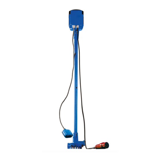
- Page 1 Grey Water and Condensate Pump Rotex Installation/Operating Manual...
- Page 2 All rights reserved. The contents provided herein must neither be distributed, copied, reproduced, edited or processed for any other purpose, nor otherwise transmitted, published or made available to a third party without the manufacturer's express written consent. Subject to technical modification without prior notice. © KSB SE & Co. KGaA, Frankenthal 2023-01-19...
-
Page 3: Table Of Contents
Installation at Site .......................... 18 Safety regulations............................ 18 Checks to be carried out prior to installation.................... 18 Mounting the cover plate (optional, only available for Rotex 70).............. 18 Installing the pump set .......................... 19 Connecting the piping ........................... 19 Permissible forces and moments at the pump nozzles ................ 20 Electrical system.............................. 20... - Page 4 Ordering spare parts ......................... 35 7.6.2 Recommended spare parts stock...................... 35 Trouble-shooting.......................... 36 Related Documents .......................... 38 Exploded views with list of components....................... 38 9.1.1 Rotex 10, 20 ............................ 38 9.1.2 Rotex 70 ............................. 39 Wiring diagrams ............................. 40 9.2.1 Rotex D .............................. 40 9.2.2 Rotex E ...............................
-
Page 5: Glossary
Machine without drive, additional components or accessories Pump set Complete pump set consisting of pump, drive, additional components and accessories Waste water Water consisting of a combination of water discharged from households, industrial and other businesses as well as surface water. Rotex 5 of 48... -
Page 6: General
In the event of damage, immediately contact your nearest KSB service facility to maintain the right to claim under warranty. 1.2 Installation of partly completed machinery To install partly completed machinery supplied by KSB refer to the sub-sections under Servicing/Maintenance. -
Page 7: Symbols
In conjunction with one of the signal words this symbol indicates a hazard involving electrical voltage and identifies information about protection against electrical voltage. Machine damage In conjunction with the signal word CAUTION this symbol indicates a hazard for the machine and its functions. Rotex 7 of 48... -
Page 8: Safety
▪ Never open the discharge-side shut-off elements further than permitted. – The maximum flow rate specified in the technical product literature would be exceeded. – Risk of cavitation damage ▪ Observe all safety information and instructions in this manual. Rotex 8 of 48... -
Page 9: Personnel Qualification And Training
▪ If stopping the pump does not increase potential risk, fit an emergency-stop control device in the immediate vicinity of the pump (set) during pump set installation. Rotex 9 of 48... -
Page 10: Safety Information For Maintenance, Inspection And Installation
Never operate the pump (set) outside the limits stated in the data sheet and in this operating manual. The warranty relating to the operating reliability and safety of the pump (set) supplied is only valid if the equipment is used in accordance with its intended use. (ð Section 2.2, Page 8) Rotex 10 of 48... -
Page 11: Transport/Storage/Disposal
▷ Observe the applicable local accident prevention regulations. ▷ Use suitable, approved lifting accessories. To transport the pump/pump set suspend it from the lifting tackle as shown. Fig. 1: Transporting a Rotex pump set with a rope looped around the bottom of the motor Rotex... -
Page 12: Storage/Preservation
4. Always complete and enclose a certificate of decontamination when returning the pump. Indicate any safety measures and decontamination measures taken. (ð Section 11, Page 45) NOTE If required, a blank certificate of decontamination can be downloaded from the following web site: www.ksb.com/certificate_of_decontamination Rotex 12 of 48... -
Page 13: Disposal
Collect greases and other lubricants during dismantling. 2. Separate and sort the pump materials, e.g. by: - Metals - Plastics - Electronic waste - Greases and other lubricants 3. Dispose of materials in accordance with local regulations or in another controlled manner. Rotex 13 of 48... -
Page 14: Description Of The Pump (Set)
▪ Level control with float switch Installation depth [cm] 100, 170 Drive Three-phase motor Single-phase AC motor Rotex size 70 cannot be used for condensate. Rotex size 70 is only available up to an installation depth of 100 cm. Rotex 14 of 48... -
Page 15: Name Plate
4 Description of the Pump (Set) 4.4 Name plate KSB SE & Co. KGaA Johann-Klein-Straße 9 67227 Frankenthal Deutschland Fig. 2: Rotex name plate (example) Type series, size Flow rate (Q - Q min. max. Principles of construction and Year/week of construction... -
Page 16: Configuration And Function
4 Description of the Pump (Set) Automation ▪ Level control ▪ Pump started/ stopped automatically depending on the fluid level Rotex 10, 20: ▪ Displacement weight with cable pull float switch control Rotex 70: ▪ Float switch 4.6 Configuration and function Fig. 3: Rotex... -
Page 17: Noise Characteristics
▪ Alarm switchgear ▪ Other accessories on request 4.9 Dimensions and weights Dimensions Refer to the Dimensions section for information on the dimensions. (ð Section 9.3, Page 42) Weights Table 5: Weight [kg] Rotex [kg] 10/100 D 10/100 E 10/170 D 10/170 E 20/100 D 20/170 E... -
Page 18: Installation At Site
As a minimum, the nominal diameter of the vent lines must match that of the inlet lines. 5.3 Mounting the cover plate (optional, only available for Rotex 70) 1. Fix the angular frame into the wall of the pit near the edge. -
Page 19: Installing The Pump Set
1. Thoroughly clean, flush and blow through all vessels, pipelines and connections (especially of new installations). 2. Before installing the pump in the piping, remove the flange covers on the suction and discharge nozzles of the pump. Rotex 19 of 48... -
Page 20: Permissible Forces And Moments At The Pump Nozzles
5.7 Electrical system 5.7.1 Electrical connection The available mains voltage must correspond to the voltage stated on the name plate. Table 6: Fuses for the power cable [A] Rotex Fuse size 10 D, 20 D 10 E, 20 E 70 D 70 E The pump set is supplied complete with power cable and plug. -
Page 21: Motor Protection
NOTE If the thermal motor protection trips the pump several times in a row, contact KSB Service. Rotex D The motor is protected by temperature switches installed in the winding. They interrupt the current when the maximum permissible winding temperature is reached and thus trip the pump. -
Page 22: Fitting And Setting The Level Control Equipment
5 Installation at Site 5.8 Fitting and setting the level control equipment 5.8.1 Displacement weights (Rotex 10, 20) 81-36 99-8.1 59.18 59-11.1 485.1 99-8.2 59-11.2 485.2 ~ 40 Fig. 4: Fitting the level control equipment ü Microswitch 838 and thread 99-8.1 have been fitted in terminal box 81-36 at the factory. -
Page 23: Float Switch (Rotex 70)
7. Run the end of thread 99-8.2 between disc 550 and discharge casing 107 and tie a knot into it. Make sure that the thread has sufficient slack (approx. 40 mm) for the actuation of microswitch 838. 8. Cut off the excess length of thread 99-8.2. 5.8.2 Float switch (Rotex 70) 81-36 73-2 412.2 30°... -
Page 24: Checking The Direction Of Rotation
The pump set is supplied for the correct direction of rotation. The direction of rotation need not be checked. Rotex D The pump set is wired at the factory in such a way that the direction of rotation of the pump is correct provided that the mains' phase sequence (building supply mains) is correct. -
Page 25: Commissioning/Start-Up/Shutdown
ü The system piping has been cleaned. ü The pump and the inlet tank, if any, have been vented and primed with the fluid to be handled. ü The lines for priming and venting have been closed. Rotex 25 of 48... -
Page 26: Operating Limits
Damage to the pump set by cavitation! ▷ Never allow the fluid level to drop below the specified minimum. Minimum Rotex 10, 20: 150 mm above the bottom edge of the casing; if handling condensate 400 mm Rotex 70: 100 mm above the bottom edge of the casing Maximum 100 mm below the plate... - Page 27 Temperature difference 6.2.1.4 Temperature of fluid handled CAUTION Incorrect fluid temperature Damage to the pump (set)! ▷ Only operate the pump (set) within the temperature limits indicated. Table 8: Temperature of fluid handled Rotex Temperature Min. Max. [°C] [°C] 10, 20 When pumping fluids with a temperature exceeding 70 °C, a minimum head of 8 m...
-
Page 28: Frequency Of Starts
Damage to the pump (set)! ▷ The maximum permissible deviation in supply voltage is 10 % of the rated voltage indicated on the name plate. ▷ The maximum permissible voltage difference between the individual phases is 1 %. Rotex 28 of 48... -
Page 29: Shutdown/Storage/Preservation
▷ As soon as the work is completed, properly re-install and re-activate any safety- relevant devices and protective devices. NOTE If the equipment has been out of service for more than one year, replace all elastomer seals. Rotex 29 of 48... -
Page 30: Servicing/Maintenance
NOTE All maintenance work, service work and installation work can be carried out by KSB Service or authorised workshops. For contact details refer to the enclosed "Addresses" booklet or visit "https://www.ksb.com/en-global/contact" on the Internet. -
Page 31: Visual Inspection
Check for any deposits. Clean it as required. Make sure that the overflow hole A 17 at support column 712 is free at all times and not clogged or covered with incrustations. (ð Section 9.1, Page 38) More often if required and depending on the application Rotex 31 of 48... -
Page 32: Drainage / Cleaning
CAUTION Contact of O-ring with graphite or similar material Fluid could escape! ▷ Do not coat O-ring with graphite or similar material. ▷ Use animal fats or lubricants based on silicone or PTFE. ▪ Assembly aids Rotex 32 of 48... -
Page 33: Reassembling The Pump Section
Tightening torques For reassembly, tighten all screws and bolts as indicated. 7.4.2 Reassembling the pump section 7.4.2.1 Reassembling the pump section (Rotex 10, 20) 1. Fasten discharge casing 107 with casing wear ring 502 to bearing housing 350. 2. Tighten hexagon head bolts 901 fastening discharge casing 107. -
Page 34: Removing The Pump Set From The Piping
7.5.3 Dismantling the pump section 7.5.3.1 Dismantling the pump section (Rotex 10, 20) ü The pump set has been removed from the system. (ð Section 7.5.2, Page 34) ü The pump set has been placed in a clean and level assembly area. -
Page 35: Spare Parts Stock
▪ Part No. and description ▪ Quantity of spare parts ▪ Shipping address ▪ Mode of dispatch (freight, mail, express freight, air freight) 7.6.2 Recommended spare parts stock It is not necessary to keep spare parts on stock. Rotex 35 of 48... -
Page 36: Trouble-Shooting
- Motor is not running because the level control ▪ Check the level control equipment. ✘ equippment is defective/has jammed. ▪ Contact KSB Service, if necessary. ✘ - Motor is not running because the winding or ▪ Contact KSB Service. - Page 37 - Excessive temperature of the fluid handled ▪ Reduce temperature. ✘ ✘ ✘ ✘ Defective radial bearing in the motor. ▪ Contact KSB Service. ✘ Impermissible air or gas content in the fluid ▪ Contact KSB. handled ✘ Aggressive or abrasive fluid ▪...
-
Page 38: Related Documents
9 Related Documents 9 Related Documents 9.1 Exploded views with list of components 9.1.1 Rotex 10, 20 Fig. 6: Exploded view - Rotex 10, 20 ( ) = Not available as a separate spare part Table 11: List of components Part No. Description Part No. -
Page 39: Rotex 70
Motor 99-8.2 Thread 81-2 Plug A 17 Overflow hole 9.1.2 Rotex 70 Fig. 7: Exploded view - Rotex 70 ( ) = Not available as a separate spare part Table 12: List of components Part No. Description Part No. Description Volute casing 81-22 Terminal box cover... -
Page 40: Wiring Diagrams
9 Related Documents 9.2 Wiring diagrams 9.2.1 Rotex D Fig. 8: Wiring diagram Rotex D Microswitch or float switch CEE plug Klixon Contactor 9.2.2 Rotex E Fig. 9: Wiring diagram Rotex E Microswitch or float switch Shockproof plug Rotex 40 of 48... - Page 41 9 Related Documents Overcurrent circuit breaker Run capacitor Main winding Auxiliary winding Rotex 41 of 48...
-
Page 42: Dimensions
9 Related Documents 9.3 Dimensions 9.3.1 Rotex 10, 20, 70 Fig. 10: Dimensions a) Rotex 70 b) Rotex 10, 20 Minimum water level (stop level) Rotex 10, 20: 150 mm Rotex 70: 100 mm Maximum water level (start-up level) Rotex .../170: ≥ 1000 mm If handling condensate: 400 mm... - Page 43 110 220 242 1050 1700 500 560 20/100 Rp 2 1370 1076 117 110 240 270 180 1000 500 560 20/170 Rp 2 2092 1798 117 110 240 270 1050 1700 500 560 Rp 1 1/4 1342 1046 97 590 1000 500 560 33,8 660 Rotex 43 of 48...
-
Page 44: Eu Declaration Of Conformity
10 EU Declaration of Conformity 10 EU Declaration of Conformity Manufacturer: KSB SE & Co. KGaA Johann-Klein-Straße 9 67227 Frankenthal (Germany) The manufacturer herewith declares that the product: Rotex 70/10/20 Serial number: 2022w01 - 2024w52 ▪ is in conformity with the provisions of the following directives / regulations as amended from time to time: –... -
Page 45: Certificate Of Decontamination
We confirm that the above data and information are correct and complete and that dispatch is effected in accordance with the relevant legal provisions....................................Place, date and signature Address Company stamp Required field Rotex 45 of 48... -
Page 46: Index
Fluid handled Density 28 Frequency of starts 28 Impeller type 15 Installation 15, 18 Installation at site 18 Intended use 8 Key to safety symbols/markings 7 Order number 6 Other applicable documents 6 Partly completed machinery 6 Permissible forces at the pump nozzles 20 Preservation 12 Product description 14 Rotex 46 of 48... - Page 48 KSB SE & Co. KGaA Johann-Klein-Straße 9 • 67227 Frankenthal (Germany) Tel. +49 6233 86-0 www.ksb.com...
Need help?
Do you have a question about the Rotex and is the answer not in the manual?
Questions and answers