Table of Contents
Advertisement
Quick Links
Advertisement
Table of Contents

Subscribe to Our Youtube Channel
Related Manuals for Fluke 6270A


Summary of Contents for Fluke 6270A
- Page 1 6270A Pressure Controller/Calibrator Operators Manual October 2014 Rev. 2, 6/17 © 2014-2017 Fluke Corporation. All rights reserved. Specifications are subject to change without notice. All product names are trademarks of their respective companies.
- Page 2 Fluke authorized resellers shall extend this warranty on new and unused products to end-user customers only but have no authority to extend a greater or different warranty on behalf of Fluke. Warranty support is available only if product is purchased through a Fluke authorized sales outlet or Buyer has paid the applicable international price.
-
Page 3: Table Of Contents
Table of Contents Title Page Introduction .................... 1 Contact Fluke Calibration ..............1 Safety Information ................. 2 Symbols ....................3 The Product Manual Set ................ 3 Specifications ..................4 Control Specifications ................6 Pressure Measurement Specifications ..........6 PM200 Modules ................. 7 PM600 Modules ................. - Page 4 6270A Operators Manual Set Target Pressure (Setpoint) ............37 Step Pressure Up or Down ..............37 Jog Pressure ..................38 Vent and Abort ................... 38 Pressure Measurement ..............39 Pressure Control Settings ..............40 Control Modes ................... 40 Dynamic Control Mode ..............40 Static Control Mode ................
- Page 5 Contents (continued) Remote Interface ................71 Troubleshooting ..................71 Error Codes ................... 74 User-Replaceable Parts and Accessories ..........76...
- Page 6 6270A Operators Manual...
-
Page 7: Introduction
Pressure Control Module (PCM) to regulate pressure output. The touchscreen display features a multi-language user interface (UI). See Instrument Setup Menu for more information. Contact Fluke Calibration To contact Fluke Calibration, call one of the following telephone numbers: • Technical Support USA: 1-877-355-3225 •... -
Page 8: Safety Information
6270A Operators Manual Safety Information A Warning identifies conditions and procedures that are dangerous to the user. A Caution identifies conditions and procedures that can cause damage to the Product or the equipment under test. Warnings To prevent possible electrical shock, fire, or personal injury: •... -
Page 9: Symbols
6270A Remote Programmers Guide (provided at the Fluke Calibration website) To order, refer to the Fluke Calibration Catalog or contact a Fluke Calibration sales representative. See Contact Fluke Calibration. This manual provides complete information to install and operate the Product... -
Page 10: Specifications
Calibration and Repair Information If calibration or repair is needed during the warranty period, contact an authorized Fluke Calibration Service Center to arrange for repair (see Contact Fluke Calibration). Please have the Product information ready such as the purchase date and serial number to schedule the repair. - Page 11 Pressure Controller/Calibrator Specifications Dimensions Height..........147 mm (5.78 in) Width ........... 452 mm (17.79 in) Depth ..........488 mm (19.2 in) Rack Mount Dimensions ..... 3U-19-inch rack Chassis Pressure Limits Supply Port ........23 MPa (3300 psi) gauge Test Port ..........20 MPa (3000 psi) gauge Reference Port ........
-
Page 12: Control Specifications
6270A Operators Manual Control Specifications Control Precision (Dynamic Mode) PM200-BG2.5K........0.005 % Range Span All other Ranges ......... 0.001 % Range Span Control Turndown ....... 10:1 (Typical) Control turndown is defined as the relationship between the provided supply pressure and the appropriate supply pressure for the range. -
Page 13: Pm200 Modules
Pressure Controller/Calibrator Control Specifications PM200 Modules 1-Year Model Range (SI Units) Range (Imperial Units) Measurement Mode Specification (%FS) PM200-BG2.5K -2.5 kPa to 2.5 kPa gauge 0.20 % -10 inH₂0 to 10 inH₂0 PM200-BG35K -35 kPa to 35 kPa -5 psi to 5 psi gauge 0.05 % PM200-BG40K... -
Page 14: Pm600 Modules
6270A Operators Manual PM600 Modules The product specifications describe the Absolute Instrumental Uncertainty of the Product. The product specifications includes linearity, hysteresis, repeatability, resolution, reference standard measurement uncertainty, 1 year stability, and temperature effects from 15 to 35 °C. The product specifications are provided at a 95 %, k=2, normally distributed, level of confidence. -
Page 15: Unpack The Product
Check that all items listed in Table 2 are present and have no visible damage. If it is necessary to reship the Product, use the original container. To order a new container, see Contact Fluke Calibration. Table 2. Standard Equipment Item... -
Page 16: Product Placement
6270A Operators Manual Product Placement Warnings To prevent possible electrical shock, fire, or personal injury, do not restrict access to the Product mains power cord. The mains power cord is the mains disconnecting device. If access to the power cord is inhibited by rack mounting, a properly-rated accessible mains disconnecting switch must be provided within reach as part of the installation. -
Page 17: Connect To Mains Power
The Product comes with the appropriate line power plug for the country of purchase. If a different type is necessary, refer to Table 3 and Figure 1. They list and show the mains line power plug types available from Fluke Calibration. Table 3. Line Power Cord Types Available from Fluke Calibration... -
Page 18: Access The Module Bay
6270A Operators Manual Access the Module Bay Before use, install the Pressure Control Module (PCM) and Pressure Measurement Module(s) (PMM). After the Product is properly placed (in a standard 19 inch rack or on a bench top) install the modules in the Module Bay. - Page 19 Pressure Controller/Calibrator Access the Module Bay huo001.eps Figure 2. Module Bay...
-
Page 20: Pmm Installation
6270A Operators Manual PMM Installation The PMMs are delivered in a separate box. Install the PMMs with the Product turned on or off. The PMMs can be installed in any order without the need to plug any of the unused slots. When the front panel is opened, information such as the pressure range of each module is shown after it is connected. - Page 21 Pressure Controller/Calibrator PMM Installation huo011.eps Figure 3. PMM Installation...
-
Page 22: Pcm Installation
6270A Operators Manual PCM Installation Depending upon how the Product is ordered, the PCM may come installed in the unit or be delivered in a separate box. To install the PCM: Caution To prevent damage to the sensors inside the modules, do not drop the modules. -
Page 23: Barometric Reference Module (Brm)
Pressure Controller/Calibrator Barometric Reference Module (BRM) Barometric Reference Module (BRM) For absolute measurements, a Barometric Reference Module (BRM) must be installed unless the PMM is equipped with its own barometric reference (refer to the PMM specifications). When a BRM is installed, the Absolute Measurement Mode becomes available (see Measurement Modes). -
Page 24: Supply Port
SUPPLY Port The pressure SUPPLY port must be connected to a regulated source of clean, dry air or nitrogen as directed in Specifications. Fluke Calibration recommends that tubing be at least 3 millimeters (1/8 inch) inside diameter and properly rated for the pressure. -
Page 25: Exhaust Port (Vacuum Pump If Required)
EXHAUST port. The flow of this gas can be greater than what the vacuum pump can support. When working at higher pressures, Fluke Calibration recommends that the vacuum pump be turned off and equipped with an auto-vent valve. -
Page 26: Test Port
To control these changes, Fluke Calibration recommends that the reference port (also referred to as the "test-(test minus)" or "low" port of all relevant devices be... -
Page 27: Vent Port
Pressure Controller/Calibrator Rear-Panel Manifold Pressure Connections The REF port can be sealed from atmosphere in most applications where the test times are relatively short. This isolates the port from pressure changes in the atmosphere and results in very stable pressure measurement and control. If the test times are relatively long, in addition to connecting the reference ports together, they should also be connected to a buffer tank with a large volume (size depends on application). -
Page 28: Controller Settings (Setup Menu)
6270A Operators Manual Controller Settings (Setup Menu) When the Product is first used, set the user preferences from the Setup menu. From the Main screen, touch SETUP. The UI shows the Setup menu. Setup Menu The Setup menu leads to these submenus: Measure Setup –... -
Page 29: Instrument Settings Menu
Pressure Controller/Calibrator Controller Settings (Setup Menu) Instrument Settings Menu To set user preferences, from the Instrument Setup menu, touch the Instrument Settings tab. The Instrument Settings menu is shown. The sections of the Instrument Settings menu are explained in Table 5. Note A password is required to change the Date/Time and Security parameters. - Page 30 Product prompts for the current password. Use the numeric keypad to enter the current password. To change the password over the remote interface use the CAL_PASSWD command. Note If the new password is lost, contact Fluke Calibration Customer Service. A new password will be provided.
-
Page 31: Remote Port Menu
Pressure Controller/Calibrator Controller Settings (Setup Menu) Remote Port Menu Use the Remote Port menu to change or view the USB, GPIB, RS-232, and Ethernet port settings explained in Table 6. Table 6. Remote Port Menu Description Use this menu to change the remote interface (Remote IF) to be from a Computer USB Setup or Terminal. - Page 32 Show Uncertainty • See the Tech Note Guide to Determining Pressure Measurement Uncertainty for 6270A Pressure Controller/Calibrator Pressure Modules located at http://www.Flukecal.com. This page of the menu is for information purposes only. It is useful information for the user and any technician that might work on the Product. The information on the...
-
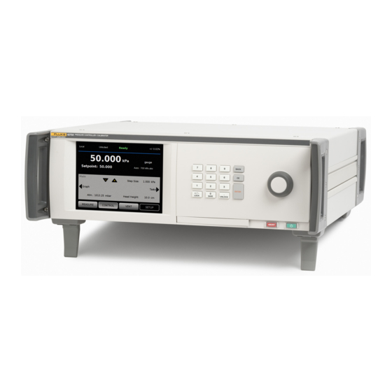
Page 33: Front-Panel Features
Pressure Controller/Calibrator Front-Panel Features Front-Panel Features This section is a reference for the front and rear panel features and the User Interface (UI) touchscreen. The front-panel features (including all controls, displays, indicators, and terminals) are shown and explained in Table 7. Table 7. - Page 34 6270A Operators Manual Table 7. Front-Panel Features (cont.) Item Description Use the Jog Wheel to make fine adjustments to the applied pressure. When turned, the applied pressure changes by the least significant digit based on the measurement resolution refer to Measurement Resolution for more information.
-
Page 35: Rear-Panel Features
Pressure Controller/Calibrator Rear-Panel Features Rear-Panel Features Rear-panel features (including all terminals, sockets, and connectors) are shown in Table 8. Table 8. Rear-Panel Features huo009.eps Item Description Switch test inputs used to connect a pressure switch to the Product for pressure switch testing. See Switch Test. ... - Page 36 6270A Operators Manual Table 8. Rear-Panel Features (cont.) Item Description IEEE-488.2 remote operation interface. Refer to the Remote Programmers Manual for more information on remote operation. IEEE-488 Connector RS-232 remote operation interface. Refer to the Remote Programmers Manual for more information on remote operation.
-
Page 37: Turn On The Product
Pressure Controller/Calibrator Turn on the Product Turn on the Product To turn on the Product, turn on the main power switch, located on the left-rear of the Product when looking at it from the front. When the Product is turned on, it takes approximately 50 seconds to complete its power-up process. - Page 38 Shows the pressure measured by the active PMM. Measurement Shows when the Controller is under remote operation by a PC. See the 6270A Remote Programmers Guide for more information. Note Local / Remote When the Product enters Remote mode, the front panel is automatically locked to prevent accidental changes.
- Page 39 Pressure Controller/Calibrator Main Menu Table 9. Main Menu (cont.) Item Indicator/Name Function Shows the measurement uncertainty based upon the uncertainty of Measurement the currently-selected PMM and the settings in the Uncertainty Setup Uncertainty menu. See Table 6. Shows the active measurement mode and opens a menu to change Measurement ...
- Page 40 6270A Operators Manual Table 10. Control Settings huo012.eps Item Indicator/Name Function The slew rate is a user-configurable control parameter to adjust how Slew Rate fast the Product controls pressure to the setpoint. Related and used only with the Static Control mode, the control limit Control Limit is used to set an upper and lower pressure limit around the Setpoint.
- Page 41 Pressure Controller/Calibrator Main Menu Table 11. Graph huo014.eps Item Indicator/Name Function Scalable graph that shows the current pressure and historical pressure Graph behavior for up to 96 hours of elapsed time. This graph is an informational tool only and cannot be saved. Zooms Magnifies the graph by adjusting the time scale.
- Page 42 6270A Operators Manual Table 12. Tasks huo013.eps Item Indicator/Name Function Opens a menu to configure and do a leak test on the system. See Leak Test Leak Test. Switch Test Preprogrammed task to test a pressure switch dead band.
-
Page 43: Operation
Pressure Controller/Calibrator Operation Operation This section explains the pressure control settings of the Product. Operating Modes The product has three operating modes: Control, Measure, and Vent. Control Mode – When in Control mode, the Product actively controls pressure as defined by the Setpoint and will keep the pressure near the Setpoint per the active control mode (see Control Modes). -
Page 44: Jog Pressure
6270A Operators Manual Jog Pressure The Jog function is most often used when calibrating mechanical gauges such as a dial gauge and the user wishes to change the pressure until the mechanical gauge indicates a cardinal point. The user can then read the higher resolution Calibrator to determine the actual pressure value when the mechanical gauge is indicating a cardinal point. -
Page 45: Pressure Measurement
Pressure Controller/Calibrator Operation .Pressure Measurement A visual measurement indicator on the UI (also known as the “Ready indicator”) indicates when pressure is stable enough to be measured. See Table 13 for a list of measurement indicators and their definitions. For the indicator to change to “Ready”, the rate of pressure change must be within the stability limits and the pressure must be inside the hold-limit range for the active pressure control mode. -
Page 46: Pressure Control Settings
6270A Operators Manual Pressure Control Settings This section explains the pressure control settings of the Product. Some of these settings can be accessed on the main screen but all are located in the Control Settings in the Setup Menu. Control Modes The Product offers two different control modes to control pressure: •... -
Page 47: Static Control Mode
Pressure Controller/Calibrator Pressure Control Settings The upper and lower dynamic hold limit for a target value of 2,000 psi is 2 psi (2,000 psi x 0.1 % = 2 psi). The Product keeps the pressure stable between 1998 psi and 2002 psi. Static Control Mode Static Control sets the pressure slightly above the target pressure value and then turns off active pressure control, see Figure 7. -
Page 48: Control Limits (Only For Static Control)
Slew Rate is a user-defined maximum pressure rate of change. The Product controls this pressure with minimum overshoot into a wide variety of external volumes at its highest slew rate. In most applications Fluke Calibration recommends that the slew rate be set at its maximum rate value. This provides the highest speed control without jeopardizing overshoot or control stability properties. -
Page 49: Unit And Custom Units
Pressure Controller/Calibrator Pressure Measurement Settings Unit and Custom Units The Product offers a large selection of standard engineering units that can be selected to satisfy a majority of calibration requirements. Table 14 lists the standard units that come with the Product. To select a unit, touch Setup>Measure Setup>Unit and select the necessary unit. -
Page 50: Measurement Modes
6270A Operators Manual Measurement Modes The three Measurement Modes on the Product are Absolute, Gauge, and Tare: Absolute Mode – An absolute pressure measurement is made in relation to a perfect vacuum. A value of 0 represents a perfect vacuum. Certain ranges of PMMs are intrinsically absolute mode measurement modules. -
Page 51: Module Selection
Pressure Controller/Calibrator Pressure Measurement Settings Module Selection The Product selects the active pressure measurement module in these different ways: Auto – This is the default setting. The Product selects the module with the lowest pressure range that is sufficient to measure the current pressure. Fast –... -
Page 52: Atmosphere
6270A Operators Manual Atmosphere Manually select the barometric reference or manually enter a barometric value from an outside source from the Atmosphere menu (Setup Menu>Measure Setup>Atmosphere). If a barometer module is installed, the Product will automatically select it as the default barometric reference. To change the barometric reference, select the module and unit from the Atmosphere menu. -
Page 53: Tasks
Pressure Controller/Calibrator Tasks Tasks Tasks are pre-programmed routine functions that quickly perform common tests and tasks. The tasks are: Leak Test, Switch Test, Exercise, Program, CPS Cleanout and CPS Purge. Note CPS tasks are greyed out and disabled if the CPS is not turned on in the settings. -
Page 54: Switch Test
End – Maximum Setpoint pressure for the test Rate – This is the slew rate to determine how quickly the pressure will increase or decrease. For sensitive switches, Fluke Calibration recommends a slower rate. Direction – Select whether to increase then decrease pressure (up and down), or a one time upward test (single). -
Page 55: Program
Purge (if CPS installed) Purge is a function that pressurizes and vents the test system plumbing connected to the Product. Fluke Calibration recommends that, if a liquid or particulate contaminate is expected to be present, a system purge be done before a calibration is performed. -
Page 56: Contamination Prevention System (Cps)
6270A Operators Manual Contamination Prevention System (CPS) Note Maximum working pressure (MWP) of the CPS is 20 MPa (3,000 psi.) The Contamination Prevention System (CPS) is a Product accessory used to protect the Product from contamination from the UUT. The CPS accomplishes this through these methods: •... -
Page 57: Install The Cps
Pressure Controller/Calibrator Install the CPS Install the CPS To install the CPS: 1. Place the CPS on a solid surface near the Product. The CPS is heavy enough to sit on a bench and if desired, can be bolted to a bench. 2. - Page 58 6270A Operators Manual PTFE O-Ring hwr017.eps Figure 9. Replacing M20 O-ring...
-
Page 59: P3000
Pressure Controller/Calibrator CPS Use P3000 Note The thread on the test port, and the lower part of the gauge adapters is LEFT-HANDED. The following procedure details the correct method for mounting devices using these adapters: 1. Screw the appropriate gauge adapter fully on to the UUT, see Figure 10. hwr029,eps Figure 10. - Page 60 6270A Operators Manual Note Hand-tight is sufficient. Ensure that the bottom face contacts the O-ring on the test port. hwr030.eps Figure 11. Connect Assembly to Test Port 3. To adjust the position to face forward, hold the gauge adapter and turn the instrument COUNTER-CLOCKWISE, so that it faces forward, see Figure 12.
-
Page 61: Test Port Insert
Pressure Controller/Calibrator CPS Use 4. Hold the instrument steady, while turning the gauge adapter COUNTER-CLOCKWISE until it pulls down onto the O-ring, see Figure 13. hwr032,eps Figure 13. Tighten Gauge Test Port Insert For devices with 1/8 BSP or NPT mounting threads, the diameter of the thread is very close to the effective sealing diameter of the O-ring fitted to the test port. -
Page 62: Disconnect The Cps
Test Port 4542465 To calibrate panel-mounted gauges with pressure connections in the rear, use an Angle Adapter such as the Fluke P5543. The Product operates the CPS without any further interaction required by the operator. Disconnect the CPS To disconnect the CPS, ensure that the system is vented then disable the CPS in the settings. -
Page 63: Configure The Driver
Pressure Controller/Calibrator Configure the Driver Configure the Driver Turn the CPS and/or isolation valve accessories on from the Instrument Setup menu (Setup>Instrument Setup). Both require the correct pneumatic connections and electrical connections. Touch the External 24V tab to see or set the state of the external drivers. - Page 64 6270A Operators Manual In these primary functions, the solenoid drive is modulated to reduce power consumption during continuous use. Figure 17 shows the status of the drivers. • On is designated by a light green indicator (DRV4) • Off is designated by a dark green indicator (DRV1, DRV2, DRV3) huo011.bmp...
-
Page 65: Driver Electrical Connections
Pressure Controller/Calibrator Configure the Driver Driver Electrical Connections The CPS uses DRV1, DRV2, and DRV3 on the Product. For more information about the CPS, see Contamination Prevention System (CPS). For typical connections, see Figure 18. huo033.eps Figure 18. Driver Connections... -
Page 66: External Isolation Valve
6270A Operators Manual External Isolation Valve The isolation valve accessory isolates the Product from the external test port and connects to DRV4. Once installed, make sure to turn on the isolation valve function in the UI as detailed in prior section. - Page 67 Pressure Controller/Calibrator External Isolation Valve huo032.eps Figure 19. External Isolation Valve Connection...
-
Page 68: System Stacking
2. Install the Product into a rack that allows access to the rear panel. Note The Products can be placed on top of each other, but Fluke Calibration highly recommends a rack installation. A rack mount kit is available User Replaceable Parts. - Page 69 6. Connect the pressure supply line to the SUPPLY port of each Product. 7. Install the PMMs if not previously installed. Note To get the best performance from the stacked system, Fluke Calibration recommends grouping the pressure ranges together logically by pressure ranges with the highest ranges in the primary unit.
-
Page 70: Operation
6270A Operators Manual Terminating Resistor Primary T-Splitter Isolation Valve High System Communication T-Splitter Auxiliary 1 Pneumatic T Splitter Isolation Valve High System Communication Auxiliary 2 T-Splitter Terminating Resistor Isolation Valve High huo023.eps Figure 20. System Stacking Connections Operation All operation of the stacked system is done through the Primary controller either with the front panel or remotely. - Page 71 Pressure Controller/Calibrator Operation Primary Auxiliary 1 Auxiliary 2 huo028.eps Figure 21. Primary and Auxiliary Controllers...
-
Page 72: Maintenance
This section explains routine operator maintenance necessary to keep the Product in optimal condition. For intensive maintenance tasks, such as troubleshooting or repair, see the 6270A Service Manual. The Service Manual also contains the calibration adjustment procedures. See Contact Fluke Calibration for more information. -
Page 73: Clean The Exterior
Pressure Controller/Calibrator Maintenance Table 16. Replacement Fuses Fuse Description Fluke Part Number FUSE 2A 250V LONGSB 5X20MM 1297149 huo027.eps Figure 22. Access the Fuse Clean the Exterior To clean the Product, wipe it with a cloth that is lightly dampened with water or mild detergent. -
Page 74: Manifold Replacement
6270A Operators Manual Manifold Replacement The rear-panel manifolds can be easily changed while retaining their connections. For example, if the Product is in a rack and must be removed for service, the manifold can be taken out of the Product while all necessary hoses and inputs are left connected. -
Page 75: Reset Controller Settings
Pressure Controller/Calibrator Reset Controller Settings Reset Controller Settings Some of the Setup menus have a reset button that reset the settings on the current menu to the default values. Reset only resets the settings on the screen being viewed and no others. This is a helpful troubleshooting tool in case an accidental change was made to the values. -
Page 76: Measure
6270A Operators Manual Measure The Measure diagnostics menu provides information on each PMM connected: PMM – This is the PMM range and name. Pressure – This is the pressure measured by the sensor in the PMM. Temperature – This is the ambient temperature inside the PMM. The temperature inside the PMM can be as much as 5 °C higher than room... -
Page 77: Remote Interface
• Transmit • Fault Troubleshooting Table 17 explains minor troubleshooting issues. For issues outside of the scope of this section, the Product may require service. See How to Contact Fluke Calibration. Table 17. Troubleshooting Problem Probable Cause Action Electrical Problems Not plugged in Verify Product is plugged in and power is available. - Page 78 Apply proper supply pressure. supply enter control mode Door not closed Make sure the front panel is closed. Internal door- Check the sensor. Send the Product to Fluke Calibration for close sensor repair. failed System in remote operation mode Verify front panel is closed, verify the USB connection to Door not closed front panel is proper, verify Product is installed.
- Page 79 Pressure Generation or Indication Problems Pressure Verify pressure supply, perform leak check. supply too low Leak Verify Test port is leak tight. Valves require Send the Product to Fluke Calibration for repair. Product does not service reach target Target pressure pressure set higher than Install a PMM with the appropriate range.
-
Page 80: Error Codes
6270A Operators Manual Error Codes If an error occurs during Product operation or control, an error message is shown on the display. Errors can be caused by: • Incorrect control that uses the front panel, (for example, attempts to force a prohibited mode or overloading of output terminals) •... - Page 81 Pressure Controller/Calibrator Error Codes Table 18. Error Codes (cont.) Error Number Error Message Pressure Overrange Case Pressure Overrange Automatic Vent Supply Pressure Low Sensor Communication Sensor Calibration Lost Zero Aborted Factory Data Lost Calibration Mode Required Waiting for Calibration Pressure Too High Solenoid Over-Temperature Control Sensor Out of Range Controller Communication...
-
Page 82: User-Replaceable Parts And Accessories
4362094 Mains Power Cord - Denmark 2477031 Mains Power Cord - Brazil 3841347 6270A Safety Information 4454642 6270A User Documentation CD 4454992 Y6270 Rack-mount Kit Instruction Sheet 4456631 PCM installation Tool 4628864 PCM Module STD-20M; Pressure Control Module, Standard Turndown 4428630 ... - Page 83 Y6270 RACK MOUNT KIT, 19 IN WIDTH, 3U CASE-6270 Shipping Case, 6270A w/ CPS CASE-PMM Shipping Case, 3 PMM Modules PK-6270-NPT Lines and Fittings Kit, 6270A NPT PK-6270-BSP Lines and Fittings Kit, 6270A BSP PK-6270-7/16 Lines and Fittings Kit, 6270A 7/16-20...
- Page 84 6270A Operators Manual...
Need help?
Do you have a question about the 6270A and is the answer not in the manual?
Questions and answers