Table of Contents

Related Manuals for Fluke 6003A


Summary of Contents for Fluke 6003A
- Page 1 6003A Three Phase Power Calibrator Operators Manual July 2014 © 2014 Fluke Corporation. All rights reserved. Specifications are subject to change without notice. All product names are trademarks of their respective companies.
- Page 2 Fluke authorized resellers shall extend this warranty on new and unused products to end-user customers only but have no authority to extend a greater or different warranty on behalf of Fluke. Warranty support is available only if product is purchased through a Fluke authorized sales outlet or Buyer has paid the applicable international price.
-
Page 3: Table Of Contents
Table of Contents Chapter Title Page Introduction ..................1-1 Introduction .................... 1-1 Contact Fluke Calibration ..............1-1 Safety Information ................. 1-2 Symbols ..................... 1-4 Protective Earth (Grounding) ............. 1-4 Features ....................1-5 Specifications ..................1-5 Input Power ..................1-5 Dimensions ..................1-5 Environment .................. - Page 4 Pulse Inputs (IN1) ................1-12 Energy Pulse Output ..............1-12 Energy ................... 1-12 Test Duration ................. 1-12 Power Quality (6003A/PQ Power Quality Option) ......1-13 Voltage and Current Sinusoidal and Rectangular Modulation Flicker Specification ............... 1-13 Harmonics and Interharmonic ............1-13 Dip/Swell ..................
- Page 5 Set the Amplitude of Voltage or Current ..........4-20 Set the Phase (AC Power Only) ............4-21 Set the Frequency (AC Power Only) ..........4-22 Power Quality Modes (Available with 6003A/PQ Power Quality Option only) ................... 4-22 Set the Power in P Harmonic Mode ..........4-22 Set the Amplitude of Voltage or Current ..........
- Page 6 6003A Operators Manual Packet (Time Counting) ..............4-31 Counter (Pulse counting) ............... 4-31 Timer ..................... 4-31 Free Run (Frequency Measuring) ..........4-31 Energy Modes (Mode Softkey) ............4-32 Set the Energy in modes Edc Basic and Eac Basic ......4-32 Set the Voltage ................
- Page 7 Contents (continued) Harmonic Mode Amplitude Verification ......... 5-13 Interharmonic Mode Amplitude Verification ........5-14 Harmonic Mode Voltage Phase Verification ........5-14 Harmonic Mode Current Phase Verification ........5-14 Multimeter Voltage Verification ............5-15 Multimeter Frequency Verification ..........5-15 Multimeter Current Verification ............5-16 Calibration Adjustment Principles ............
- Page 8 6003A Operators Manual...
- Page 9 List of Tables Table Title Page 1-1. Symbols ..................... 1-4 2-1. Line Cords by Country ................2-3 3-1. The Product ....................3-2 3-2. Front Panel Interface ................. 3-3 3-3. Inputs ......................3-5 3-4. Outputs ...................... 3-6 3-5. The Display ....................3-7 3-6.
- Page 10 6003A Operators Manual viii...
- Page 11 List of Figures Figure Title Page 2-1. The Product with High-Current Adapter ............ 2-4 3-1. Numeric Entry .................... 3-12 4-1. Isolated Current Outputs ................4-39 5-1. Calibration Menu ..................5-18 5-2. Voltage AC#1 Screen ................5-19 5-3. Voltage AC#1 Write Screen ..............5-20 5-4.
- Page 12 6003A Operators Manual...
-
Page 13: Introduction
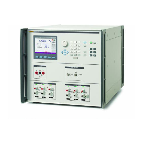
Chapter 1 Introduction Introduction The Fluke 6003A Three Phase Power Calibrator (the Product), is a precise instrument for the calibration of watt-hour meters, energy reference standards, and measuring devices used to determine the magnitude and quality of electrical power supplied to consumers. The Product can provide one, two, or three phases of electrical power and energy. -
Page 14: Safety Information
6003A Operators Manual Safety Information A Warning identifies conditions and procedures that are dangerous to the user. A Caution identifies conditions and procedures that can cause damage to the Product or the equipment under test. Warnings To prevent possible electrical shock, fire, or personal injury: •... - Page 15 Introduction Safety Information • Do not apply more than the rated voltage, between the terminals or between each terminal and earth ground. • Do not touch voltages > 30 V ac rms, 42 V ac peak, or 60 V dc. •...
-
Page 16: Symbols
Directive Annex I, this product is classed as category 9 "Monitoring and Control Instrumentation" product. Do not dispose of this product as unsorted municipal waste. Go to Fluke’s website for recycling information. Protective Earth (Grounding) The Product must be operated with a protective earth/ground connection via the protective earth/grounding conductor of the mains ac cable. -
Page 17: Features
Frequency input for counting energy meter outputs up to 1 MHz o Pulse output proportional to Energy output, up to 1 MHz • Optional Power Quality features (6003A/PQ Power Quality Option) o Non-sinusoidal voltage and current outputs with up to 63 harmonics and 1 interharmonic... -
Page 18: Environment
6003A Operators Manual Environment 5 °C to 40 °C Operating temperature 21 °C to 25 °C Calibration temperature (Tcal) range -10 °C to 55 °C Storage temperature -15 °C to 60 °C Transit temperature Warm up time 1 hour <80 %, 5 °C to 31 °C ramping linearly down to 50 % at 35 °C Safe operating max. -
Page 19: Voltage Range Limits And Burden
Introduction Electrical Specifications Voltage Range Limits and Burden 1.0000 V to 10.0001 V to 30.001 V to 70.001 V to 140.001 V to 280.001 V to Range 10 V 30 V 70 V 140 V 280 V 600 V Maximum Burden Current 141 mA 283 mA 424 mA... -
Page 20: Voltage Dc
6003A Operators Manual Voltage DC 1-Year Specification, Tcal ±2 °C ± (% of output + V) Range 1.0000 V to 10.0000 V 0.015 1 mV 10.0001 V to 30.0000 V 0.015 3 mV 30.001 V to 70.0000 V 0.015 7 mV 70.001 V to 140.000 V... -
Page 21: Current Sine Amplitude
Introduction Electrical Specifications Current Sine Amplitude 1-Year Specification, Tcal ±2 °C ±(% of output + A) Range (Amps) Frequency 60 µA 15 Hz to 40 Hz 0.021 30 µA 8.000 mA to 40 Hz to 70 Hz 0.0175 300.000 mA 60 µA 70 Hz to 1 kHz 0.021... -
Page 22: Current Output Isolation (High Or Low Terminal)
6003A Operators Manual Current Output Isolation (high or low terminal) 450 V peak maximum above earth ground. The current output terminals must only be energized by the Product Voltage output terminals. Voltage from the Current Terminals (DC and Sine Wave Only) Range Limits and Impedances 1.000 mV to... -
Page 23: Voltage To Voltage Phase
Introduction Electrical Specifications Voltage to Voltage Phase For All Voltage Ranges (1 V to 600 V) 1-Year Specification, Tcal ±2 °C Frequency 0.01 ° 15 Hz to 70 Hz 0.1 ° 70.001 Hz to 400 Hz 0.4 ° 400.001 kHz to 1 kHz Power The power specifications below are valid for sinusoidal outputs for voltage, current, and frequencies shown. -
Page 24: Sinusoidal Power Specification At 40 Hz To 70 Hz, Power Factor 0.5 (%)
Max frequency 10 kHz Input low level max 0.8 V Input low level min 3.5 V Energy (6003A/E Energy Option) Pulse Inputs (IN1) Max frequency 1 MHz (400 Hz with Input Filter On) Min pulse width 500 ns Max counts... -
Page 25: Power Quality (6003A/Pq Power Quality Option)
For a given modulation %, the output signal swings between (output setting + modulation %) and (output setting -modulation %). setting + ½ ∆V/V %) and (output setting - ½ ∆V/V%). To get the same modulation as the 6100 series, set the 6003A modulation to ½... -
Page 26: Dip/Swell
6003A Operators Manual Dip/Swell Although Dips and Swells are primarily voltage phenomena, the Product provides the same facility on its current output. AC voltage range 0.1 V to 280 V AC current range 1 mA to 30 A Amplitude accuracy 0.2 % of range... -
Page 27: Installation
Instructions for cable connections, other than line power connection, can be found in the subsequent chapters of the manual: • Voltage and current output connections and instructions for use of the 6003A test cable set are in Chapter 4. •... -
Page 28: Placement
6003A Operators Manual Placement The Product is to be used in controlled electromagnetic environments such as calibration and measurement laboratories. R.F. transmitters, such as cell phones, are not be used in close proximity to the Product. The Product is suitable for bench top use. Make sure there is sufficient space on the rear panel to allow adequate ventilation. -
Page 29: Connect To Line Power
1998198 2238680 Japan (no plug fitted) 1998211 Preparation for Operation Inspect Package Contents, Installation Location The basic package includes these items: 6003A Three Phase Power Calibrator (main unit) • Mains power cord • Spare fuse • Printed Safety Information •... -
Page 30: Installation Power And Location
6003A Operators Manual Installation Power and Location laboratory instrument which has parameters guaranteed at Tcal ±2 °C. Before The Product should be powered by 230 V/115 V – 50/60 Hz mains. It is a powering on the Product, place it on a level surface. Do not cover the fan openings on the rear panel. -
Page 31: Power-On
Installation Preparation for Operation Power-on Before you connect the Product to mains power, check the position of the mains voltage selector located on the rear panel. To power on the Product: • Plug the female end of the power cord into the connector located on the rear panel and connect the male end of the power cord to a wall outlet. - Page 32 6003A Operators Manual...
-
Page 33: Features And Basic Operation
Chapter 3 Features and Basic Operation Introduction This chapter is a reference for the functions and locations of the Product front and rear-panel features. Brief descriptions of each feature for quick access are also provided. Please read this information before operating the Product. Front-panel operation instructions are provided in Chapter 4. - Page 34 6003A Operators Manual Table 3-1. The Product hoa003.eps Number Description Front Panel Interface Inputs Outputs...
- Page 35 Features and Basic Operation Front-Panel Features Table 3-2. Front Panel Interface hoa004.eps Number Description The Display. See Table 3-5 for a complete explanation. Rotary Knob – The knob has several functions. Push in the knob to edit the main display of each function.
- Page 36 6003A Operators Manual Table 3-1. Front Panel Interface (cont.) Number Description P, E, V, and I buttons put the Product into one of its four functions: Power, Energy, Voltage, or Current. When a function is changed, the parameters of the respective function are ...
- Page 37 Multimeter measurement is available in the Power, Voltage, and Current functions. Auxiliary Input - IN1 (active with 6003A/E Energy Option) is a frequency counter that counts the pulses from an energy meter. The meter constant is set in the Energy function display.
- Page 38 6003A Operators Manual Table 3-4. Outputs hoa006.eps Number Description Voltage Output - Voltage outputs Hi and Lo terminals. Active outputs are selected in either the Main Menu or in the Power Extended modes. The Lo terminals can be grounded using the Main Menu, or allowed to float up to 20 V peak.
-
Page 39: The Display
Features and Basic Operation Front-Panel Features The Display The display is explained in Table 3-5. Table 3-5. The Display hoa009.eps Item Description Information Line - Shows the selected function (Pac Basic - AC Power basic mode), Time and Date, and Remote control state (Local - keyboard, Remote - computer). Main Value - The main output value is shown with the unit and indication of ac or dc (icon). - Page 40 6003A Operators Manual Table3-5. The Display (cont.) Item Description Outputs State - Window shows which phases are on (one to three phases) when in OPERATE, and also shows the red danger voltage symbol when any output voltage is ≥50 V.
-
Page 41: Rear Panel
Features and Basic Operation Front-Panel Features Rear Panel The rear panel is explained in Table 3-6. Table 3-6. Rear Panel hoa007.eps Number Explanation Forced air ventilation hole #1 (exhaust for Channel 1) Forced air ventilation hole #2 (exhaust for Channel 2) ... -
Page 42: Basic Operation
Instrument outputs, useful to calibrate the Product. Enabled only by remote control. Energy pulse output (active with 6003A/E Energy Option): Energy pulse output from the Product. Frequency of pulses is proportional to the power generated by ... -
Page 43: Setting The Value Of The Output Signal
Features and Basic Operation Basic Operation The state of the Product can be changed with the buttons located on the front panel in one of the subsequent ways: 1. Change of function by pushing one of the direct function buttons After you push one of the buttons (, , , ) the Product switches to the selected function and sets the last setup parameters for that function. -
Page 44: Entry Of The Value With The Numeric Keyboard
6003A Operators Manual Entry of the Value with the Numeric Keyboard Use the numeric keypad to select the necessary value. After the first digit is entered, the input box is shown. The name of edited parameter is in the upper row of the input box. -
Page 45: Entry Of The Value With The Rotary Knob
Features and Basic Operation Basic Operation Entry of the Value with the Rotary Knob • Push the rotary knob. The display now includes a cursor that points to the active digit. • Turn the rotary knob to change the active digit to another value. •... -
Page 46: Control Sequence When The Output Voltage Is >100 V Is Selected
6003A Operators Manual • The output voltage is changed to be >280 V while the current outputs are floating. This occurs if an output value that is <280 V is changed to a new value >280 V and current outputs are not grounded (GndI Off). The Product disconnects the output terminals and grounds the current terminals. -
Page 47: Front-Panel Operation
Before the procedures in this chapter are done, familiarize yourself with the front- panel controls, displays, and terminals. These are identified and described in detail in Chapter 3. For information about the Product remote commands, see the 6003A Remote Programmers Manual. Warning The Product can supply lethal voltages. Do not make connections to the output terminals when any voltage is present. -
Page 48: Set The Language On The Display
6003A Operators Manual Set the Language on the Display The Product has a display that uses either English or Chinese. To set the Product to the preferred language: 1. Push to enter the Setup menu. 2. Two softkeys are shown under the graphical display. -
Page 49: Setup Menu (Main Menu)
Front-Panel Operation Setup Menu (Main Menu) Setup Menu (Main Menu) The Product lets you set other, less frequently used, parameters. The Setup menu is used to set these parameters. Push to open the Setup menu. If output terminals are connected, they will be disconnected and the subsequent display is shown: hoa001.jpg Push ... -
Page 50: General Menu
Note The calibration code should be written down if changed. If the calibration code is lost, the Product will need to be sent to Fluke Calibration. 5. Time sets the real time. This parameter can be changed with the cursor buttons, Rotary Knob, or numeric keypad. -
Page 51: Interface Menu
0 to 30. Push the Write softkey to set the address and return to the Interface menu. Address 02 is set by Fluke Calibration as the default. Baud rate sets the communication speed used by the USB interface. 1200, 2400, 4800, 9600, 19200, 38400, 76800 or 115200 Baud can be selected. - Page 52 6003A Operators Manual Phase unit sets the unit used for setting the phase between the voltage and current output in the power and energy generation modes. Units can be selected from this list: • Deg (°) • Cos (Lead, Lag) In the Deg setting, the phase between the voltage and current output is controlled by setting a degree value.
- Page 53 The RMS value is changed by entering the new harmonic component value. Note Harmonic features are available only in the 6003A/PQ Power Quality Option. The Energy submenu contains parameters that affect energy generation: • Energy units sets the unit used for energy.
- Page 54 Note Energy features are available only with the 6003A/E Energy Option. 10. The Dip-Swell submenu has parameters that affect the Dip-Swell generation: • Dip-Swell repetition sets the repetition of Dip/Swell signal in Power Dip/Swell mode.
-
Page 55: Meter Menu
Note Dip-swell features are only available in the 6003A/PQ Power Quality Option. 11. The Voltage From Current submenu contains parameters that affect the Voltage From Current function. This function is available only in Pac and Pdc Extended modes. -
Page 56: Calibration Menu
6003A Operators Manual Calibration Menu The calibration password is necessary to access the Calibration Menu. The default calibration password is “0”. For more about calibration, see Chapter 6. Activate the Output Terminals After the Product is switched on, the output terminals are disconnected from the voltage and current amplifiers. -
Page 57: Control Sequence When Output Voltage >100 V
Front-Panel Operation Control Sequence when Output Voltage >100 V • If the output voltage exceeds 280 V while the current outputs are floating. This occurs if you change the output value to a new value >280 V and the current outputs are not grounded (GndI Off). The Product disconnects all output terminals, grounds the current terminals, and shows the subsequent message: hoa002.jpg... -
Page 58: Set The Output
6003A Operators Manual Set the Output Edit mode Parameters of the output signal can be changed in Edit mode. Only parameters shown in blue can be changed. The display can be changed to Edit mode in different ways: • Push any numeric button •... -
Page 59: Enter A Value With The Cursor Buttons
Front-Panel Operation Generating Electric Power Enter a Value with the Cursor Buttons To enter a value with the cursor buttons: 1. Push the cursor buttons. The display now includes cursor marks that point to the active digit. 2. and can be used to change the active digit. , can be used to change the position of the cursor marks. -
Page 60: Control In The Power Mode
6003A Operators Manual Control in the Power Mode • Push to set the Product to the Power mode. The display shows the subsequent data: • Value of set power in selected unit of measurement (VA, W, VAR) • Voltage at VOLTAGE OUTPUT HI-LO terminals •... -
Page 61: Power Factor Polarity (Lead/Lag Softkey)
Front-Panel Operation Generating Electric Power Power Factor Polarity (Lead/Lag Softkey) In cases where phase shift between voltage and current is shown as power factor, you can change its polarity with the Lead/Lag softkey. The Lead polarity represents a capacitive load (current before voltage). The Lag polarity represents an inductive load (voltage before current). -
Page 62: Power Modes (Mode Softkey)
6003A Operators Manual Power Modes (Mode Softkey) Output power can be generated in different power modes. For ac power modes, see Table 4-1. For dc power modes, see Table 4-2. Table 4-1. AC Power Modes Mode Name Description AC power basic mode. Phase shift between each channels output voltages are fixed (120 °... -
Page 63: Setting The Power In Modes Pdc Basic And Pac Basic
Front-Panel Operation Generating Electric Power Use the Mode softkey to open the mode selection menu. Select the necessary mode with the cursor buttons or the Rotary Knob. Push the Rotary Knob or the Select softkey to confirm the selection. Output terminals are disconnected if a new mode is selected. - Page 64 6003A Operators Manual 3. Set the Current • Change the current to change the main power value. • Repeatedly push until the current value is shown in edit mode (blue background). • The value can be set with the numeric keypad and confirmed with the mA or A softkey.
-
Page 65: Set The Power In Pdc High I And Pac High I Modes
Front-Panel Operation Generating Electric Power Set the Power in Pdc High I and Pac High I Modes In the Pdc High I and Pac High I modes, the current outputs of all channels are connected in parallel with an optional adapter. The current range is increased 3X, up to 90 A. -
Page 66: Set The Amplitude Of Voltage Or Current
6003A Operators Manual Set the Amplitude of Voltage or Current • Change the amplitude of the voltage or current to change the main power value. • Repeatedly push until the voltage (current) value is shown in edit mode (blue background). -
Page 67: Set The Phase (Ac Power Only)
Front-Panel Operation Generating Electric Power Set the Phase (AC Power Only) • If W or VAR is shown, change the phase shift to change the main power value. Change of phase does not change the output apparent power. • Repeatedly push until the phase value is shown in edit mode (blue background). -
Page 68: Set The Frequency (Ac Power Only)
Hz softkey. The value can also be set with the cursor buttons or Rotary Knob. Power Quality Modes (Available with 6003A/PQ Power Quality Option only) The subsequent modes are available only with the 6003A/PQ Power Quality Option installed. Set the Power in P Harmonic Mode Use Harmonic mode to generate a harmonic signal composed of a maximum of 63 harmonic components. -
Page 69: Set The Amplitude Of Voltage Or Current
Front-Panel Operation Power Quality Modes (Available with 6003A/PQ Power Quality Option only) Set the Amplitude of Voltage or Current Harmonic amplitude can be defined as a % of the overall RMS value, or as a % of the fundamental value. This selection is made in the Calibrator Menu, “Harmonic Components”. -
Page 70: Set The Modulation
V/V%, where its output signal swings between (output setting + ½ V/V%) and (output setting – 1/2 V/V%). To get ∆ the same modulation as the 6100 Series, set the 6003A modulation to ½ the V/V% setting of the 6100. 4-24... -
Page 71: Set The Power In P Interharmonic Mode
Front-Panel Operation Power Quality Modes (Available with 6003A/PQ Power Quality Option only) Set the Power in P Interharmonic Mode Interharmonic mode is used to generate a signal composed of the fundamental harmonic and one interharmonic component. All parameters can be defined independently for all outputs (3x voltage, 3x current). -
Page 72: Set The Amplitude (Rms Value) Of The Interharmonic Component
6003A Operators Manual Set the Amplitude (RMS Value) of the Interharmonic Component • Repeatedly push until the interharmonic value is shown in edit mode (blue background). • The value can be set with the numeric keypad and confirmed by pushing the V (mA, A) softkey. -
Page 73: Set The Amplitude (Rms Value) Of Voltage Or Current
Front-Panel Operation Power Quality Modes (Available with 6003A/PQ Power Quality Option only) The Trigger softkey starts the generation of the Dip/Swell shape. Generation can also be started (triggered) from input IN2. Dip/Swell shape is divided into five time periods and the length of these periods can be changed. The periods are shown in the box. -
Page 74: Set The Amplitude (Rms Value) Of Dip/Swell
Output terminals are disconnected if a new time is set. • Push the Channel softkey to edit the parameters of each output. Generate Electric Energy (Available with 6003A/E Energy Option installed) The Product can generate exact values of electric energy. The energy function modes provide output voltage at VOLTAGE OUTPUT HI –... -
Page 75: Control In The Energy Mode
Front-Panel Operation Generate Electric Energy (Available with 6003A/E Energy Option installed) Control in the Energy Mode • Push the on the Instrument and then push the or to select the AC or DC mode. The display shows: hoa118.jpg... -
Page 76: Power Factor Polarity (Lead/Lag Softkey)
6003A Operators Manual Push . The green LED is lit on to indicate the connection of simulated electrical energy to the output terminals. The Product starts the generation of electrical energy. The Main Value shows the generated energy. Control Mode Parameters shows running time, counted pulses or measured frequency. -
Page 77: Methods Of Energy Counting (Control)
Front-Panel Operation Generate Electric Energy (Available with 6003A/E Energy Option installed) Methods of Energy Counting (Control) There are different methods to perform an energy test. The next sections explain these methods. Packet (Time Counting) The simplest (but least accurate) method is to set the time of the energy test. In Packet mode, also known as dose mode, the power from the output terminals is timed to deliver a set amount of energy to the meter under test. -
Page 78: Energy Modes (Mode Softkey)
6003A Operators Manual Energy Modes (Mode Softkey) Output energy can be generated in different energy modes. See Tables 4-3 and 4-4: Table 4-3. AC Energy Mode Name Description AC energy basic mode. Phase shift between channels output voltages are fixed (120º and 240º). All parameters are the same for... -
Page 79: Set The Current
Front-Panel Operation Generate Electric Energy (Available with 6003A/E Energy Option installed) Set the Current The energy (power) value can be changed by changing the current. • Repeatedly push the Sel softkey until the current value appears in edit mode (blue background). -
Page 80: Set The Power In Modes Edc High I And Eac High I
6003A Operators Manual Set the Power in Modes Edc High I and Eac High I In this mode current outputs of all channels are connected in parallel (with the High Current Adapter). Current range is increased three times. Output voltage terminals are on Channel 1 only. -
Page 81: Set The Frequency (Ac Voltage Only)
52120A/COIL 6 kA. Use the Basic I mode with the 5500A/COIL, and the High I mode with the 52120/COILs. Note The 52120A/COIL 3 kA and 52120A/COIL 6 kA need to be powered with an external power supply, Fluke part number 4107239. The power supply provides 12 V dc to the cooling fan. 4-35... -
Page 82: Overload The Output Terminals
6003A Operators Manual Overload the Output Terminals When an open is detected at the current output terminals, or if the voltage at the current output terminals exceeds the Products specifications, the Product disconnects the output terminals and shows an “Output Overload” message. The... -
Page 83: Set The Current In Modes Idc High I And Iac High I
Front-Panel Operation Use the Multimeter Set the frequency (ac current only): 1. Repeatedly push until the frequency value is shown in edit mode (blue background). 2. Use the numeric keyboard to set the value and confirm by pushing the Hz softkey. -
Page 84: Product Use Tips
Product will put GndI to ON. If the output Figure 4-1 shows a typical connection of the Product to a watthour energy meter where a 6003A supplies the voltage and the Product current terminals are effectively at the same voltage as the voltage terminals. - Page 85 Front-Panel Operation Product Use Tips hoa002.eps Figure 4-1. Isolated Current Outputs 4-39...
-
Page 86: Safe Working Practices
6003A Operators Manual Safe Working Practices Warning To prevent electric shock or personal injury, remove all cables from the terminals that are not used. When connections are made to a circuit that can be energized with voltages, always ensure there are no external voltages present before connecting to the Product. -
Page 87: Use The Product To Power Energy Meters
Front-Panel Operation Product Use Tips Use the Product to Power Energy Meters The Product voltage outputs have sufficient burden current to provide power to many watthour energy meters. When doing so, you may want to continuously apply power to the energy meter during various test sequences. The Product has a Maintain Voltage Signal Parameter that allows you to do so. - Page 88 6003A Operators Manual 4-42...
-
Page 89: Verification, Calibration Adjustment, And Maintenance
0.005 % specification or better A40B-50A Can provide 12 V dc with 0.01 % Reference Calibrator specification or better, 25 mA dc Fluke 5522A or 5502A and 10 V, 15 kHz V ac 0.1 % harmonic amplitude Power Quality Analyzer specification and 0.1 degrees Tektronix PA4000 harmonic phase specification. - Page 90 Operators Manual Verification Performance Tests Note The tests shown here are for the Product that has 6003A/E Energy and 6003A/PQ Power Quality options. This section contains the recommended verification performance tests for the Product. Performance tests should be performed at least yearly to ensure conformance to the Product Specifications.
-
Page 91: Verification Performance Tests
Verification, Calibration Adjustment, and Maintenance Verification Performance Tests The Product must be in a temperature-stabilized environment a minimum of 8 hours before the performance verification test is started. Also make sure the Product is turned on at least 1 hour prior to verification. Basic Steps of the Performance Verification Test Performance verification tests consists of: •... -
Page 92: Vdc Amplitude Verification
6003A Operators Manual VDC Amplitude Verification Connect the voltage output terminals of the Product to the voltage input of the reference multimeter. Using the dc voltage function of the multimeter, set appropriate parameters to achieve the best accuracy. Function Voltage Range... -
Page 93: Modulation Mode Voltage Amplitude Verification (0 % Modulation)
Verification, Calibration Adjustment, and Maintenance Verification Performance Tests Modulation Mode Voltage Amplitude Verification (0 % Modulation) Use the reference multimeter in the AC voltage mode to make these measurements. Deviation Function Range Value Frequency Allowed 10 V 50 Hz 20 mV 10 V 10 V 60 Hz... -
Page 94: Dc Current Amplitude Verification
6003A Operators Manual DC Current Amplitude Verification 1. Connect the current outputs of the Product to the current inputs of the reference multimeter and later to the appropriate A40B current shunt. 2. Perform the dc current amplitude verification for all currents that can be measured directly by the 200 mA range of the multimeter. -
Page 95: Ac Current Amplitude Verification
Verification, Calibration Adjustment, and Maintenance Verification Performance Tests Function Range Value Deviation Allowed 10 A 10 A 3.60 mA 10 A -5.1 A 2.571 mA 10 A -10 A 3.60 mA 30 A 10.1 A 6.97 mA 30 A -10.1 A 6.97 mA 30 A 30 A... -
Page 96: Voltage From The Current Terminals Amplitude Verification
6003A Operators Manual Voltage from the Current Terminals Amplitude Verification Set the Product to output voltage from the current terminals, and connect the current output terminals of the Product to the voltage input of the reference multimeter. Deviation Function Range... -
Page 97: Modulation Mode Current Amplitude Verification (0 % Modulation)
Modulation Mode Current Amplitude Verification (0 % Modulation) Use the A40B current shunts along with the reference multimeter to make these measurements. Deviation Function Range Value Frequency Allowed 600 µA 300 mA 30 mA 50 Hz 600 µA 300 mA 300 mA 60 Hz 0.4 A... -
Page 98: Vac Amplitude Verification
6003A Operators Manual VAC Amplitude Verification Connect the input of the AC Measurement Standard to the Products voltage outputs. Deviation Function Range Value Frequency allowed 10 V 55 Hz 1.12 mV 10 V 55 Hz 1.6 mV 10 V 10 V 55 Hz 2.2 mV... -
Page 99: Power Amplitude Verification
Verification, Calibration Adjustment, and Maintenance Verification Performance Tests Power Amplitude Verification Do the power amplitude verification no later than 1 hour after doing the ac current amplitude verification and V ac amplitude verification as those measured values are used to compute the power from the Product. Connect the power analyzer to the Product output terminals. -
Page 100: Voltage Current Phase Verification
6003A Operators Manual Voltage Current Phase Verification Voltage Current Deviation Function Phase Frequency Output Output Allowed 60 ° 0.01 ° 55 Hz 60 ° 0.01 ° 20 V 55 Hz 60 ° 0.01 ° 50 V 55 Hz 60 °... -
Page 101: Harmonic Mode Amplitude Verification
Verification, Calibration Adjustment, and Maintenance Verification Performance Tests Harmonic Mode Amplitude Verification Connect the Product voltage and current output terminals to the power quality analyzer. Harmonic Deviation Function Range RMS Output Harmonic # Amplitude Allowed (% of RMS) 12.00 % 0.125 % 16.00 % 0.125 %... -
Page 102: Interharmonic Mode Amplitude Verification
6003A Operators Manual Interharmonic Mode Amplitude Verification 55 Hz fundamental Interhanrmonic Interharmonic Deviation Function Range RMS Output Frequency Amplitude Allowed 10 V 10 V 85.5 Hz 10 mV VAC-IHAR 280 V 230 V 82.5 Hz 30 V 280 mV 300 µA... -
Page 103: Multimeter Voltage Verification
1 kHz 0.05 Hz If the Fluke 5502A is used, the frequency value should be measured by the reference multimeter in parallel with the Product multimeter. The Fluke 5522A frequency specification is adequate for this test and a parallel measurement is not necessary. -
Page 104: Multimeter Current Verification
6003A Operators Manual Multimeter Current Verification Function Range Input Deviation Allowed 3.3 µA 25 mA 8.0 mA 3.5 µA 25 mA 10.0 mA 4 µA 25 mA 15.0 mA 4.5 µA 25 mA 20.0 mA 4.9 µA 25 mA 24.0 mA 3.3 µA... -
Page 105: Calibration Adjustment Principles
Verification, Calibration Adjustment, and Maintenance Calibration Adjustment Principles Calibration Adjustment Principles The Product has a built-in calibration adjustment procedure. This lets the Product be readjusted by the user. Use the buttons and menu or the remote interface to recalibrate the Product. The Product can be adjusted: •... -
Page 106: Access To The Calibration Adjustment Procedure
6003A Operators Manual • AC modulation voltage (Voltage MOD#x) calibration sets two fixed points for all voltage ranges. The frequency is 55 Hz. These calibration values are used in P Harmonic and P Interharmonic function modes. • AC modulation current (Current MOD#x) calibration sets two fixed points for all current ranges. -
Page 107: Select The Calibration Adjustment Type
Verification, Calibration Adjustment, and Maintenance Calibration Adjustment Principles If an incorrect calibration code is entered, “Bad calibration code!” shows on the display for approximately 3 seconds. 4. Use and to move the cursor through the list of calibration channels (Channels 1, 2, or 3) or Meter that is the calibration data for the internal meter). -
Page 108: Termination Of The Calibration Adjustment Process
6003A Operators Manual Use the Select softkey to choose the necessary calibration point from the list shown. Once selected, this data is shown: Write – The new calibration adjustment value is entered into the memory, the old value is replaced. The Product returns to the previous menu. -
Page 109: Calibration Points
Verification, Calibration Adjustment, and Maintenance Complete Calibration Adjustment Procedure Calibration Points Each Product function has assigned fixed-calibration points that have to be set as the product is calibrated. A summary of all calibration adjustment points are shown at the end of this section. The Product does not need calibration adjustment for: •... -
Page 110: Ac Voltage Ranges Calibration Adjustment
6003A Operators Manual AC Voltage Ranges Calibration Adjustment To adjust the calibration of the ac voltage ranges: 1. Connect the voltage input terminals of the ac measurement standard to the VOLTAGE OUTPUT HI - LO terminals of the Product. 2. Select Voltage AC#1 from the Calibration Menu. -
Page 111: Ac Current Ranges Calibration Adjustment
Verification, Calibration Adjustment, and Maintenance Complete Calibration Adjustment Procedure AC Current Ranges Calibration Adjustment To adjust the calibration of the ac current ranges: 1. Select Current AC#1 from the Calibration Menu. 2. Push the Select softkey to confirm. Current shunts should be used for all ac current range calibration adjustments. - Page 112 6003A Operators Manual Table 5-3. Current AC Function (Current AC#x) Nominal Value [A] Set Limits [A] Range [A] 10 µV 30 mA 300 mV 15 µV 300 mA 300 mV 30 µV 300 mA 50 µV 100 µV 100 µV 200 µV...
-
Page 113: Dc Voltage Ranges Calibration Adjustment
Verification, Calibration Adjustment, and Maintenance Complete Calibration Adjustment Procedure DC Voltage Ranges Calibration Adjustment To adjust the calibration of the dc voltage ranges: 1. Select Voltage DC#1 from the Calibration Menu. 2. Push the Select softkey to confirm. 3. Switch the Product output terminals to Operate. 4. -
Page 114: Dc Current Ranges Calibration Adjustment
6003A Operators Manual DC Current Ranges Calibration Adjustment To adjust the calibration of the dc current ranges: 1. Select Current DC#1 from the Calibration Menu. 2. Push the Select softkey to confirm. adjustments except for ±30 mA outputs which should be measured directly by Current shunts should be used for all dc current range calibration the reference multimeter. - Page 115 Verification, Calibration Adjustment, and Maintenance Complete Calibration Adjustment Procedure Table 5-5. Current DC Function (Current DC#x) (cont.) Nominal Value [A] Set Limits [A] Range [A] 250 µA 500 µA 500 µA 500 µA 500 µA 1 mA 1.5 mA 1 mA 1.5 mA 5-27...
-
Page 116: Ac Voltage Modulation Ranges Calibration Adjustment (P Harmonic, P Interharmonic Modes)
6003A Operators Manual AC Voltage Modulation Ranges Calibration Adjustment (P Harmonic, P Interharmonic Modes) To adjust the calibration of the ac voltage modulation ranges: 1. Select Voltage MOD#1 from the Calibration Menu. 2. Push the Select softkey to confirm. 3. Switch the Product output terminals to Operate. -
Page 117: Ac Current Modulation Ranges Calibration Adjustment (P Harmonic, P Interharmonic Modes)
Verification, Calibration Adjustment, and Maintenance Complete Calibration Adjustment Procedure AC Current Modulation Ranges Calibration Adjustment (P Harmonic, P Interharmonic Modes) To adjust the calibration of the ac current modulation ranges: 1. Select Current MOD#1 from the Calibration Menu. 2. Push the Select softkey to confirm. Current shunts should be used for all ac current range calibration adjustments. -
Page 118: Dc Voltage From The Current Outputs Calibration Adjustment
The built-in meter calibration adjustment consists of the calibration of the 10 V dc voltage range, 20 mA dc current range and 10 kHz frequency range. A reference calibrator of higher precision class (Fluke 5502A or 5522A) should be used to adjust the calibration of the built-in meter. See Table 5-9. -
Page 119: 10 V Dc Voltage Range Calibration Adjustment
Verification, Calibration Adjustment, and Maintenance Complete Calibration Adjustment Procedure 10 V DC Voltage Range Calibration Adjustment To adjust the calibration of the 10 V dc range: 1. Select Meter from the Calibration Menu. 2. Push the Select softkey to select 0 V as the first calibration adjustment point. 3. -
Page 120: 10 Khz Frequency Range Calibration Adjustment
2. Select calibration adjustment point 10 kHz. 3. Connect external AC voltage 10 kHz (voltage between 5 V to 10 V) to the Product input terminals METER INPUT V-COM. If the Fluke 5502A is used, the frequency value should be measured by the reference multimeter in parallel with the 6003A meter. -
Page 121: Maintenance
Verification, Calibration Adjustment, and Maintenance Maintenance Maintenance The Product is cooled by variable-speed fans. To get the most reliable performance, ensure proper air flow for the Product. Caution To guarantee correct operation of the Product: • Do not block the vent openings located at the rear bottom panels. -
Page 122: Regular Maintenance
6003A Operators Manual Regular Maintenance The Product does not require special maintenance of electrical or mechanical parts. Inspect the output binding posts for wear and any loose connections. The case and the display can be cleaned by a microfiber cloth rag moistened with alcohol. - Page 123 Verification, Calibration Adjustment, and Maintenance Maintenance hoa119.eps Figure 5-4. Fuse Replacement 5-35...
-
Page 124: In Case Of Failure
Strong electrostatic or electromagnetic field that can cause major instability during calibration adjustment. User-Replaceable Parts The Product contains no user-replaceable or serviceable parts. Product documentation can be ordered. See Contact Fluke Calibration for more information. Table 5-11. User Documentation Fluke Documentation... -
Page 125: Error Messages
Chapter 6 Error Messages Introduction If an error occurs during Product operation or control, an error message is shown on the display. Errors can be caused by: • Incorrect control that uses the front panel, (for example, attempts to force a prohibited mode, such as setting an out-of-range value, overloading of output terminals) •... - Page 126 6003A Operators Manual Table 6-1. Error Messages Error message Description Remote interface error. A command was received that generates too much data to fit into the output buffer -430 Deadlocked. and the output buffer is full. Command execution continues but all data are lost.
- Page 127 Error Messages Introduction Table 6-1. Error Messages (cont.) Error message Description Unknown function. Error in internal communication. 730, 731 Calibrator not ready Error in internal communication. Internal cpu RESET Calibrator will be restarted. Interface receive Error in internal communication. Internal CPU timeout Error in internal communication.
- Page 128 6003A Operators Manual...
Need help?
Do you have a question about the 6003A and is the answer not in the manual?
Questions and answers