
Related Manuals for Fluke 6200


Summary of Contents for Fluke 6200
- Page 1 6200 Appliance Tester Users Manual PN 2141161 April 2005, Rev. 2, 01/07 © 2005 Fluke Corporation, All rights reserved. Printed in the EU. All product names are trademarks of their respective companies.
- Page 2 LIMITED WARRANTY AND LIMITATION OF LIABILITY Each Fluke product is warranted to be free from defects in material and workmanship under normal use and service. The warranty period is two years and begins on the date of shipment. Parts, product repairs, and services are warranted for 90 days. This warranty extends only to the original buyer or end-user customer of a Fluke authorized reseller, and does not apply to fuses, disposable batteries, or to any product which, in Fluke’s opinion, has been misused, altered, neglected, contaminated, or damaged by accident or abnormal conditions of operation...
-
Page 3: Table Of Contents
Table of Contents Title Page Introduction........................ 1 Contacting Fluke......................1 Unpacking the Tester ....................2 Safety Information ..................... 2 Operating Features....................4 Front panel description ..................4 Understanding the Pushbuttons................5 Understanding the Beeper Sounds............... 5 Understanding the Display..................6 Powering the Tester .................... - Page 4 6200 Users Manual Aborting a Test ..................... 13 Saving the Test Results ..................14 Visual Inspection ....................14 Bond Test 25 A / 200 mA (RPE)................14 Insulation Test (RISO)..................16 Substitute Leakage Current Test (Isubstitute) ............17 Touch Current Test (ITOUCH) ................19 Load/ Leakage Current Test.................
- Page 5 Contents (continued) Load/Leakage Test: Leakage Current (I )............32 IEC Lead Test....................33 PELV Test ....................... 33 Test Limits for PASS result................33 Variation Factor Errors ..................33...
-
Page 7: Introduction
Users Manual Introduction Contacting Fluke The Fluke model 6200 Appliance Tester (hereafter To contact Fluke for product information, operating referred to as ‘the tester’) is designed to carry out the assistance, service, or to get the location of the nearest... -
Page 8: Unpacking The Tester
6200 Users Manual Unpacking the Tester Safety Information The tester comes with the items listed in Table 1. If the The tester must only be used by a suitably trained and tester is damaged or an item is missing, contact the place competent person. - Page 9 • Use only test leads and probes supplied with the the earth bond test lead. tester, or indicated by Fluke as suitable for the tester. • Under certain test conditions the test socket may • Inspect the test leads for damaged insulation or have mains potential with a maximum current of 13 A.
-
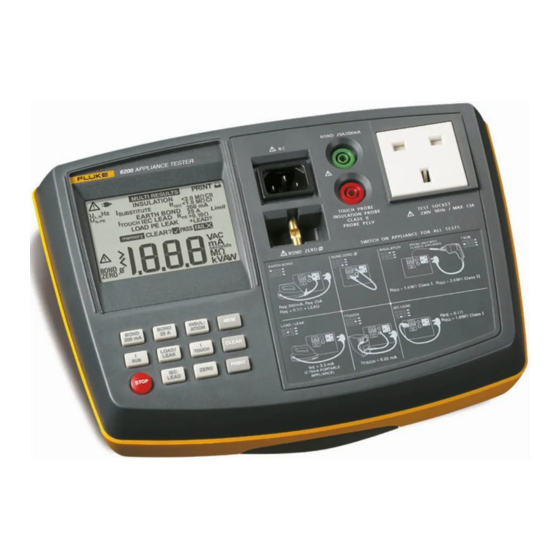
Page 10: Operating Features
Earthed bar to zero the Earth Bond test lead. shown and listed below. Socket to connect IEC lead for IEC Lead test . Serial RS-232 Port to connect the Fluke printer. Socket to connect test lead and crocodile clip for BOND 25A/200mA 6200 APPLIANCE TESTER Earth Bond test. -
Page 11: Understanding The Pushbuttons
Users Manual Operating Features Understanding the Pushbuttons Understanding the Beeper Sounds Use the pushbuttons to control operation of the tester. The tester can make several types of beeper sounds. Sound Meaning Button Function BOND Click A button is pressed. Start the 200 mA Earth Bond test. 200mA 1 beep A test passed. -
Page 12: Understanding The Display
6200 Users Manual Understanding the Display PRINT MULTI RESULTS INSULATION <2.0 M CII <1.0 M CI SUBSTITUTE N-PE 200 mA EARTH BOND 25 A Limit IEC LEAD TOUCH > 0.10 LOAD PE LEAK +LEAD? memory seconds kVAW Figure 2. Display Features... - Page 13 Please check the mains polarity. MULTI RESULTS Multiple test results will be displayed in succession. PRINT Printing results. Fluke SP1000 mini printer is connected. INSULATION Insulation test. <2.0 MΩ CII Lights up if the recommended insulation resistance (R ) limit is exceeded <1.0 MΩ...
- Page 14 6200 Users Manual Annunciator Meaning When a value is outside of the limit, the symbol FAIL X is displayed. When the limit is met, the symbol PASS is displayed. PASS FAIL A single test has passed or failed. Readings and measurement units field, error message field. >...
-
Page 15: Powering The Tester
The adjacent table shows the messages that can be shown when you power up the tester. The values are memory > Memory nearly full (>75%). examples and can differ from the displayed values. + number Tester failure, contact Fluke support. -
Page 16: Setting Up The Tester
+ number Dangerous tester failure. Unplug the earth bond test. tester, prevent it from being used, and contact Fluke for repair. Zeroing the Earth Bond Test The Neutral-Earth voltage is For correct earth bond test results you must zero the N-PE dangerously high. - Page 17 Users Manual Setting Up the Tester The tester saves the zero value so you will not need to repeat the operation every time you use the tester. If the Earth Bond test has been zeroed, the idle screen and subsequent earth bond test results will be marked ∅...
-
Page 18: Testing Appliances
6200 Users Manual insulation test (in this sequence) prior to any Testing Appliances other test. If any of these tests fail further testing Testing Safely must be stopped and any faults must be rectified. Warnings • During the load/leakage test and the touch •... -
Page 19: Continuous Test Mode
Users Manual Testing Appliances To enable you to test these appliances you can skip Continuous Test Mode the Fuse/L-N Loop Pre-test. To perform the test on To start a continuous non-live test hold down the test appliances that fail the Fuse/L-N Loop Pre-test do the button for at least 2 seconds. -
Page 20: Saving The Test Results
6200 Users Manual Saving the Test Results Bond Test 25 A / 200 mA (R To save the result after completing a test, do the The test checks the resistance between the earth pin of following: the appliance cable plug and the exposed metalwork on the appliance. - Page 21 Users Manual Testing Appliances BOND Start the 200 mA test or the 25 A test: 200mA Single test - press momentarily BOND Continuous test - hold down > 2 seconds The display shows the test progress, see the table below. During the measurement flex the flexible cord along its length to help find any broken conductors or poor quality joints.
-
Page 22: Insulation Test (Riso)
6200 Users Manual Note Insulation Test (R The insulation test may be not suitable for some types of Warning appliances. For these appliances an alternative test may be conducted such as a touch current, leakage current, • The test voltage is 500V dc. Do not touch the or suitable leakage current test. -
Page 23: Substitute Leakage Current Test (Isubstitute)
Users Manual Testing Appliances Substitute Leakage Current Test (I SUBSTITUTE The test measures the leakage current between • the earth pin of the appliance cable plug (Class I) • the test probe attached to the appliance under test (Class II). and the Live and Neutral pins of the appliance (pins are connected together within the tester for this test). - Page 24 6200 Users Manual Start the test: DISPLAY EXPLANATION Single test - press momentarily The substitute leakage current test has SUBSTITUTE been selected. Continuous test - hold down > 2 seconds The display shows the test progress, see the seconds The test time is counted down. table below.
-
Page 25: Touch Current Test (Itouch)
Users Manual Testing Appliances To perform the Touch Current test, do the following: Touch Current Test (I TOUCH Connect the appliance and the test probe as Warning indicated on the tester, see also Figure 7. NEVER carry out this test unless you have first For Class II appliances apply the probe to carried out a thorough visual inspection, any exposed metalwork on the appliance. - Page 26 6200 Users Manual DISPLAY EXPLANATION FAIL X The Fuse/L-N Loop pre-test tailed. Check that the appliance power switch is on. See also Fuse/L-N Loop Pre-test below. Figure 7. Touch Current Connections DISPLAY EXPLANATION The touch current test has been TOUCH selected.
-
Page 27: Load/ Leakage Current Test
Users Manual Testing Appliances Fuse/L-N Loop Pre-test Load/ Leakage Current Test The pre-test verifies the fuse and lead continuity by Warning applying a low voltage signal across the appliances phase and neutral pins. NEVER carry out this test unless you have first carried out a thorough visual inspection, Very low power appliances, or appliances with followed by a test of the earthing (Class I... - Page 28 6200 Users Manual To perform the Load/PE Leakage test do the following: Connect the appliance and the test lead as indicated on the tester, see also Figure 8. LOAD/ Start the test: LEAK Single test - hold down the button and release it after the second beep, before you hear a third long beep.
- Page 29 Users Manual Testing Appliances Fuse/L-N Loop Pre-test LOAD The load current is 0.2 A. The pre-test verifies the fuse and lead continuity by > Load current overrange detected. applying a low voltage signal across the appliances The load power is 50 VA. phase and neutral pins.
-
Page 30: Iec Lead Test
6200 Users Manual IEC Lead Test The IEC lead test tests the IEC lead for: • Earth bond resistance • Insulation resistance Live-Neutral against earth. • Live-Neutral lead/fuse continuity and polarity. If there is a swapped polarity condition and a continuity failure in the same test, a failed polarity message will be displayed. - Page 31 Users Manual Testing Appliances DISPLAY EXPLANATION FAIL X Test failed IEC LEAD The IEC LEAD test has been selected. L-N broken or open seconds The test time is counted down. L-N short circuit MULTI RESULTS The test is finished. The results are L-N are swapped.
-
Page 32: Pelv Test
6200 Users Manual PELV Test Using the Memory The PELV (Protective Extra Low Voltage) test measures The tester has a non-volatile memory to save a minimum the voltage on the PROBE PELV input when the idle of 100 test results. The power-on screen shows a screen is being displayed.. -
Page 33: Saving Test Results
Users Manual Using the Memory Saving Test Results Clearing the Store The clear function clears all memory locations. It is Warning disabled when any appliance test is running. In continuous test mode the test continues Print the results before clearing the store if you want to whilst you are saving the result! preserve the results. -
Page 34: Printing Test Results
The print function prints all the stored results from the In this case also the idle screen will not show the icon. earliest to the latest using the optional Fluke SP1000 mini printer. Printing is disabled when any appliance test is If printing fails, do the following: running. -
Page 35: Maintaining The Tester
Dirt or moisture on the earth bond test lead plug can Users Manual (this manual) result in a contact resistance that affects the readings. Therefore periodically zero the earth bond test (see page Can be downloaded from your regional Fluke website, 10). start at www.fluke.com . Calibration Table 3. -
Page 36: Specifications
6200 Users Manual Operating Altitude ........0 up to 2000 m Specifications Sealing..... IP-40 (enclosure), IP-20 (connectors) General Specifications Size..... 200 mm (L) x 275 mm (W) x 100 mm (H) EMC......complies with EN61326-1, criteria B Weight............... 3.0 kg EMI Immunity.............3 V/m Power Supply.... -
Page 37: Test Specifications
Users Manual Specifications Accuracy (after Bond Test zeroing) ..± ( 5% + 4 counts) Test Specifications Display Range ..........0 to 19.99 Ω The accuracy specification for the display range is Resolution ..............0.01 Ω defined as ± (%reading + digit counts) at 23 °C ± 5 °C, ≤... -
Page 38: Substitute Leakage Current Test (Isub)
6200 Users Manual Load/ Leakage Test: Load Current Substitute Leakage Current Test (I Display Range ............0 to 13 A Operational Error Measurement Range ... 0.25 to 19.00 mA Accuracy ..........± (4% + 2 counts) Operational Error ............10% Resolution..............0.1 A Accuracy .......... -
Page 39: Test Limits For Pass Result
Users Manual Specifications IEC Lead Test: IEC Lead Test ................ < 0.10 Ω Earth bond, limit ............0.10 Ω ................. > 2 MΩ Test current .............10 A ac Insulation resistance, limit ........2.0 MΩ Test voltage............500 V DC Fuse test and polarity check Variation Factor Errors Variation Designation...
Need help?
Do you have a question about the 6200 and is the answer not in the manual?
Questions and answers