
Subscribe to Our Youtube Channel
Related Manuals for Fluke 7102


Summary of Contents for Fluke 7102
- Page 1 7102 Micro-Bath User’s Guide 2013 Rev. 1, 2/22 © 2013-2022 Fluke Corporation. All rights reserved. Specifications are subject to change without notice.
- Page 2 Fluke authorized resellers shall extend this warranty on new and unused products to end-user customers only but have no authority to extend a greater or different warranty on behalf of Fluke. Warranty support is available only if product is purchased through a Fluke authorized sales outlet or Buyer has paid the applicable international price.
-
Page 3: Table Of Contents
Table of Contents Title Page Introduction....................Safety Information ..................Contact Fluke Calibration ................Service Information..................Specifications .................... Environmental Conditions................Quick Start....................Unpacking....................Bath Environment ................. Bath Fluids (Summary) ................. Installation ....................Power ......................Thermal Electric Devices................Set the Temperature.................. Bath Use.................... - Page 4 7102 User’s Guide Fluid Lifetime ..................15 Safety ....................16 Cost ...................... 16 Commonly Used Fluids................. 16 Mineral Oil..................16 Silicone Oil (Dow Corning 200.05, 200.10, 200.20)......16 Fluid Characteristics Charts..............17 Limitations and Disclaimer ..............18 About the Graph................. 19 Stirring .......................
- Page 5 Micro-Bath Stabilization and Accuracy ................ 34 Calibration ....................34 Calibration Points ..................34 Calibration Procedure................35 Compute DELTA................... 35 Compute R0 & ALPHA ................. 36 Accuracy and Repeatability ..............36 Maintenance ....................36 Troubleshooting Problems, Possible Causes, and Solutions ....37...
- Page 6 7102 User’s Guide...
-
Page 7: Introduction
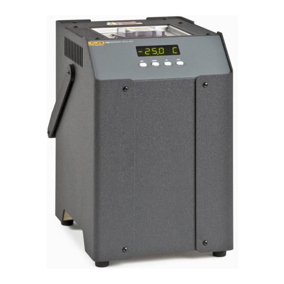
Introduction The Fluke Calibration 7102 Micro-Bath (the Product, calibrator, or instrument) is a portable instrument/ bench-top temperature calibrator. Use the Product to calibrate thermocouple and RTD temperature probes. The Product is small enough to use in the field, and accurate enough to use in the lab. With an ambient temperature of 23 °C (74 °F), calibrate over a range of −5 °C to 125 °C (23 °F to 257 °F). -
Page 8: Safety Information
7102 User’s Guide Safety Information General Safety Information is in the printed Safety Information document that shipped with the Product. It can also be found online at www.Flukecal.com. More specific safety information is listed in this manual where applicable. A Warning identifies conditions and procedures that are dangerous to the user. A Caution identifies conditions and procedures that can cause damage to the Product or the device under test (DUT). -
Page 9: Contact Fluke Calibration
• Fluke Calibration does not recommend the use of water as a fluid in the Product. If the tank coating is compromised, galvanic corrosion will occur due to dissimilar metals and the presence of water (electrolyte). -
Page 10: Specifications
7102 User’s Guide Specifications Table 1. Specifications −5 °C to 125 °C (23 °F to 257 °F) Range Accuracy ±0.25 °C ±0.015 °C at −5 °C (oil, 5010) Stability ±0.03 °C at 121 °C (oil, 5010) Uniformity ±0.02 °C 0.01 °C/F... -
Page 11: Environmental Conditions
Unpack the Product carefully and inspect it for any damage that may have occurred during shipment. If there is shipping damage, notify the carrier immediately. Verify that these components are present: • 7102 Micro-Bath • 7102/7103 Safety Information • Transport/Pour Access Lid • Probe Basket •... -
Page 12: Bath Fluids (Summary)
Bath Fluids (Summary) The Product does not come with fluid. Various fluids are available from Fluke Calibration and other sources. To safely operate the Product, only select bath fluids with adequate thermal properties that meet the application requirements. -
Page 13: Power
Micro-Bath Power 5. Power on the Product. Toggle the switch on the power entry module (PEM), see Figure 2. The fan blows air through the Product and the display illuminates after 3 seconds. After a brief self test, the Product begins normal operation. If the Product fails to operate, check the power connection. 6. -
Page 14: Set The Temperature
7102 User’s Guide Set the Temperature Temperature Set-point explains how to set the calibrator temperature set-point with the front panel keys. Briefly, the procedure is: 1. Push SET twice to access the set-point value. 2. Push UP or DOWN to change the set-point value. -
Page 15: Parts And Controls
Parts and Controls This section describes the bath and its parts. Front Panel This section describes and shows the front panel. See Figure 1. Figure 1. 7102 Front Panel 7102 MICRO-BATH –5°C to 125°C EXIT DOWN Controller Display (A) – The digital display not only shows set and actual temperatures but also shows various calibrator functions, settings, and constants. -
Page 16: Back Panel
7102 User’s Guide Back Panel This section describes and shows the back panel. See Figure 2. Figure 2. 7102 Back Panel DISPLAY HOLD RS-232 Power Cord – Underneath the calibrator is the removable power cord inlet that plugs into an IEC grounded socket (A). -
Page 17: Accessories
Micro-Bath Accessories Accessories Transport/Pour Access Lid Use the provided transport/pour access lid (see Table 2) to keep the fluid in the bath when transporting. Table 2. Bath Lids and Lid Parts Item Description Item Description Pour Spout Transport/Pour Access Lid Pour Spout Cover Optional Access Cover Transport Plug... -
Page 18: Access Cover (Optional)
7102 User’s Guide Access Cover (Optional) An aluminum access cover (see Table 2) is available for optimum stability. Drill holes into the access cover to insert the probes into the well. The holes must be within the guide ring for the probes to fit into the probe basket. -
Page 19: Stir Bar
Nevertheless, make sure to insert probes to the same depth in the bath liquid. Be sure that all probes are inserted deep enough to prevent stem effect. Fluke Calibration recommends a general rule for immersion depth to reduce the stem effect to a minimum: 20 x the diameter of the DUT + the sensor length. -
Page 20: Calibration Of Multiple Probes
7102 User’s Guide For best results when you calibrate over a wide temperature range, start at the lowest temperature and progress to the highest temperature. Use probe clamps or drill holes in the access cover to hold probes in place. Other fixtures to hold the probes can be designed. -
Page 21: Viscosity
Micro-Bath General Operation Viscosity Viscosity is the thickness measurement of a fluid and how easily it can be poured and mixed. Viscosity affects the temperature stability of the bath. Fluid mixing is better with low viscosity and this creates a more uniform temperature throughout the bath. -
Page 22: Safety
At lower temperatures, mineral oil is quite viscous, and control can be poor. At higher temperatures, vapor emission is significant. The vapors can be dangerous, and Fluke Calibration highly recommends a fume hood. As with most oils, mineral oil expands as temperature increases so do not fill the bath so full that it overflows when heated. -
Page 23: Fluid Characteristics Charts
The charts include information on a variety of fluids which are often used as heat transfer fluid in baths. Because of the temperature range, some fluids may not be useful with your bath. Table 3. Table of Various Bath Fluids Fluid Lower Upper Thermal Thermal Resistivity (# = Fluke Tempera- Flash Viscosity Specific Specific Heat Temperature Conductivity Expansion... -
Page 24: Limitations And Disclaimer
Specifications may change and sources sometimes offer differing information. Fluke Calibration is not liable for any personal injury or damage to equipment, product, or facilities that result from the use of these fluids. The user of the bath is responsible and must collect correct information, exercise proper judgment, and ensure safe operation. -
Page 25: About The Graph
Micro-Bath Stirring About the Graph The fluid graph illustrates some of the important qualities of the fluids shown. Temperature Range: The temperature scale in the graph is in degrees Celsius. The fluids’ general range of application is indicated by the shaded bands. Qualities that include pour point, freeze point, important viscosity points, flash point, boiling point, and others may be shown. -
Page 26: Fluid Drain
Temperature Controller A Fluke Calibration unique hybrid digital/analog temperature controller controls the bath temperature. The controller offers the tight control stability of an analog temperature controller as well as the flexibility and programmability of a digital controller. -
Page 27: Well Temperature
Micro-Bath Well Temperature Well Temperature The display allows direct viewing of the actual well temperature. This temperature value is what is normally shown on the display. The temperature units are displayed at the right. For example, 100.00C Well temperature in degrees Celsius Push Exit to access the temperature display function from any function. - Page 28 7102 User’s Guide Figure 6. Controller Operation Flowchart Display Hold Temperature Display Temperature DOWN DOWN Select Setpoint Displays Set-Point Resistance Adjust Setpoint Toggles °C / °F EXIT EXIT Units °C/°F Secondary Functions EXIT Scan On/Off Menu EXIT Display Power Scan Rate Set Proportional Band Adj.
-
Page 29: Temperature Scale Units
Micro-Bath Scan Temperature Scale Units The selected units (Celsius (°C) or Fahrenheit (°F)) show in the displayed well temperature, set-point, and proportional band. Push SET after you adjust the set-point value to change display units. Un= C Scale units currently selected Push UP or DOWN to change the units. -
Page 30: Scan Rate
7102 User’s Guide Scan Rate The next function in the main menu is the scan rate. Set the scan rate from .1 °C/min to 99.9 °C/min. The maximum scan rate, however, is limited by the natural heating or cooling rate of the instrument. -
Page 31: Mode Setting
Micro-Bath Temperature Display Hold Mode Setting The hold function is always in the automatic mode. In this mode the normal position is set to whatever the switch position is when the set-point is changed. For example, if the switch is currently open when the set-point is changed, the closed position then becomes the new active position. -
Page 32: Secondary Menu
7102 User’s Guide Secondary Menu Access less-used functions with the secondary menu. To access the secondary menu, push SET and EXIT simultaneously, then release. The first function in the secondary menu is the heater power display. (See Figure 6.) Thermal Electric Device (TED) The temperature controller controls the temperature of the well by pulsing the TED on and off. -
Page 33: Controller Configuration
Micro-Bath Controller Configuration The proportional band width is easily adjusted from the front panel. Set the width to discrete values in degrees C or F, which depends on the selected units. The proportional band adjustment is accessed within the secondary menu. Push SET and EXIT to enter the secondary menu and show the heater power. -
Page 34: Stir Speed
7102 User’s Guide Stir Speed The Stir Speed parameter adjusts stirrer motor speed. The factory default is 20. Str SP Flashes Str Sp and then displays the setting Current stir speed setting To change the stir speed, push UP or DOWN. -
Page 35: Duplex Mode
Micro-Bath Controller Configuration Duplex Mode The next parameter is the duplex mode. The duplex mode can be set to full duplex or half duplex. With full duplex, any commands received by the calibrator with the serial interface will be immediately echoed or transmitted back to the device of origin. -
Page 36: Alpha
7102 User’s Guide This probe parameter refers to the resistance of the control probe at 0 °C (32 °F). The value of this parameter is set at the factory for best instrument accuracy. ALPHA This probe parameter refers to the average sensitivity of the probe between 0 °C (32 °F) and 100 °C (212 °F). -
Page 37: Serial Communications
Micro-Bath Serial Communications Serial Communications The calibrator has an RS-232 serial interface that allows serial digital communications over fairly long distances. Use a serial interface to access any of the functions, parameters, and settings discussed in except for the BAUD rate setting. Wiring The serial communications cable attaches to the calibrator through the DB-9 connector at the back of the instrument. - Page 38 7102 User’s Guide Table 5. Controller Communications Commands Command Returned Acceptable Command Description Command Format Returned Example Example Values Display Temperature set: Read current set-point s[etpoint] set: 999.99 {C or F} 150.00 C Instrument Set current set-point to n s[etpoint]=n s=200.00...
-
Page 39: Calibrate A Single Probe
Set CG calibration *cg=n *cg=-4.115 parameter Functions not on menu Read firmware version *ver[sion] *ver ver.9999,9.99 ver.7102,2.00 number Read structure of all h[elp] list of commands commands Read all operating list of parameters parameters Legend: [] Optional Command data... -
Page 40: Stabilization And Accuracy
7102 User’s Guide Stabilization and Accuracy The stabilization time of the bath depends on the conditions and temperatures involved. Typically, the test well will be stable to 0.1 °C within 10 minutes of reaching the set-point temperature. Ultimate stability is achieved 30 minutes after the bath reaches the set temperature. -
Page 41: Calibration Procedure
Micro-Bath Calibration Procedure Calibration Procedure Follow these steps for the calibration procedure: 1. Choose three set-points to use in the calibration of the R0, ALPHA, and DELTA parameters. These set-points are generally 2.5 °C, 45 °C, and 100.0 °C (36.5 °F, 113 °F, and 212 °F) but other set- points can be used. -
Page 42: Compute R0 & Alpha
7102 User’s Guide Compute R0 & ALPHA − delta − delta Where: delta is the new value of DELTA computed above Program the new values for DELTA (delta), R0 (rzero), and ALPHA (alpha) into the Product with these steps. -
Page 43: Troubleshooting Problems, Possible Causes, And Solutions
Product. If there are any questions, see Service Information. • Before the use of any cleaning or decontamination method except those recommended by Fluke Calibration, check with an Authorized Service Center to be sure that the proposed method does not damage the Product. - Page 44 7102 User’s Guide Problem Possible Causes and Solutions Incorrect scan and scan rate settings. The scan and scan rate settings may be set to unwanted values. Check the Scan and Scan The Product heats or cools too quickly or too Rate settings.
- Page 45 Micro-Bath Troubleshooting Problems, Possible Causes, and Solutions Problem Possible Causes and Solutions Possible RF energy emission. With the unit stable, slowly rotate the unit. If no change occurs, the unit may need to be calibrated. If the display changes more than twice the normal display deviation, another unit in the area could be emitting RF energy.
- Page 46 7102 User’s Guide...
Need help?
Do you have a question about the 7102 and is the answer not in the manual?
Questions and answers