Table of Contents
Advertisement
Quick Links
Via Acquanera, 29
22100 Como
tel. 031.526.566 (r.a.) fax 031.507.984
info@calpower.it
www.calpower.it
PN 3499335
September 2009 Rev. 1, 6/10
© 2009-2010 Fluke Corporation. All rights reserved. Printed in UK. Specifications are subject to change without notice.
All product names are trademarks of their respective companies.
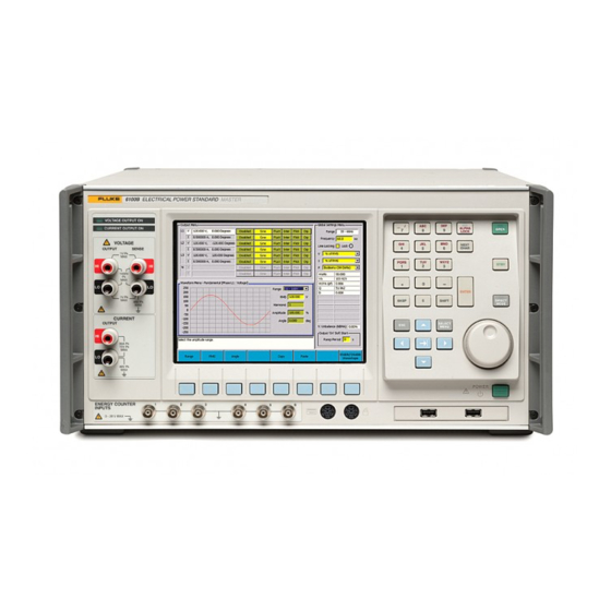
6100B/6105A
Electrical Power Standards
Users Manual
Advertisement
Table of Contents

Subscribe to Our Youtube Channel
Related Manuals for Fluke 6100B


Summary of Contents for Fluke 6100B
- Page 1 6100B/6105A Electrical Power Standards Users Manual PN 3499335 September 2009 Rev. 1, 6/10 © 2009-2010 Fluke Corporation. All rights reserved. Printed in UK. Specifications are subject to change without notice. All product names are trademarks of their respective companies.
- Page 2 Fluke’s warranty obligation is limited, at Fluke’s option, to refund of the purchase price, free of charge repair, or replacement of a defective product which is returned to a Fluke authorized service center within the warranty period.
-
Page 3: Table Of Contents
Table of Contents Chapter Title Page Introduction ..................1-1 1-1. Introduction................... 1-3 1-2. Contacting Fluke................... 1-3 1-3. General Safety Summary ..............1-3 1-4. Explanation of Safety-Related Symbols and Terms......1-4 1-5. Protective Earth (Grounding) ............1-4 1-6. Features....................1-5 1-7. - Page 4 6105A and 6106A Sinusoidal Power Accuracy at 45 Hz to 65 Hz; Power Factor 0.5 (ppm) ..........1-19 1-48. 6100B and 6101B Sinusoidal Power Accuracy at 45 Hz to 65 Hz; Power Factor 1.0 (ppm) ..........1-20 1-49. 6100B and 6101B Sinusoidal Power Accuracy at 45 Hz to 65 Hz;...
- Page 5 Setting up Voltage and Current Waveforms ......... 4-12 4-26. Harmonics, DC and Sine ..............4-13 4-27. Definition..................4-13 4-28. Access to Edit Harmonics ..............4-13 4-29. 6100B Capability................4-13 4-30. Sine/Harmonic Mode................ 4-13 4-31. Setting up Harmonics and DC ............4-15 4-32. Grid Edit Mode................. 4-16 4-33.
- Page 6 6100B/6105A Users Manual 4-41. 6100B Capability................4-19 4-42. Setting Up Fluctuating Harmonics ........... 4-19 4-43. Dips and Swells ..................4-20 4-44. Definition..................4-20 4-45. Access to Dips and Swells..............4-20 4-46. 6100B Capability................4-21 4-47. Setting Up Dips/Swells..............4-21 4-48.
- Page 7 Contents (continued) 5-16. Instrument STATUS Subsystem ............5-9 5-17. Incoming Commands and Queries ........... 5-10 5-18. Instrument Functions and Facilities..........5-10 5-19. Outgoing Responses ................. 5-10 5-20. Query Error..................5-10 5-21. Request Service (RQS)..............5-11 5-22. Reasons for Requesting Service........... 5-11 5-23.
- Page 8 6100B/6105A Users Manual 5-71. Interharmonics Phenomenon............5-46 5-72. Dip Phenomenon................5-47 5-73. Flicker Phenomenon..............5-48 5-74. Status Subsystem Command Details ..........5-49 5-75. System Subsystem Command Details ..........5-51 5-76. Unit Subsystem Command Details........... 5-52 5-77. Remote Operation of the Energy option ..........5-53 5-78.
- Page 9 The Effect of Phase Uncertainty on Power Accuracy ...... 7-5 7-11. Calibration Uncertainties for Full Accuracy......... 7-6 7-12. Required Equipment ................7-6 7-13. Overview of 6100B Signal Generation..........7-7 7-14. Independence of 6100B and 6101B............7-7 7-15. The Fluke Service Center Calibration System........7-9 7-16.
- Page 10 6100B/6105A Users Manual Appendices A Glossary....................... A-1 viii...
- Page 11 List of Tables Table Title Page 1-1. Symbols........................1-4 2-1. Line Cords by Country................... 2-4 3-1. Front-Panel Features ....................3-4 3-2. Rear-Panel Features ....................3-16 4-1. Waveshape Parameters................... 4-22 4-2. Basic Flicker Function ................... 4-24 4-3. Periodic Frequency Changes.................. 4-26 4-4.
- Page 12 6100B/6105A Users Manual...
- Page 13 Figure Title Page 2-1. Auxiliary Unit Connectors on the 6105A Rear Panel ..........2-5 3-1. 6100B Front Panel....................3-3 3-2. Graphical User Interface ..................3-6 3-3. The Output Menu (L1 Voltage Selected) ............... 3-9 3-4. The Output Menu (L1 Current Selected) ............... 3-10 3-5.
- Page 14 6100B/6105A Users Manual 4-23. Waveshape Softkeys ....................4-20 4-24. Waveform Menu for Dip..................4-20 4-25. Top Level Dip Softkeys ..................4-21 4-26. Dip Waveshape Softkeys ..................4-22 4-27. Dip Trigger Softkeys....................4-22 4-28. Flicker Softkeys ..................... 4-23 4-29. Basic Flicker Softkeys.................... 4-24 4-30.
- Page 15 Chapter 1 Introduction Title Page 1-1. Introduction..................... 1-3 1-2. Contacting Fluke..................1-3 1-3. General Safety Summary ................ 1-3 1-4. Explanation of Safety-Related Symbols and Terms......1-4 1-5. Protective Earth (Grounding) ............. 1-4 1-6. Features....................1-5 1-7. About this Manual .................. 1-5 1-8.
- Page 16 6105A and 6106A Sinusoidal Power Accuracy at 45 Hz to 65 Hz; Power Factor 0.5 (ppm) ..............1-19 1-48. 6100B and 6101B Sinusoidal Power Accuracy at 45 Hz to 65 Hz; Power Factor 1.0 (ppm) ..............1-20 1-49. 6100B and 6101B Sinusoidal Power Accuracy at 45 Hz to 65 Hz;...
-
Page 17: Introduction
Adding one to three 6101B or 6106A Auxiliary Instruments extends a system to up to four phases. For greater flexibility, the 6100B and 6105A Master units can also be configured as Auxiliaries by connecting one cable externally. The 6105A and 6106A are high-accuracy versions of the 6100B and 6101B respectively. -
Page 18: Explanation Of Safety-Related Symbols And Terms
Risk of danger. Important information. See manual. Earth ground. Conforms to relevant Canadian Standards Association directives. Conforms to relevant European Union directives. Do not dispose of this product as unsorted municipal waste. Go to Fluke’s website for recycling information. 1-5. Protective Earth (Grounding) Protection Class 1 - The Instrument must be operated with a protective earth/ground connection via the protective earth/grounding conductor of the ac line supply cable. -
Page 19: Features
Introduction Features XWWarning To avoid electrical shock or personal injury, do not intentionally or unintentionally interrupt the protective ground conductor inside or outside the Instrument. Interrupting the protective ground conductor is likely to make the Instrument dangerous. Intentional interruption is prohibited. 1-6. -
Page 20: Specifications
Max. Consumption 1000 VA max from 100 - 130 V, 1250 VA max from 130 V - 260 V Dimensions 1-11. 6100B, 6101B, 6105A, and 6106A With 50 A or 80 A Options Height 233 mm (9.17 inches) 324 mm (12.8 inches) Height (without feet) 219 mm (8.6 inches) -
Page 21: General Electrical Specifications
Introduction General Specifications 1-15. General Electrical Specifications Voltage/Current amplitude setting resolution 6 digits Range of fundamental frequencies 16 Hz - 850 Hz Line frequency locking 45 Hz - 65.9 Hz at user’s discretion Frequency accuracy ±50 ppm Frequency setting resolution 0.1 Hz Warm up time to full accuracy 1 hour or twice the time since last warmed up... -
Page 22: Electrical Specifications
Users Manual 1-18. Electrical Specifications The accuracies stated include the calibration uncertainty provided by Fluke Service Centers. In the following specifications, uncertainty is stated at coverage factor k = 2, equivalent to 96 % confidence level, in accordance with accepted metrology practices. -
Page 23: Voltage Sine Amplitude Specifications
Introduction Electrical Specifications Voltage Sine Amplitude Specifications 1-22. 6100B & 6101B 1- 6105A & 6106A 1- 6100B, 6101B, 6105A & Year Accuracy, Year Accuracy, tcal 6106A Open Loop 24- ±5 °C ± Ranges Frequency Voltage tcal ±5 °C ± (ppm of Hour Stability ±... -
Page 24: Voltage Dc And Harmonic Amplitude Specifications
6100B/6105A Users Manual Voltage DC and Harmonic Amplitude Specifications 1-23. 6105A & 6106A 6100B & 6101B Open Loop 24- Hour Stability ± 1-Year Accuracy, 1-Year Accuracy, tcal [4][5] Range Output Frequency ±5 °C ±(ppm ±5 °C ±(ppm of (ppm of output +... -
Page 25: Voltage Distortion And Noise
Introduction Electrical Specifications 1-24. Voltage Distortion and Noise Non-harmonic Noise Maximum Harmonic Distortion Range and Frequency Floor (relative to full Either: range) the largest of or the largest of 16 Hz - 4 MHz Full Frequency Range Volts % Setting % Range 480 μV 16 Hz - 850 Hz... -
Page 26: Load Regulation Specification "Adder
20 × Example: The output is a 800 Hz, 0.5 A rms sine wave on the 5 A range. The 6100B current specification from “Current Sine Amplitude Specifications” is: 139 ppm + 120 μA = 70 μA + 120 μA The voltage across the output is 6 V peak and maximum compliance is 14 V, for example, V >... - Page 27 Introduction Electrical Specifications 6100B & 6101B 6105A & 6106A Open Loop Current 1-Year Accuracy, 24-Hour Stability Range 1-Year Accuracy, Frequency ±(ppm of output ±5 °C ±(ppm of (Amps) (Amps) ±5 °C ±(ppm of tcal tcal [1][2] + μA) output + μA) output + μA)
-
Page 28: Current Dc And Harmonic Amplitude Specifications
6100B/6105A Users Manual Current DC and Harmonic Amplitude Specifications 1-28. 6105A & 6106A 6100B & 6101B Open Loop 1-Year Accuracy, 1-Year Accuracy, 24-Hour Stability Range Current Frequency ±(ppm of output ±5 °C ±(ppm ±5 °C ±(ppm tcal tcal [1][2] + μA) of output + μA) -
Page 29: Current Distortion And Noise
Harmonic phase angle significantly affects the peak value of a non-sinusoidal waveform. For a load less than specified, calculate error from parallel combination of source and load impedance. Sine Specifications 1-32. 6100B & 6101B 1- 6105A & 6106A 1- Open Loop 24- Year Accuracy, Hour Stability ±... -
Page 30: Dc And Harmonic Amplitude Specifications
6100B/6105A Users Manual DC and Harmonic Amplitude Specifications 1-33. 6100B & 6101B 6105A & 6106A 1-Year Open Loop Stability 1-Year Accuracy, tcal [4][5] ±5 °C ± ± (ppm of output + Range Output Frequency Accuracy, tcal ±5 °C ± (ppm of output [2][3] (ppm of output + μV) -
Page 31: Current To Voltage Phase Specifications
Current to Voltage Phase Specifications 1-35. For Voltage from the Current terminals, use the 0.25 A to 21 A phase specification. 6105A /6106A Voltage and 6100B / 6101B Voltage and Voltage or Current For All Voltage Ranges Current Components >40 % of Current Components >40 %... -
Page 32: Multi-Phase Operation
Multi-Phase Operation 1-36. 1-37. Voltage to Voltage Phase Specifications For All Voltage 6105A /6106A Voltage and 6100B / 6101B Voltage and Voltage or Current Ranges Current Components >40 % Current Components >40 % Component 0.5 % - 40 % of... -
Page 33: Accuracy
450 Hz. They are not valid when any of: Flicker, Fluctuating harmonics, Dip/Swell or Interharmonics are applied to the voltage or current channel of that 6100B. 1-46. 6105A and 6106A Sinusoidal Power Accuracy at 45 Hz to 65 Hz; Power Factor 1.0 (ppm) -
Page 34: 6105A And 6106A Sinusoidal Power Accuracy With
6100B/6105A Users Manual 6100B and 6101B Sinusoidal Power Accuracy at 45 Hz to 65 Hz; Power 1-48. Factor 1.0 (ppm) Power with Current at 90 % of Range Power with Current at 50 % of Range Current 23 V to 360 V 23 V to 360 V 1008 V Range;... -
Page 35: Voltage And Current Sinusoidal And Rectangular Modulation Flicker Specification
Introduction Electrical Specifications Voltage and Current Sinusoidal and Rectangular Modulation Flicker 1-52. Specification ±30 % of set value within range values (60 % ΔV/V) Setting range Flicker modulation depth accuracy 0.025 % Modulation depth setting resolution 0.001 % Shape of modulation envelope Rectangular, Square or Sinusoidal 0.01 % to 99.99 %;... -
Page 36: Interharmonic Specifications
Frequency range of interharmonic 16 Hz to 9 kHz Dip/Swell Specifications 1-55. Although Dips and Swells are primarily voltage phenomena, the 6100B provides the same facility on its current output. TTL falling edge remaining low for 10 μs Trigger-in requirement... -
Page 37: Non-Sinusoidal Voltage Example
The waveform is a 60 Hz, 110 V rms waveform, from the 168 V range, comprising 10 % 95 harmonic, 30 % 3 harmonic with the remainder contributed by the fundamental frequency. Using the 6100B voltage uncertainty values in “Voltage and Sine Amplitude Specifications” and “Voltage DC and Harmonic Specifications”, determine the 1-year accuracy. -
Page 38: Apparent Power Example
“Voltage and Sine Amplitude Specifications” and “Voltage DC and Harmonic Specifications”, current uncertainty values are given in “Current Sine Amplitude Specifications” and “Current DC and Harmonic Amplitude Specifications”. The accuracy used is that of the 6100B. 02727 The voltage rms value is Accuracy contribution from the voltage fundamental: 112 ppm of 109 V + 4.4 mV = (109x0.000112) + 0.0044 = 0.012208 + 0.0044 = 0.016608 V... -
Page 39: Power (P) Accuracy Calculations
Specifications”, current uncertainty values are given in “Current Sine Amplitude Specifications” and “Current DC and Harmonic Amplitude Specifications”. Phase uncertainty values are given in “Current to Voltage Phase Specifications”. The accuracy used is that of the 6100B. Converting all values to ppm, accuracy contribution at the fundamental frequency ×... - Page 40 Reactive Power (Q) but no single definition has been agreed. The difficulty is that Q is used for a number of different calculations including transmission line efficiency and voltage line drop. The 6100B allows users to select the definition that best meets their needs. The following methods are supported:...
-
Page 41: References
Introduction Electrical Specifications 1-62. References 6100B reactive power calculations are guided by the published work of Dr. Stefan Svensson: Svensson, S., (1999), Power Measurement Techniques for Nonsinusoidal Conditions, Chalmers Other pertinent papers are: Budeanu, C., (1927), "Reactive and fictitious powers", Rumanian National Institute, No.2. - Page 42 6100B/6105A Users Manual 1-28...
-
Page 43: Installation
Chapter 2 Installation Title Page 2-1. Introduction..................... 2-3 2-2. Unpack and Inspection................2-3 2-3. To Reship the Instrument................ 2-3 2-4. Placement....................2-3 2-5. Cooling Considerations................2-3 2-6. Line Voltage ................... 2-4 2-7. Connect to Line Power ................2-4 2-8. Connect Auxiliary Units ................. 2-5 2-9. - Page 44 6100B/6105A Users Manual...
-
Page 45: Introduction
A packing list is included in the packaging. When you unpack the Instrument, check for all the standard equipment listed and check the shipping order for any additional items ordered. Report any shortage to the place of purchase or to the nearest Fluke Service Center. -
Page 46: Line Voltage
If a supply lead is provided WITHOUT a mains connector, please observe the following color coding when wiring up your own mains connector - line = brown, neutral = blue, earth = green/yellow. Table 2-1. Line Cords by Country Country Fluke Line Cord Part Number 1998167 Europe 1998171 Australia, New Zealand, China... -
Page 47: Connect Auxiliary Units
6101B and 6106A have one Auxiliary Control Input. The older 6101A can also be added as Auxiliary units to 6100B and 6105A Master units. When upgraded to firmware issue 4.10 or greater the older 6100A Master can control any of 6105A, 6106A, 6100B, and 6101B as Auxiliary units. -
Page 48: Allocation Of Phases
L2 Control Output becomes L2 etc. See the Users Manual for an overview of instrument control and the user interface. This section is a reference for the functions and locations of the 6100B front and rear panel features, and provides brief descriptions of each feature for quick access. -
Page 49: Features
Chapter 3 Features Title Page 3-1. Introduction..................... 3-3 3-2. Front-Panel Features ................3-3 3-3. The Main User Interface Areas............... 3-6 3-4. Data Entry from the Front Panel ............3-7 3-5. Direct/Indirect Mode ................3-8 3-6. Using an External Keyboard and Mouse..........3-8 3-7. - Page 50 6100B/6105A Users Manual...
-
Page 51: Introduction
SENSE 1V Pk PQRS WXYZ STBY 1430V ENTER 1V Pk DIRECT BKSP SHIFT 46V Pk MODE CURRENT OUTPUT SELECT MENU 30A Pk 15V Pk 46V Pk ENERGY COUNTER INPUTS 0 - 28 V MAX gdw03.eps Figure 3-1. 6100B Front Panel... - Page 52 - In Direct Mode, the key LED is lit and all waveform changes take immediate effect. When Direct Mode is not active, the 6100B is in Deferred mode. In Deferred mode changes to waveforms are stored but not applied. Stored changes can be applied simultaneously or undone.
- Page 53 Features Front-Panel Features Table 3-1. Front-Panel Features (cont.) Number Description - In text input mode (Alpha Lock LED lit), key text using a combination of and the Alphanumeric keypad (15). This operates much in the manner of a cell phone, allowing one alpha key to source more than one text character by being pushed repeatedly until the ...
-
Page 54: The Main User Interface Areas
6100B/6105A Users Manual 3-3. The Main User Interface Areas The user interface is divided into five areas. There are three Menu panes, a message window, and at the bottom, the context-sensitive softkey indicators. See Figure 3-2. gdw04.bmp Figure 3-2. Graphical User Interface The Menu fields are accessed sequentially clockwise by pushing . -
Page 55: Data Entry From The Front Panel
Features The Main User Interface Areas • Under the Waveform Menu is the Message Window which provides context-sensitive help and warning and error messages. The background of this area is white for help messages and orange for warnings. Warnings include messages indicating that invalid data has been entered or operating boundaries would be exceeded if a set up request were processed. -
Page 56: Direct/Indirect Mode
3-5. Direct/Indirect Mode Changes to 6100B settings will usually be made one at a time. Sometimes it is necessary to make a number of changes all at once. Consider a three phase system where all three voltage phases are set to 120 V. To change each phase voltage individually in sequence would cause the three phase system to become unbalanced. -
Page 57: Sample Reference Signal And F10
See Chapter 7. 3-8. Set Up Exercise A 6100B or 6105A is required to perform the following training exercise. The task is to set up the current channel to output 2.0 A. After following the power up instructions earlier in this manual, the L1 voltage channel (L1 V) output values are shown with a white background. -
Page 58: Switch To The Current Output
6100B/6105A Users Manual 3-9. Switch to the Current Output The focus must be on the current channel to set it up. After power up the Menu focus will be on the Waveform Menu (blue border). 1. Push (or F9) once to move the focus to the Output Menu. -
Page 59: The Current Channel Is Enabled But Not Operating
Features Set Up Exercise Push the Enable/Disable softkey and the L1 current row in the Output Menu shows as “Enabled”. See Figure 3-6. gdw09a.bmp Figure 3-6. The Output Menu (L1 Current Selected) 3-11. The Current Channel is Enabled but Not Operating There is not yet output at the Instrument output terminals. -
Page 60: Over-Compliance Warning Message
Simply put, the voltage is developed across a load is determined by OHMS law, i.e., V = I x Z. As the terminals are open, the output sees very high impedance which requires very high voltage. The 6100B 10 V limit is exceeded so the over compliance trips will be activated. -
Page 61: Turn The Output Off
The 6100B is provided with a four to two-wire lead set for voltage. Irrespective of two- wire / four-wire configuration, the four plugs at the 6100B end of the lead should always be plugged in when the lead is in use. -
Page 62: Four-Wire Sense
6100B/6105A Users Manual 3-16. Four-Wire Sense In two-wire sensing, the sense point for the control system feedback loop is at the back of the terminals. Any current flowing in the leads connecting the OUTPUT terminals to the load causes a volt drop in the leads. As a result, the voltage at the load is less than at the terminals and accuracy is compromised. - Page 63 Features Two-Wire / Four-Wire Voltage Settings gdw15a.bmp Figure 3-12. Front-Panel Configuration Softkeys Note that the softkeys have changed. Select two or four wire using the softkeys, or with and or the Scroll Wheel when the Voltage Binding Posts group has focus. Two wire is the initial default setting but the setting is non-volatile.
-
Page 64: Rear-Panel Features
Number Description Main Power On-Off Switch -This is a true mains isolating switch. Auxiliary Unit Control Connectors - Connection to Auxiliary units via Fluke supplied cable. Trigger Out Connector - The Trigger Output Connector has a +5 V CMOS logic drive providing a falling edge time marker intended to synchronize external equipment to the dip/swell function. - Page 65 20 MHz reference output signal derived from the system master clock. Blanked if the CLK option is not fitted. Auxiliary Control Input - Two Master units (6100B/6105A) can be connected together to act as Master and Auxiliary. For example, the interconnection cable would be plugged into the L2 Control output of the Master and into the Auxiliary Control Input of the unit delegated to be the Auxiliary.
- Page 66 6100B/6105A Users Manual 3-18...
-
Page 67: Front-Panel Operation
Setting up Voltage and Current Waveforms ........... 4-12 4-26. Harmonics, DC and Sine ................ 4-13 4-27. Definition.................... 4-13 4-28. Access to Edit Harmonics ..............4-13 4-29. 6100B Capability................4-13 4-30. Sine/Harmonic Mode................4-13 4-31. Setting up Harmonics and DC ............4-15 4-32. Grid Edit Mode................... 4-16 4-33. - Page 68 6100B/6105A Users Manual 4-39. Definition.................... 4-19 4-40. Access to Fluctuating Harmonics ............4-19 4-41. 6100B Capability................4-19 4-42. Setting Up Fluctuating Harmonics ............. 4-19 4-43. Dips and Swells ..................4-20 4-44. Definition.................... 4-20 4-45. Access to Dips and Swells..............4-20 4-46.
-
Page 69: Introduction
Front-Panel Operation Introduction 4-1. Introduction This chapter describes operating the 6100B from the front panel, including all aspects of setting up and configuring the Instrument. Before following the procedures in this chapter, familiarize yourself with the front-panel controls, displays, and terminals, which are identified and described in detail in Chapter 3. -
Page 70: Basic Setup Procedures
6100B/6105A Users Manual 4-4. Basic Setup Procedures Refer to Chapter 3 for an explanation of how to navigate though the user interface and how to set up text and numeric values. When the Instrument start-up sequence is complete, the instruments main setup page is displayed. See Figure 4-1. -
Page 71: Global Settings
Front-Panel Operation Global Settings 4-5. Global Settings Navigate to the Global Settings Menu using . See Figure 4-2. gdw33.bmp Figure 4-2. Global Menu Softkeys 4-6. Frequency Set the required output frequency. An attempt to set frequency outside the active band when any output is ON will cause a warning message to be displayed. -
Page 72: Reactive Calculations
6100B/6105A Users Manual Note An error message will be generated if the peak value of the waveform exceeds the range maximum. Changing the fundamental value alters all harmonics accordingly. • Harmonics entered as dB down value from the fundamental value This mode acts in the same way as % of fundamental. -
Page 73: Soft Start
Front-Panel Operation Global Settings 4-10. Soft Start The Soft Start feature reduces the likelihood of internal over-voltage/current-detector trips caused by inrush current. Inrush current occurs when a device connected to the voltage terminals takes its operating power from the Instrument voltage signal. As the power supply smoothing capacitors begin to charge very high, short duration peaks of current are taken from the Instrument. -
Page 74: Front-Panel Terminals
The Instrument is provided with a four to two wire lead set for voltage. Irrespective of two-wire / four-wire configuration the four plugs at the 6100B end of the lead should always be plugged in when the lead is in use. The sense wires will always... -
Page 75: Rear-Panel Output Settings
This pop up screen also controls the Reference Clock Output option (if fitted). The Reference Clock Out option provides a reference signal derived from the master processor clock frequency and may be used to synchronize systems to the 6100B. The reference may be switched between off, 10 MHz, and 20 MHz. -
Page 76: More Settings
6100B/6105A Users Manual 4-14. More Settings The More Settings softkey provides access to further functionality. See Figure 4-8. Pressing returns the softkeys to the top level. gdw44.bmp Figure 4-8. More Settings Softkeys 4-15. Voltage from Current Transfer Factors The current output of the Instrument can be configured to output a voltage representing a current from, for example, a current transformer with load resistor. -
Page 77: Set Date And Time
Front-Panel Operation Edit Mode Note 6100A setups are not transferrable to 6100B and 6105A and vice versa. 4-17. Set Date and Time Date and time are adjusted via the Date and Time softkey. 4-18. GPIB Settings Bus address, Event Status Enable (ESE), Status Register Enable (SRE) and Power On status Clear (PSC) can be configured with the GPIB Settings pop-up screen. -
Page 78: Setting Up Voltage And Current Waveforms
6100B/6105A Users Manual output is on) • Global settings Time/Date and GPIB settings cannot be changed in deferred mode • Load/Save setup is not available in deferred mode Note Entry into Calibration mode automatically selects Direct mode. 4-25. Setting up Voltage and Current Waveforms The following describes setting up voltage waveforms but applies equally to current. -
Page 79: Harmonics, Dc And Sine
The following sections explain the Harmonics, dc, and Sine Menus. 4-27. Definition A Harmonic is an integer multiple of the fundamental frequency. In the 6100B, harmonic number 1 is the fundamental frequency. DC is denoted by harmonic 0. 4-28. Access to Edit Harmonics Use ... - Page 80 6100B/6105A Users Manual Note that Figure 4-10 shows the L2 voltage channel in sine mode. Figures 4-12 and 4-13 show L1 voltage in Harmonics mode. gdw10.bmp Figure 4-12. Harmonics with Time Domain Graph 4-14...
-
Page 81: Setting Up Harmonics And Dc
Front-Panel Operation Harmonics, DC and Sine gdw11.bmp Figure 4-13. Harmonics with Frequency Domain Graph 4-31. Setting up Harmonics and DC If the Global Settings are set to "percentage of RMS value", the fundamental amplitude is automatically adjusted as harmonics are added, in order to maintain the RMS value constant. -
Page 82: Grid Edit Mode
6100B/6105A Users Manual To remove a single harmonic from the set-up, set its amplitude to 0 % or use the Remove Harmonic softkey. See Figure 4-15. gdw12.bmp Figure 4-15. Softkeys for Waveform Edit mode If harmonics are set up they are retained when harmonics are disabled by selecting Sine (Enable/Disable Waveshape). -
Page 83: Interharmonics
Front-Panel Operation Interharmonics gdw56.bmp Figure 4-16. Grid Edit Screen Use the Edit Voltage Channel or Edit Current Channel softkeys to choose or edit the voltage or current channel. Figure 4-17 shows the softkeys for editing the Voltage channel. gdw58.bmp Figure 4-17. Second-Level Grid Edit Mode Softkeys An external mouse and keyboard can be used to navigate around the grid and enter values for amplitude and phase angle. -
Page 84: Access To Edit Interharmonics
Use to navigate to the Waveform Menu and select the Edit Interharmonics softkey. See Figure 4-19. gdw60.bmp Figure 4-19. Waveform Menu for Interharmonics 4-36. 6100B Capability Maximum value of a single The maximum value for an interharmonic <2850 Hz is 30 % interharmonic of range. -
Page 85: Definition
Use to navigate to the Waveform Menu and select Edit Fluct Harmonics from the softkeys. See Figure 4-21. gdw15.bmp Figure 4-21. Waveform Menu for Fluctuating Harmonics 4-41. 6100B Capability Number of harmonics to fluctuate Any number from 0 to all set harmonics can fluctuate Modulation depth setting range... -
Page 86: Dips And Swells
Output Menu. 4-43. Dips and Swells Dips and swells are primarily a voltage phenomenon but are also provided for the 6100B current channel. An example of using dip in the current channel is to set up the "Burst Fired" waveform required by IEC 61036 and the 62053 series of standards. The following sections explain the Dips and Swells Menu. -
Page 87: 6100B Capability
Repetitions determines how many Dip/Swell events will occur when a trigger occurs in External Trigger (One Shot) mode. Copy and Paste allow transfer of the current settings to another 6100B phase. Use the Enable/Disable Waveshape softkey to turn Dip/Swell on or off. - Page 88 The dip/swell is triggered once by external trigger applied to the TRIGGER INPUT connector on the 6100B rear panel. The trigger signal must be TTL compatible. The low going transition causes a trigger starting the first number of Dips/Swells set in the Dip/Swell repetitions control.
-
Page 89: Flicker
An output trigger is provided to control external equipment. This trigger appears on the TRIGGER OUTPUT connector on the rear of any 6100B or 6101B producing a dip or swell. The output trigger may be set to occur at the same time as the input trigger (0 seconds delay), or delayed by a time set in the Trigger Output control field. -
Page 90: 6100B Capability
6100B/6105A Users Manual 4-51. 6100B Capability The implementation of Flicker is separated into two groups- Basic Functions and Extended Functions. The Basic Functions group allow the depth and frequency of rectangular and Sine to be chosen for calibration of Flickermeters at the settings in IEC 61000-4-15. -
Page 91: Setting Up Flicker Extended Functions
Front-Panel Operation Flicker gdw24.bmp Figure 4-31. Flicker Menu (Changes per Minute) can only be set by varying ΔV/V, Change Rate and P cannot be directly set. P inst and Waveform parameters, or by changing the channel voltage or frequency settings. Duty Cycle setting does not affect P value. -
Page 92: Periodic Frequency Changes
6100B/6105A Users Manual 4-54. Periodic Frequency Changes The Periodic Frequency Changes Flicker function, see Figure 4-33, provides a fixed pattern of changes every 4 seconds. Frequency is stepped ±0.25 Hz either side of the fundamental frequency while voltage steps by up to 1.2 V depending on voltage and fundamental frequency settings. -
Page 93: Distorted Voltage With Multiple Zero Crossings
Front-Panel Operation Flicker 4-55. Distorted Voltage with Multiple Zero Crossings The Distorted Voltage with Multiple Zero Crossings Flicker function, see Figure 4-34, output consists of the fundamental frequency plus 12 “odd” harmonics. The phase angle of the harmonics is 180 º. See Table 4-4 and Table 4-5. gdw28.bmp Figure 4-34. -
Page 94: Harmonics With Side Bands
6100B/6105A Users Manual 4-56. Harmonics with Side Bands The Harmonics with Side Bands Flicker function, see Figure 4-35, allows the input bandwidth of Flickermeters to be explored. The Fundamental frequency voltage waveform is modulated by two frequencies simultaneously. Both frequencies are of the same amplitude. -
Page 95: Rectangular Voltage Changes With 20 % Duty Cycle
Front-Panel Operation Flicker gdw30.bmp Figure 4-36. Phase Jumps Table 4-7. Phase Jumps Phase jump 120 V, 60 Hz 230 V, 50 Hz 120 V, 50 Hz 230 V, 60 Hz angle Δß ±30 º 0.587 0.913 0.706 0.760 ±45 º 0.681 1.060 0.819... -
Page 96: Copy And Paste
Instrument’s rear panel. 4-64. Principle of Operation One or more MUT are connected to the 6100B voltage and current terminals. A test is conducted which involves counting the number of pulses received within a specified period. The result is compared with the theoretical amount of energy delivered, or against a reference source that was connected in parallel to the MUT. -
Page 97: Limitations
Extremely non-linear loads such as the power supply of electronic meters disrupt the 6100B and 6101A ability to maintain the correct output state. Attempting to provide line power to energy meters from the 6100B system may cause the 6100B output to trip or result in inaccurate readings. - Page 98 6100B/6105A Users Manual Figure 4-39 shows the interface which overlays the Waveform menu. gdw36.bmp Figure 4-39. Energy Mode Each row of the display relates to a MUT channel. From left to right, the display shows the channel number, the instantaneous power indicated from that channel, the energy...
-
Page 99: Input Channel Configuration And Meter Constants
Front-Panel Operation Input Channel Configuration and Meter Constants 4-67. Input Channel Configuration and Meter Constants The system must first be configured to the required MUT and reference meter set-up. Push the Configure Meter Constants softkey to access the configuration options. See Figure 4-40. -
Page 100: Type Of Energy
Under normal operating conditions, all 6100B main outputs are turned off at the end of a test. If the MUT or reference meters are using the 6100B as a power source, they may lose their configuration if the voltage is removed from them between tests. If Maintain Voltage Signal On Completion is selected in Counted/Timed, Gated or Packet mode, the Current output(s) will turn off, but the Voltage output(s) will not. -
Page 101: Free Run Mode
The purpose of the Counted/Timed Mode is to allow measurements to be made when both the 6100B and MUT are fully stabilized after warm-up and the 6100B output has settled after the output is turned on. The minimum warm-up time is 2 seconds. See Figure 4-42. -
Page 102: Gated Mode
In the Counted/Timed mode, the MUT and reference meter dials may advance more than the amount measured by the 6100B Energy Option. This is normal, and represents settling and warm-up times included in the test. The actual test duration and count to achieve the displayed result is accurate. -
Page 103: Packet Mode
In the Gated mode, the MUT and reference meter dials may advance more than the amount measured by the 6100B Energy Option. This is because the dial will advance in the period before the gate signal becomes active. The count displayed by the 6100B accurately reports the pulses received during the time the gate is active. -
Page 104: Remote Operation Of The Energy Option
To start counting using the Energy Option, the energy-option status panel must be displayed on the 6100B, if another wave-shape definition panel is shown, only the power outputs will be activated, not the energy counter/timer. To guarantee correct operation it is recommended that a command from the “ENERgy”... -
Page 105: Remote Operation
Chapter 5 Remote Operation Title Page 5-1. Introduction..................... 5-5 5-2. Using the IEEE-488 Port for Remote Control ........5-5 5-3. Programming Options................5-5 5-4. Capability Codes..................5-5 5-5. Bus Addresses..................5-6 5-6. Limited Access ..................5-7 5-7. Interconnections..................5-7 5-8. Operation via the IEEE 488 Interface............. - Page 106 6100B/6105A Users Manual 5-39. The Error Queue................5-17 5-40. Instrument Status Reporting - SCPI Elements........5-17 5-41. General ....................5-17 5-42. SCPI Status Registers ................. 5-17 5-43. Reportable SCPI States............... 5-18 5-44. SCPI Programming Language..............5-18 5-45. SCPI Commands and Syntax ..............5-19 5-46.
- Page 107 Remote Operation Introduction 5-94. MUT Meter Constant ................. 5-58 5-95. MUT Meter Constant Units..............5-58 5-96. Input Debounce .................. 5-59 5-97. MUT Source ..................5-59 5-98. MUT Pull-up ..................5-59 5-99. Reference Tree ................... 5-59 5-100. Input Debounce .................. 5-59 5-101.
- Page 108 6100B/6105A Users Manual...
-
Page 109: Introduction
Digital Interface for Programmable Instrumentation”, and to IEEE 488.2 - 1988: “Codes, Formats, Protocols and Common Commands”. In IEEE 488.2 terminology the 6100B is a device containing a system interface. It can be connected to a system via its system bus and set into programmed communication with other bus-connected devices under the direction of a system controller. -
Page 110: Bus Addresses
The 6100B has one primary address, which can be set by the user to an exclusive value within the range from 0 to 30 inclusive. It cannot be made to respond to any address outside this range. -
Page 111: Limited Access
Remote Operation Limited Access 5-6. Limited Access The Instrument has three basic operating modes. Some of these modes only give limited support for remote control: • Manual Mode - Remote operation is available for all of manual mode, but for ease of programming, some remote commands do not mirror front panel operations exactly. -
Page 112: Programmed Transfer To Local Control (Gtl Or Ren False)
6100B/6105A Users Manual 5-11. Programmed Transfer to Local Control (GTL or REN False) The application program can switch the instrument into Local Control (by sending Command GTL, or by setting the REN line false), permitting a user to take manual control from the front panel. -
Page 113: Message Exchange
Remote Operation Message Exchange 5-14. Message Exchange 5-15. IEEE 488.2 Model IEEE 488.1 bus 9500 Bus 9500B Bus Transmissions Messages Transmissions IEEE-488-1 Filter out bus management and Bus Interface configuration commands Status Byte (STB) Input/Output Control RQS bit state for Status Byte General and Addressed Requested Bus Messages... -
Page 114: Incoming Commands And Queries
6100B/6105A Users Manual 5-17. Incoming Commands and Queries The Input Buffer is a first in, first out queue, which has a maximum capacity of 1024 bytes (characters). Each incoming character in the I/O Control generates an interrupt to the instrument processor, which places it in the Input Buffer for examination by the Parser. -
Page 115: Request Service (Rqs)
Remote Operation Retrieval of Device Status Information 5-21. Request Service (RQS) 5-22. Reasons for Requesting Service There are two main reasons for the application program to request service from the controller: • When the instrument’s message exchange interface is programmed to report a system programming error. -
Page 116: Ieee 488 And Scpi Standard Defined Features
6100B/6105A Users Manual 5-25. IEEE 488 and SCPI Standard Defined Features SCPI Status Structure Registers IEEE 488.2 Status Structure Registers Summary Bit — OSS Operation Status Operation Status Register Enable Register bit 15 bit 14 bit 13 bit 12 bit 11... -
Page 117: Event Register Conditions
The two SCPI Status registers operate in the same way, using the appropriate program commands to set the enable registers, and query commands to discover the condition of the registers (the 6100B does not make use of these registers). •... -
Page 118: Instrument Model Structure
OSR contains one or more enabled bits which are true, or false when all the enabled bits in the byte are false. The OSR is not used in the 6100B. 5-33. Reading the Status Byte Register The common query:*STB? reads the binary number in the Status Byte register. -
Page 119: Reading The Service Request Enable Register
Remote Operation Instrument Status Reporting IEEE 488.2 Basics originate an RQS. It contains a user modifiable image of the Status Byte, whereby each true bit acts to enable its corresponding bit in the Status Byte. The common program command:*SRE phs Nrf performs the selection, where Nrf is a decimal numeric, whose binary decode is the required bit pattern in the enabling byte. -
Page 120: Standard Event Status Enable Register
6100B/6105A Users Manual Note about the ERROR Queue The Error Queue is a sequential memory stack. Each reportable error has been given a listed number and explanatory message, which are entered into the error queue as the error occurs. The queue is read destructively as a First In/ First Out stack, using the query command SYSTem:ERRor? to obtain a code number and message. -
Page 121: Reading The Standard Event Enable Register
Remote Operation Instrument Status Reporting - SCPI Elements bits in the Standard defined Event Status Byte, those events which when true will set the ESB bit true in the Status Byte. It contains a user-modifiable image of the standard Event Status Byte, whereby each true bit acts to enable its corresponding bit in the standard Event Status Byte. -
Page 122: Reportable Scpi States
6100B/6105A Users Manual 5-43. Reportable SCPI States The 6100B does not normally use the Operation Status Event Register, but hardware,such as the energy counter/timer option does. 5-44. SCPI Programming Language. Standard Commands for Programmable Instruments (SCPI) is an instrument command language which goes beyond IEEE 488.2 to address a wide variety of instrument functions... -
Page 123: Scpi Commands And Syntax
Remote Operation SCPI Commands and Syntax 5-45. SCPI Commands and Syntax 5-46. SCPI Command Summary Keyword Parameter Form Notes CALibration :SECure :PASSword <spd> Used to enter calibration mode: Requires calibration password. :EXIT Used to exit calibration mode. :PHASe<x> <x> is phase (1 to 4): 1 is master phase. :VOLTage :RANGe <dnpd>, <dnpd>... - Page 124 6100B/6105A Users Manual Keyword Parameter Form Notes :CURRent :RANGe <dnpd>, <dnpd> Calibration range: <dnpd> = Low limit, High limit. :RANGe? [<cpd> {LOW | HIGH}] Calibration range query. :VOLTage <dpnd>, <dpnd> <dnpd> = low limit, high limit. :VOLTage(?) [<cpd>{ LOW | HIGH }] :UNIT? Response is VOLT (voltage) or CURR (current).
- Page 125 Remote Operation SCPI Commands and Syntax Keyword Parameter Form Notes INPut :DIP :TRIGger [No query form] [SOURce] :FREQuency(?) <dnpd> :LINE(?) <bool> {OFF | ON | 0 | 1} :LOCKed? :POWer :UNBalanced? Query only. :STANdard(?) [<cpd> { NEMA | IEC }] :BUDeanu? [<cpd>{DELTa|WYE}, <cpd>...
- Page 126 6100B/6105A Users Manual Keyword Parameter Form Notes :HARMonic<y> <dnpd>,<dnpd> <y> is harmonic number. <dnpd> = Amplitude, Phase. Note: amplitude absolute or % depending on value of UNIT:MHAR:... :AMPLitude(?) <dnpd> Absolute or % :PANGle(?) <dnpd> :HARMonic<y>? [<cpd> {AMPLitude | PANGle}] :ALL? [<cpd>...
- Page 127 Remote Operation SCPI Commands and Syntax Keyword Parameter Form Notes :SHAPe(?) <cpd> { RECTangular | SINusoidal | SQUare } :DUTY(?) <dnpd> :EFLicker [:STATe](?) <bool> { OFF | ON | 0 | 1 } :CONFigure(?) <cpd> { PF | MZ | HS | PJ | RV } :SPERiod(?) <cpd>...
- Page 128 6100B/6105A Users Manual Keyword Parameter Form Notes :AMPLitude(?) <dnpd> :PANGle(?) <dnpd> :HARMonic<y>? [<cpd>{ AMPLitude | PANGle ]} :ALL? [<cpd>{ AMPLitude | PANGle ]} Response is in CSV format. :FHARmonics [:STATe](?) <bool>{OFF|ON|0|1} :CLEar :FLUCtuate<y>(?) <bool>{OFF|ON|0|1} <y> is harmonic number. :ALL? Response in CSV format.
- Page 129 Remote Operation SCPI Commands and Syntax Keyword Parameter Form Notes RESults? <cpd> { CH1 | CH2 | CH3 | CH4 | CH5 | CH6 } Response = <dnpd>, power or frequency. <dnpd>, MUT Energy or counts. <dnpd>, Ref. Energy or counts. <dnpd>...
-
Page 130: Energy Command Summary
6100B/6105A Users Manual Keyword Parameter Form Notes :DIP :TIME(?) <cpd> {SEConds|CYCLes} :FLICker :CURRent(?) <cpd> {HZ | CPM} :VOLTage(?) <cpd> {HZ | CPM} 5-47. Energy Command Summary Keyword Parameter Form Notes [:SOURce] :ENERgy :MODE(?) <cpd>{ TCOunt | PACKet | GATE | FRUN }... -
Page 131: Calibration Subsystem Command Details
Before any adjustments can take place, access to calibration must be enabled. There is a switch (on the rear panel of the 6100B, marked CALIBRATION) that must be set to ENABLE. Having done this, the calibration password command must be sent. Once entered into calibration mode, only calibration commands are accepted;... - Page 132 6100B/6105A Users Manual Once a target has been set, the 6100B adjustment is restricted to values within the selected hardware voltage span, and frequency band. In order to release this restriction, one of the following commands must be sent: TRIG?, EXIT or a new TARG command.
-
Page 133: Output Subsystem Command Details
Remote Operation SCPI Commands and Syntax The response is: CURRent An ordinary current range is active. VOLTage A voltage out of current range is active. 5-49. Output Subsystem Command Details OUTPut[:STATe](?) <bool>{OFF|ON|0|1} This command turns the instrument’s output on or off, dependent upon the individual Voltage and Current channel output settings of each phase. - Page 134 6100B/6105A Users Manual Note Operations which are invalid when the output is ON are also invalid when Deferred mode is active, even if the output is OFF. For example you cannot change range in Deferred mode even if the output is OFF.
-
Page 135: Input Subsystem Command Details
Remote Operation SCPI Commands and Syntax 5-50. Input Subsystem Command Details INPut:DIP:TRIGger This command triggers all dip/swell phenomena that have external trigger selected. It has the same effect as supplying a trigger signal to the rear input External Trigger BNC. 5-51. -
Page 136: Power Values
6100B/6105A Users Manual The Current Binding posts selections apply only when the 50 A option is fitted. Currents up to 21A can be routed through the normal 4 mm binding posts or if preferred through the same terminals that provide the 50A output (lower terminals). The individual phases can be configured individually or all together. - Page 137 Remote Operation SCPI Commands and Syntax Example: 1.0E1,1.141E1,0.0E0,0.0E0 Note: P is identical to WATT. S is identical to VA. SOURce:PHASe<x>:POWer:FRYZe? [<cpd>{ P | S | Q }] This command is a query only. The default (no parameter) version will return all of the components from a calculation of the Phase’s Power according to Fryze in comma separated format, in the order P, S, Q.
-
Page 138: Voltage Setup
6100B/6105A Users Manual Example: 1.0E1,1.414E1,1.314E0,0.1E0 Note: P is identical to WATT. S is identical to VA. SOURce:PHASe<x>:POWer:IEEE? [<cpd>{ P | S | N | SN | P1 | S1 | Q1 | PH | SH | NH }] This command is a query only. The default (no parameter) version will return all of the components from a calculation of the Phase’s Power according to the IEEE Working Group... -
Page 139: Dc And Harmonics Phenomenon
Remote Operation SCPI Commands and Syntax For reference purposes, note that the following ranges are presently defined for the 6100B/6101B: Range Lower Limit Upper Limit 15 V range 0.0 V 23 V 30 V range 0.0 V 45 V 60 V range 0.0 V... - Page 140 6100B/6105A Users Manual The query command will return 1 if the harmonics are applied, or 0 if the harmonics are inactive. SOURce:PHASe<x>:VOLTage:MHARmonics:CLEar This command clears all harmonics, except the fundamental associated with this phase's voltage. It does not have a query form.
-
Page 141: Fluctuating Harmonics Phenomenon
Remote Operation SCPI Commands and Syntax Expected responses: :SOUR:PHAS:VOLT:HARM:ALL? "2.5E1,9.0E1,0.0E0,0.0E0,1.09E1,0 .0E0,0.0E0,0.0E0,2.5E0,1.65E2" :SOUR:PHAS:VOLT:HARM:ALL? "2.5E1,0.0E0,1.09E1,0.0E0,0.0E0,2 AMPL .5E0" :SOUR:PHAS:VOLT:HARM:ALL? "9.0E1,0.0E0,0.0E0,0.0E0,1.65E2" PANG 5-56. Fluctuating Harmonics Phenomenon SOURce:PHASe<x>:VOLTage:FHARmonics:STATe(?) <bool>{OFF|ON|0|1} This command turns the specified phase’s voltage channel fluctuating harmonics phenomena on and off. If no harmonics are currently selected for the specified phase, a suitable error message will be reported indicating that some harmonics need to be activated before fluctuation can be applied. -
Page 142: Interharmonics Phenomenon
6100B/6105A Users Manual This command selects the specified phase’s voltage channel fluctuating harmonics modulation shape: • RECT will set the modulation waveform to be rectangular. • SIN will set the modulation waveform to be sinusoidal. • SQU will set the modulation waveform to be square. -
Page 143: Flicker Phenomenon
Remote Operation SCPI Commands and Syntax SOURce:PHASe<x>:VOLTage:DIP:ENVelope? [<cpd>{CHANe | RIN | DURation | ROUT | EDELay}] The default version of this query returns the dip envelope settings for the specified phase's voltage channel. Add the appropriate optional parameter to return a single value: Change To value, expressed as a percentage of the total RMS Voltage CHANge the Ramp In period, expressed in Seconds or Cycles depending on the Dip... -
Page 144: Extended Flicker Sub-System
6100B/6105A Users Manual percentage of the total RMS voltage signal. The query version of this command will return the present modulation depth value. The returned number will be in standard scientific format (15.1 % would be returned as 1.51E1). SOURce:PHASe<x>:VOLTage:FLICker:FREQuency(?) <dnpd>... -
Page 145: Extended Flicker State
Remote Operation SCPI Commands and Syntax 5-61. Extended Flicker State [SOURce]:PHASe<x>:VOLTage:EFLicker[:STATe](?) <bool> { ON | OFF | 0 | 1 } Enable or disable the currently selected extended flicker signal configuration (for the passed phase x). If the output is on, the new configuration will be applied immediately to the output. 5-62. -
Page 146: Report Phase Jump Stage
6100B/6105A Users Manual • OFF- Apply no delay. • S5 - Delay by 5 Seconds. • S10 - Delay by 10 Seconds. • M1 - Delay by 1 Minute. • M5 - Delay by 5 Minutes. • M10 - Delay by 10 Minutes. - Page 147 Remote Operation SCPI Commands and Syntax Range Lower Limit Upper Limit 0.25 A range 0.05 A 0.25 A 0.5 A range 0. 05 A 0.5 A 1 A range 0.1 A 2 A range 0.2 A 5 A range 0.5 A 10 A range 10 A 21 A range...
-
Page 148: Harmonics Phenomenon
6100B/6105A Users Manual This selects whether the voltage out of current equivalence factor is applied. • ON or 1 will enable equivalence factor. • OFF or 0 will disable equivalence factor SOURce:PHASe<x>:CURRent:EQUivalence:FACTor(?) <dnpd> This command sets the value, in units of Volts per Amp, of the voltage to current equivalence factor SOURce:PHASe<x>:CURRent:TERMinal:ROUTe(?) <cpd>{ UPPer | LOWer }... -
Page 149: Fluctuating Harmonics Phenomenon
Remote Operation SCPI Commands and Syntax SOURce:PHASe<x>:CURRent:MHARmonics:HARMonic<y>:AMPLitude? This query returns the amplitude (in the presently selected Current amplitude Units of the specified harmonic on the specified phase. SOURce:PHASe<x>:CURRent:MHARmonics:HARMonic<y>:PANGle? This query returns the phase angle (in the presently selected phase angle units) of the specified harmonic on the specified phase. -
Page 150: Interharmonics Phenomenon
6100B/6105A Users Manual The query command will return 1 if the specified harmonic is being fluctuated, or 0 if the specified harmonic is not being fluctuated. SOURce:PHASe<x>:CURRent: FHARmonics:ALL? This query allows all the active harmonics to return their Fluctuation State as a comma delimited string. -
Page 151: Dip Phenomenon
Remote Operation SCPI Commands and Syntax AMPLitude | FREQuency}] The default version of this query returns all of the settings of the specified inter-harmonic, comma separated. Add the appropriate optional parameter to query just one of these values. 5-72. Dip Phenomenon SOURce:PHASe<x>:CURRent:DIP:STATe(?) <bool>{OFF|ON|0|1} This command turns the specified Phase’s Current channel Dip phenomena on and off. -
Page 152: Flicker Phenomenon
6100B/6105A Users Manual SOURce:PHASe<x>:CURRent:DIP:TRIGger:ODELay(?)<dnpd> This sets and queries the delay (in seconds or cycles) before the output trigger is generated, following the completion of a dip or swell. SOURce:PHASe<x>:CURRent:DIP:TRIGger:REPeat(?)<dnpd> This sets and queries the number of times a dip will repeat when in the external trigger mode. -
Page 153: Status Subsystem Command Details
Remote Operation SCPI Commands and Syntax SOURce:PHASe<x>:CURRent:FLICker:PST? This query only command will return the present PST value. The returned number will be in standard scientific format (1.82 would be returned as 1.82E0). SOURce:PHASe<x>:CURRent:FLICker:SHAPe(?) <cpd>{RECTangular|SINusoidal|SQUare} This command selects the specified phase’s current channel flicker modulation shape. •... - Page 154 Set back to 0 at the end of the test. STATus:QUEStionable [:EVENt]? Note The 6100B does not set any bits in this register. This command returns the contents of the Questionable Event register, clearing the register. STATus:QUEStionable:ENABle(?) <dnpd> This command sets the mask which enables those Questionable Event register bits which are required to be summarized at bit 3 of the IEEE 488.2 Status Byte register.
-
Page 155: System Subsystem Command Details
5-75. System Subsystem Command Details SYSTem:ERRor? As errors in the 6100B are detected, they are placed in a “first in, first out” queue, called the Error Queue. This queue conforms to the format described in the SCPI Command Reference (Volume 2), although errors only are detected. Three kinds of errors are reported in the Error Queue, in the sequence that they are detected: Command errors, execution errors and device-dependent errors. -
Page 156: Unit Subsystem Command Details
The Query will return the updated time at the moment the query was accepted as HH,MM,SS. SYSTem:VERSion? The query only command returns an <Nr2> formatted numeric value corresponding to the SCPI version number for which the 6100B complies. At the time of writing, this will be 1999.0. 5-76. Unit Subsystem Command Details UNIT:ANGLe(?) <cpd>{DEGrees|RADians} This command sets the units to be used to express all instances of Phase Angle. -
Page 157: Remote Operation Of The Energy Option
This is the default mode of operation. • PACKet Energy packet delivery mode. The power outputs are activated for the time it takes the 6100B to deliver a specific “packet” of energy and then deactivated again. • GATE Gated input mode. -
Page 158: Energy Units
6100B/6105A Users Manual The second parameter specifies whether all the enabled voltage channels should remain on after test completion. The default action is to turn off all enabled channels on test completion. The query form of the command also requires the mode parameter (i.e. MVOLtage? <cpd>). -
Page 159: Output Gating
Remote Operation SCPI Command Set commands, so data can be read a key stages in a test sequence. The following conditions can be monitored using the “STATus” system (see paragraph 51): • Warm up active. • Test active. • Input gate trigger pending. •... -
Page 160: Warm-Up Sequence Tree
6100B/6105A Users Manual • R1000 1 k Ohm. 5-86. Warm-up Sequence Tree The warm-up test sequence can be used to allow the MUT and reference sources to settle. A warm-up sequence can be configured in any operating mode, but will only have an effect when the operating mode is “TCOunt”. -
Page 161: Test Sequence Tree
Remote Operation SCPI Command Set • CH1 to CH6 Raw pulse streams from individual channels. • SUM456 Sum of channels 4 through 5. • MEAN456 Arithmetic mean of channels 4 through 6. • MEAN56 Arithmetic mean of channels 5 and 6. •... -
Page 162: Energy: Abort
6100B/6105A Users Manual Note: If one of the source parameters has been changed after using this command a valid default will be set (typically “MAIN”); so it is recommend that the “MUT:TEST:PSOUrce” command is sent after any “MUT:SOURce” or “REFerence:SOURce” commands, to prevent unexpected side effects. -
Page 163: Input Debounce
Remote Operation SCPI Command Set Note that there is no short form of these parameters. 5-96. Input Debounce ENERgy:MUT:DEBounce[:STATe](?) <bool> { ON|OFF|0|1 } The energy counter MUT inputs can be filtered to reduce switch contact bounce. The maximum usable pulse rate is 100 Hz when debounce is enabled. “ 5-97. -
Page 164: Reference Source
6100B/6105A Users Manual IPWH Impulses per Watt-hour IPKWH Impulses per killoWatt-hour IPKMH Impulses per MegaWatt-hour WHIP Watt-hour per impulse KWHIP killoWatt-hour per impulse KMHIP MegaWatt-hour per impulse Note that there is no short form of these parameters. 5-103. Reference Source ENERgy:REFerence:SOURce(?) { CH6|SUM456|MEAN456|MEAN56|MMUT|MAIN } This command specifies the pulse source(s) used to define the reference source. -
Page 165: Output Meter Constant Units
Remote Operation Common Commands and Queries 5-107. Output Meter Constant Units ENERgy:OUTPut:CONStant:UNIT(?){ IPWH|IPKWH| IPMWH|WHPI|KWHPI|MWHPI } This command specifies the meter constant units (as impulses per unit energy) used by channels considered to be MUT sources. IPWH Impulses per Watt-hour IPKWH Impulses per killoWatt-hour IPKMH Impulses per MegaWatt-hour... -
Page 166: Recall Event Status Enable
6100B/6105A Users Manual the status byte. Nrf is a Decimal Numeric Data Element representing an integer decimal value equivalent to the Hex value required to enable the appropriate bits in this 8 bit register. The detailed definition is contained in the IEEE 488.2 standard document. Note that numbers will be rounded to an integer. -
Page 167: Idn? (Instrument Identification)
*IDN? will recall the instrument’s manufacturer, model number, serial number and firmware level. Response Format: Character position Fluke,6100B,XXXXXXXXXXXX,X.XX or Fluke,6105A,XXXXXXXXXXXX,X.XX Where: The data contained in the response consists of four comma-separated fields, the last two of which are instrument-dependent. The data element type is defined in the IEEE 488.2 standard specification. -
Page 168: Recall The Instrument Hardware Fitment
Bit 6 50 A current option has been fitted. • Bit 7 Unused For example, a 6100B and a 6101B, the latter having 80A and bandwidth option would report “ 0,0,0,3,0,0,0,0”. Execution Errors: None. Power On and Reset Conditions Not applicable. -
Page 169: Power-On Status Clear
Remote Operation Common Commands and Queries 5-118. Power-On Status Clear This common command conforms to the IEEE 488.2 standard requirements. Figure 5-11. Power On Status Clear *PSC sets the flag controlling the clearing of defined registers at Power On. Nrf is a decimal numeric value which, when rounded to an integer value of zero, sets the power on clear flag false. -
Page 170: Reset
6100B/6105A Users Manual Execution Errors: None Power On and Reset Conditions No change. This data is saved in non-volatile memory at power off, for use at power on. 5-120. Reset Figure 5-13. Reset *RST will reset the instrument to a defined condition, stated for each applicable command with the command's description, and listed in “Device Settings at Power On”. -
Page 171: Recall Service Request Enable
Remote Operation Common Commands and Queries 5-122. Recall Service Request Enable This Status Byte data structure conforms to the IEEE 488.2 standard requirements for this structure. Figure 5-15. Service Request Enable Query *SRE? recalls the enable mask for the standard defined events. Response Decode: The value returned, when converted to base 2 (binary), identifies the enabled bits that will generate a service request. -
Page 172: Test Operations - Full Selftest
6100B/6105A Users Manual 5-124. Test Operations — Full Selftest This query conforms to the IEEE 488.2 standard requirements. Figure 5-17. Test Query *TST? executes a Full selftest. A response is generated after the test is completed. N. B. Operational selftest is valid only at temperatures: 23 °C ±10 °C. -
Page 173: Device Settings After *Rst
Remote Operation Device Settings After *RST 5-126. Device Settings After *RST *RST will reset the instrument to a defined condition, stated for each applicable command. The reset condition is not dependent on past use history of the instrument except as noted below: *RST does not affect the following: •... -
Page 174: Device Settings At Power On
6100B/6105A Users Manual 5-127. Device Settings at POWER ON 5-128. General Active Mode: The instrument powers up in “manual” mode. Device I/D (Serial Number). Factory serial number preserved. Status Reporting Conditions: Status Byte Register. Depends on state of *PSC. Status Byte Enable Register. -
Page 175: Rst Settings Related To Common Ieee 488.2 Commands
Remote Operation Device Settings at POWER ON 5-130. *RST Settings Related to Common IEEE 488.2 Commands Program Coding Condition *CLS Not applicable *ESE Nrf Not applicable *ESE? Previous state preserved *ESR? Previous state preserved *IDN? No Change *OPC OPIC state forced *OPC? OPIQ state forced *OPT? -
Page 176: Rst Settings Related To Scpi Commands
6100B/6105A Users Manual 5-131. *RST Settings Related to SCPI Commands Setting Value Following *RST OUTPut :STATe ROSCillator :STATe :SENSe Last set manually :DEFer :STATe :OUTPut :RAMP Unchanged :TIME Unchanged :RCLock :VOLTage :NLIMit Unchanged SOURce :FREQuency Last set manually :LINE :UNBalanced... - Page 177 Remote Operation Device Settings at POWER ON Setting Value Following *RST :FHARmonics :STATe :FLUCtuate<y> Harmonic 1 – 100 OFF :MODulation Depth 0.0% Frequency 10.0 Hz :SHAPe SINusoidal :IHARmonics :STATe :SIGNal<y> State Amplitude 0.0% Frequency 33 Hz :DIP :STATe :ENVelope Change to 10.0% Ramp In 0.0001 seconds...
- Page 178 6100B/6105A Users Manual Setting Value Following *RST :PJUMp :SPERiod(?) “OFF” :ANGLe(?) 30.0 :CURRent :STATe :RANGe 0.1 1 :VOLTage :EQUivalence STATe Unchanged FACTor Unchanged :AMPLitude :UNIT? CURR :MHARmonics [:STATe](?) :HARMonic<y> Harmonic 1 100% Harmonic 2 – 100 0% :FHARmonics :STATe :FLUCtuate<y>...
- Page 179 Remote Operation Device Settings at POWER ON Setting Value Following *RST Period 0.001 seconds Ramp Out 0.0001 seconds End Delay 0.0 seconds TRIGger: INPut: FREE HOLDoff: DEL, 0.0 ODELay: :FLICker :STATe :FREQuency 13.5 Hz :DEPTh 0.402 :SHAPe SQUare :TERMinal Unchanged :UNIT :ANGLe Last set manually...
-
Page 180: Energy Option Action On Receiving *Rst
6100B/6105A Users Manual 5-132. Energy Option Action on Receiving *RST The following default settings are used on receiving a *RST command. Setting Value Following *RST [:SOURce] :ENERgy :MODE(?) Timed/counted mode. :UNIT(?) Real (Wh). :OGATe(?) Output gate Off. Gate type level. -
Page 181: Worked Examples
Remote Operation Worked Examples 5-133. Worked Examples Examples summary: • Example 1 Create a pure ac voltage signal. • Example 2 Create an ac voltage signal with 2 harmonic destortion. • Example 3 Create an ac voltage signal with fluctuating 2 harmonic destortion. - Page 182 6100B/6105A Users Manual Set amplitude (in absolute units). SOUR:PHAS1:VOLT:MHAR:HARM2 10,0 Setup the fundamental frequency. SOUR:FREQ 60 Enable voltage output on this phase. SOUR:PHAS1:VOLT:STAT ON Set output to on (all phases). OUTP:STAT ON Example 3. Fluctuate the 2 Harmonic with a 25 Hz, sine wave at 30 % amplitude.
- Page 183 Remote Operation Worked Examples Setup frequency. SOUR:FREQ 60 Setup phase 1 (master) voltage range. SOUR:PHAS1:VOLT:RANG 0,180 Set amplitude (in absolute units). SOUR:PHAS1:VOLT:MHAR:HARM1 110,0 Set amplitudes and phases of harm 3. SOUR:PHAS1:VOLT:MHAR:HARM3 10,0 Set amplitudes and phases of harm 5. SOUR:PHAS1:VOLT:MHAR:HARM5 5,90 Enable main harmonics.
- Page 184 Example 9. Configure a master unit to output a pure 5V dc signal. Note that as dc is treated by the 6100B as the 0 harmonic of a fundamental frequency, that frequency must be defined even when as in this case, the fundamental has zero amplitude.
-
Page 185: Worked Examples
Remote Operation Worked Examples Example 10. Configure a master unit to output an AC signal of 60 Hz, 10 V RMS, with a 5 V dc offset, containing no aberrations. Reset all parameters to a known state. *RST Use % rms mode to easily calculate offset. UNIT:MHAR:VOLT PRMS Setup Phase 1 (master) voltage range. - Page 186 6100B/6105A Users Manual 5-82...
-
Page 187: Operator Maintenance
Chapter 6 Operator Maintenance Title Page 6-1. Introduction..................... 6-3 6-2. Confidence Test ..................6-3 6-3. Setting Up and Running the Confidence Test......... 6-3 6-4. Changing the User Password ..............6-4 6-5. Accessing the Fuse.................. 6-4 6-6. How to Clean the Instrument ..............6-5 6-7. - Page 188 6100B/6105A Users Manual...
-
Page 189: Introduction
6-2. Confidence Test The Confidence Test provides an indication that instrument performance has not deteriorated significantly. The test for connected Auxiliary units is run from the 6100B Master instrument. The test is not designed to be used to determine service intervals as the measurements made are relatively crude compared with those that would be made at routine calibration and adjustment. -
Page 190: Changing The User Password
Figure 6-1. Waveform Menu Top Level Softkeys Select Support Functions, Diagnostic Tools, and enter the user password. The default password when the 6100B is first shipped is “12321”. Select Change Password to display the “change the calibration password...” pop-up menu. Enter the existing password, the new password and the new password again. Push ... -
Page 191: How To Clean The Instrument
Operator Maintenance How to Clean the Instrument gdw033.eps Figure 6-2. Rear Panel Showing Fuse 6-6. How to Clean the Instrument Clean the exterior of the instrument using a soft cloth slightly dampened with either water or a non-abrasive mild cleaning solution that is not harmful to plastics. W Caution Do not use aromatic hydrocarbons or chlorinated solvents for cleaning. - Page 192 6100B/6105A Users Manual To clean the air filter proceed as follows. See Figure 6-3: 1. Disconnect line power. 2. The air filter is accessible from the rear of the unit. If the unit is sited on a bench, ensure that there is 24-inch clearance at the rear of the unit to allow you to withdraw the filter.
-
Page 193: Lithium Battery Replacement
Do not mix with the solid waste stream. Spent batteries should be disposed of by a qualified recycler or hazardous materials handler. Contact your authorized Fluke Service Center for recycling information. W Caution Do not leave batteries unused for extended periods of time, either in the product or in storage. - Page 194 6100B/6105A Users Manual...
-
Page 195: Calibration
The Effect of Phase Uncertainty on Power Accuracy ......7-5 7-11. Calibration Uncertainties for Full Accuracy........... 7-6 7-12. Required Equipment ................7-6 7-13. Overview of 6100B Signal Generation........... 7-7 7-14. Independence of 6100B and 6101B............7-7 7-15. The Fluke Service Center Calibration System........7-9 7-16. - Page 196 6100B/6105A Users Manual...
-
Page 197: Introduction
If the Instrument is used mainly at power line frequencies there are a number of commercially-available measuring power reference standards with accuracies comparable to that of the 6100B and 6105A. These can be used to perform a confidence check of 6100B accuracy. A single-phase device is sufficient to check both single and poly-phase 6100B systems. -
Page 198: Best Calibration Accuracy
7-8. Amplitude Measurements Rigorous type testing of the 6100B has shown that when the phase and gain of each voltage or current channel are correctly adjusted, all other specifications will be met. Consequently, calibration of 6100B/6105A can be achieved with sinusoidal signals. -
Page 199: The Effect Of Phase Uncertainty On Power Accuracy
Calibration Best Calibration Accuracy Note Zero-detection phase meters may give erroneous results in the presence of even harmonics because even harmonics can cause the zero crossing of a composite waveform to differ from the notional fundamental frequency zero crossing. Sampling techniques, on the other hand, can give phase uncertainties as low as 0.0008 degrees and are not susceptible to other harmonics affecting the measurement. -
Page 200: Calibration Uncertainties For Full Accuracy
0.195 ° 7-12. Required Equipment Two lists of equipment are provided for two different methods of calibrating the 6100B. Fluke’s method is used within the Fluke Service Centers and has measurement uncertainties which support the full specifications of the 6100B. -
Page 201: Overview Of 6100B Signal Generation
An overview of the 6100B signal generation system will aid further discussion of the Fluke method of calibration. An Electrical Power Standard system consists of a 6100B to provide a single phase of voltage and current, plus up to three 6101B auxiliaries. The voltage and current channels are independent of each other for amplitude but are linked by a common internal “Phase... - Page 202 6100B/6105A Users Manual A digital representation of the requested output waveform is sampled, converted to an analog signal and amplified. The D to A conversion process and subsequent amplification introduces a phase shift and the output at the binding posts lags the digitally generated waveform.
-
Page 203: The Fluke Service Center Calibration System
The digitizing DMM is triggered externally by a signal from the 6100B. The trigger signal, the Sample Reference, has a fixed phase relationship with the system Master Phase and controls that start of the sample period. - Page 204 Figure 7-3. Phase Measurement Connections Figure 7-3 shows how the 6100B, a digitizing DMM and transducer are connected. Note that voltage dividers and shunts are used to scale the input to the DMM for optimum performance. The same DMM is used to calibrate voltage and current.
- Page 205 Calibration The Fluke Service Center Calibration System The Sample Reference and the Phase Reference signals are provided on the 6100B rear panel. Figure 7-4 shows the relationship between reference signals and the analog output. The Sample reference is turned OFF and ON with GPIB commands. Sample Reference pulses do not appear after an ON command until the positive zero crossing of the Phase Reference occurs.
-
Page 206: Characteristics Of The Calibration System
Users Manual 7-16. Characteristics of the Calibration System Transducers are used to convert the different 6100B output voltage and current levels to nominally 800 mV. The DMM, a Fluke HP3458A/HFL with extended memory option, is used on its 1.2 V dc range for all measurements to reduce the relative phase uncertainty contribution from the DMM, i.e., errors in the DMM are the same for voltage and current. -
Page 207: Dmm Amplitude Phase Contributions
Table 7-7 above. 7-21. Current to Voltage Phase Uncertainty The phase of the current output of a 6100B or 6101B is specified relative to the voltage channel of the same instrument. By using the same DMM to measure both voltage and current against the common Sample Reference signal means all DMM related uncertainties other than short-term stability and measurement noise cancel. -
Page 208: Calibration Adjustment Process
Figure 7-5. Waveform Top Level 7-24. Entering Calibration Mode To make calibration adjustments, the 6100B (or 6101B) calibration switch must be in the Enable position. See Figure 3-9 and Table 3-2. Use the Password Prompt to enter your password. See Figure 7-6. -
Page 209: Determine The 6100B Error
7-26. Determine the 6100B Error Ensure the measurement equipment is correctly configured; connections are correctly made and turn the 6100B/6101B output on. After allowing the 6100B/6101B and measurement equipment time to settle, for each of the components to be adjusted: 1. -
Page 210: Verification
6100B/6105A Users Manual 7-29. Verification Verify adjustments using the same equipment against the product specification in Chapter 1. 7-30. Calibration Adjustment Points The following tables list the calibration adjustment points. Table 7-8. Voltage Adjustment Points Fundamental Output Level Output Phase... - Page 211 Calibration Calibration Adjustment Points Table 7-9. Current Adjustment Points Output Fundamental Output Phase Range Harmonic Frequency Level Frequency Point Angle Setting (Amps) Number (Hz) Setting (Hz) (Degrees) (Amps) 0.000 offset Gain 0.225 0.25 Gain 0.225 3024 Gain 0.200 5985 Gain 0.125 0.000 offset...
- Page 212 6100B/6105A Users Manual Output Fundamental Output Phase Range Harmonic Frequency Level Frequency Point Angle Setting (Amps) Number (Hz) Setting (Hz) (Degrees) (Amps) 0.000 offset Gain 18.000 Gain 18.000 Gain 18.000 1539 Gain 16.000 3024 Gain 16.000 4347 Gain 10.000 5040 Gain 10.000...
-
Page 213: Energy Option Calibration
The Use Internal Pull-up check box should be enabled (checked) for most frequency meters. For example, Enable and set the 6100B Voltage and Current to Sine 10 V rms and 1 A rms, phase angle zero, providing 10 W rms of real power. -
Page 214: Using An External Reference Frequency
6100B/6105A Users Manual 7-33. Using an External Reference Frequency Equipment required: a pulse source with frequency accuracy 2.5 ppm or better. 1. Connect any Pulse Input channel to an accurate frequency reference source between 10 Hz and 5 MHz. The source must be suitable to drive the Pulse Inputs. See Chapter 1 for input driving specifications. - Page 215 Equipment Under Test First harmonic The first harmonic of a waveform is its fundamental frequency. Note that for the 6100B, the 1st harmonic of a waveform may have zero amplitude. Flicker Repetitive (voltage) level variation in the range to cause the physiological phenomenon of flicker.
- Page 216 6100B/6105A Users Manual IEC 61868 Evaluation of Flicker severity IEC 61000-3-2 Limits for harmonic current emissions (equipment input current <= 16A per phase IEC 61000-3-3 Limits of voltage changes, voltage fluctuations and flicker in public low-voltage supply systems (for equipment <= 16A per...
- Page 217 Appendix A Glossary Reference voltage The reference voltage is the voltage that is used for determining the depth of a dip and the height of a swell. RMS voltage shape The time function of the RMS voltage change evaluated as a single value for each successive half period between zero- crossings of the source voltage.
- Page 218 6100B/6105A Users Manual Via Acquanera, 29 22100 Como tel. 031.526.566 (r.a.) fax 031.507.984 info@calpower.it www.calpower.it...
Need help?
Do you have a question about the 6100B and is the answer not in the manual?
Questions and answers