Table of Contents
Advertisement
Quick Links
Advertisement
Table of Contents

Related Manuals for HT HT7051


Summary of Contents for HT HT7051
- Page 1 ENGLISH User manual Copyright HT ITALIA 2021 Release EN 3.01 - 26/11/2021...
-
Page 2: Table Of Contents
HT7051 - HT7051N TABLE OF CONTENTS PRECAUTIONS AND SAFETY MEASURES ..............2 1.1 Preliminary instructions ......................2 1.2 During use ..........................3 1.3 After use ..........................3 1.4 Definition of measurement (overvoltage) category ............... 3 GENERAL DESCRIPTION ....................4 ... -
Page 3: Precautions And Safety Measures
HT7051 - HT7051N 1 PRECAUTIONS AND SAFETY MEASURES The instrument has been designed in compliance with standards IEC/EN61557-1 and IEC/EN61010-1 regarding electronic measuring instruments. CAUTION For the operator’s safety and to prevent damaging the instrument, follow the procedures described in this manual and carefully read all notes preceded by... -
Page 4: During Use
HT7051 - HT7051N 1.2 DURING USE Carefully read the following recommendations and instructions: CAUTION Failure to observe the cautions and/or instructions may damage the instrument and/or its components or generate a danger for the operator. If, during use, the low battery symbol appears on the display, insert the supply cable into the Europlug socket to start battery recharge. -
Page 5: General Description
HT7051 - HT7051N 2 GENERAL DESCRIPTION The instrument You purchased, if used in compliance with the indications given in this manual, guarantees accurate and reliable measurements and the utmost safety thanks to a development of new conception which ensures double insulation and, consequently, compliance with the requirements of overvoltage category IV. -
Page 6: Nomenclature
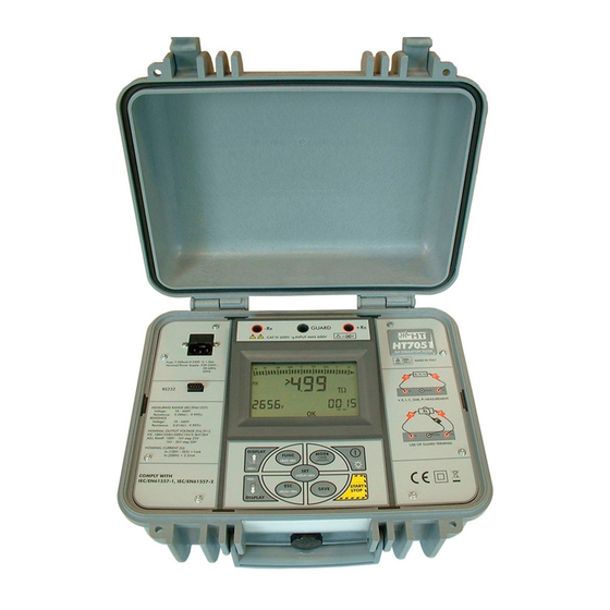
HT7051 - HT7051N 4 NOMENCLATURE 4.1 INSTRUMENT DESCRIPTION CAPTION: 1. Input bushings 2. Europlug socket 3. RS-232 connector 4. FUNC/ERASE MEM key 5. Multifunction arrow keys 6. ESC/RECALL MEM key 7. SET/DISPLAY MEM key 8. SAVE key 9. START/STOP key 10. -
Page 7: Description Of Display
HT7051 - HT7051N ESC/RECALL MEM key used for: Access to the data saved in the memory (if present) From a parameter setting screen or memory data display screen, pressing the key once allows returning to the previous screen SAVE key ... -
Page 8: Description Of Measuring Leads
HT7051 - HT7051N 4.4 DESCRIPTION OF MEASURING LEADS CAPTION: 1. Hand protection 2. Safety areas Fig. 2: Measuring leads 4.5 GUARD LEAD In some cases, measurements could be affected by surface currents. By applying voltage to an insulation to be measured, there may be two distinct currents: one flowing in the test piece, the other flowing on its surface. -
Page 9: Operating Instructions
HT7051 - HT7051N 5 OPERATING INSTRUCTIONS 5.1 SWITCH ON THE INSTRUMENT After switch on, the instrument gives a short acoustic signal and, for approximately one second, all segments of the display appear. Then, the instrument shows the firmware version, then it sets to the last measuring mode selected before turning off. -
Page 10: Insulation Measurement In Fix Mode
HT7051 - HT7051N 5.2 INSULATION MEASUREMENT IN FIX MODE This measurement mode, performed in compliance with IEC/ EN61557-2 guideline, allows a quick selection of the test voltage among the values: 250, 500, 1000, 2500, and 5000VDC. CAUTION The instrument may be used on installations of overvoltage category CAT IV 600V to earth with maximum voltage 600V between inputs. - Page 11 HT7051 - HT7051N By pressing the arrow keys, the instrument shows a screen similar to that reported here to the side, which contains the value of the input voltage. Press the MODE/CLEAR SMOOTH key to set one of the following test voltages:...
- Page 12 HT7051 - HT7051N While measuring, it is also possible to display the leakage current, the DAR (Dielectric Absorption Ratio if test duration > 1 minute), the PI (Polarization Index if test duration > 10 minutes) which cyclically show when pressing the arrow keys (see § 12.1) 10.
-
Page 13: Configuration Of The Test Parameters For Fix Mode
HT7051 - HT7051N 5.2.1 Configuration of the test parameters for FIX mode By cyclically pressing the SET/DISPLAY MEM key, it is possible to select the following parameters: Minimum value of the insulation (MIN) in a range between 0,01M - MAX ... -
Page 14: Insulation Measurement In Adjust Mode
HT7051 - HT7051N 5.3 INSULATION MEASUREMENT IN ADJUST MODE This function is performed in compliance with IEC/ EN61557-2 guideline. The ADJUST mode allows the fine adjustment of the test voltage between 100 - 5000VDC. CAUTION The instrument may be used on installations of overvoltage category CAT IV 600V to earth with maximum voltage 600V between inputs. - Page 15 HT7051 - HT7051N By pressing the arrow keys, the instrument shows a screen similar to that reported here to the side, which contains the value of the input voltage. Make sure that the set test voltage is the desired one. Should it not be the case, please refer to §...
- Page 16 HT7051 - HT7051N While measuring, it is also possible to display the leakage current, the DAR (Dielectric Absorption Ratio if test duration > 1 minute), the PI (Polarization Index if test duration > 10 minutes) which cyclically show when pressing the arrow keys (see §12.1)
-
Page 17: Configuration Of The Test Parameters For Adjust Mode
HT7051 - HT7051N 5.3.1 Configuration of the test parameters for ADJUST mode By cyclically pressing the SET/DISPLAY MEM key, it is possible to select the following parameters: Minimum value of the insulation (MIN) in a range between 0,01M - MAX ... -
Page 18: Insulation Measurement In Ramp Mode
HT7051 - HT7051N 5.4 INSULATION MEASUREMENT IN RAMP MODE This function is performed in compliance with standard IEC/ EN61557-2. The RAMP mode allows choosing among three different types of ramps: RAMP#1 RAMP#2 RAMP#3 For each type of ramp, it is possible to set the duration, the test voltage and the number of times the ramp is repeated (§... - Page 19 HT7051 - HT7051N The display shows a screen similar to that reported here to the side, which contains: The RAMP type selected The bar graph set to zero The indication "--- T" The set test voltage ...
- Page 20 HT7051 - HT7051N During measurement, the instrument gives a short acoustic signal every second and the display shows a screen similar to that reported here to the side, which contains: The RAMP function selected The bar graph proportional to the measured resistance value ...
- Page 21 HT7051 - HT7051N 10b. Once measurement is complete and any capacitance has been discharged, the instrument shows: The value measured insulation resistance The value of the actually generated voltage V1 The value of the time relevant to parameter T1 ...
-
Page 22: Configuration Of The Test Parameters For Ramp#1 Mode
HT7051 - HT7051N 5.4.1 Configuration of the test parameters for RAMP#1 mode By cyclically pressing the SET/DISPLAY MEM key, it is possible to select the following parameters: Minimum value of the insulation (MIN) in a range between 0,01M - MAX ... -
Page 23: Configuration Of The Test Parameters For Ramp#3 Mode
HT7051 - HT7051N 5.4.3 Configuration of the test parameters for RAMP#3 mode By cyclically pressing the SET/DISPLAY MEM key, it is possible to select the following parameters: Minimum value of the insulation (MIN) in a range between 0.01M - MAX ... - Page 24 HT7051 - HT7051N If, upon pressing the START/STOP key (with nominal test voltage set to 1000V and load resistance 5M), the capacitance at input leads -Rx, +Rx is > allowable limit capacitance, instrument gives a long acoustic signal and displays the screen reported here to the side for 3 seconds.
- Page 25 HT7051 - HT7051N If there are no data saved in the instrument’s memory, upon pressing ESC/RECALL key, instrument gives a long acoustic signal and displays the screen reported here to the side for 3 seconds. Afterwards, the instrument returns to the initial screen.
-
Page 26: Management Of Memory Data
HT7051 - HT7051N 6 MANAGEMENT OF MEMORY DATA 6.1 SAVE MEASUREMENTS After performing a measurement, press the SAVE key. The display shows a screen similar to that reported here to the side, which contains: The number of the memory location in which the measure will be saved ... -
Page 27: Recall Measurements
HT7051 - HT7051N 6.3 RECALL MEASUREMENTS Press the ESC/RECALL MEM key. The display shows a screen similar to that reported here to the side, which contains: The number of the last memory location used The value of parameter P Press the arrow keys to select the memory location whose content is to be displayed. -
Page 28: Maintenance
HT7051 - HT7051N 9 MAINTENANCE 9.1 GENERAL INFORMATION 1. During use and storage, carefully observe the recommendations listed in this manual in order to prevent possible damage or dangers during use 2. Do not use the instrument in environments with high humidity levels or at high temperatures. -
Page 29: Technical Specifications
HT7051 - HT7051N 10 TECHNICAL SPECIFICATIONS Accuracy is calculated as [% rdg + (dgt number * resolution)] at 23 ± 5°C,< 80%RH DC VOLTAGE Range Resolution Accuracy Protection against overloads 10 600V (2.0rdg+2 dgt) CAT IV 600V to earth... -
Page 30: Reference Guidelines
Dimensions (L x W x H): 360 x 310 x 195mm (14 x 12 x 8in) Weight: 3.5kg (7.8lb) Power supply External power supply: 220-240VAC, 50-60Hz, 20VA (HT7051) 110-120VAC, 50-60Hz, 20VA (HT7051N) Internal battery type: 1x4.8V, 3800mAh NiMH rechargeable by mains Recharging time: 4 hours... -
Page 31: Environment
HT7051 - HT7051N >1000 Test @ 5kV on 5M (Test time: 5sec, delay Battery life: between 2 test: 25sec) according to IEC/EN61557-2. (§ 6.7) Auto Power OFF: after 5 min of idleness AC measurement category: CAT II 240V (±10%) -
Page 32: Service
HT7051 - HT7051N 11 SERVICE 11.1 WARRANTY CONDITIONS This instrument is warranted against any material or manufacturing defect, in compliance with the general sales conditions. During the warranty period, defective parts may be replaced. However, the manufacturer reserves the right to repair or replace the product. -
Page 33: Theoretical Appendix
HT7051 - HT7051N 12 THEORETICAL APPENDIX 12.1 POLARIZATION INDEX (PI) PI is the ratio of Insulation Resistance values measured after 1 minute and after 10 minutes. The DC test voltage is present during the whole period of the measurement (an Insulation Resistance measurement is also running).
Need help?
Do you have a question about the HT7051 and is the answer not in the manual?
Questions and answers