Table of Contents
Advertisement
Quick Links
Advertisement
Table of Contents

Subscribe to Our Youtube Channel
Related Manuals for Supero SuperServer E200-8B


Summary of Contents for Supero SuperServer E200-8B
- Page 1 UPER ® SuperServer ® E200-8B USER'S MANUAL Revision 1.0...
- Page 2 The information in this User’s Manual has been carefully reviewed and is believed to be accurate. The vendor assumes no responsibility for any inaccuracies that may be contained in this document, makes no commitment to update or to keep current the information in this manual, or to notify any person or organization of the updates.
-
Page 3: About This Manual
Preface Preface About This Manual This manual is written for professional system integrators and PC technicians. It provides information for the installation and use of the server. Installation and maintainance should be performed by experienced technicians only. Please refer to the server specifications page on our Web site for updates on supported memory, processors and operating systems (www.supermicro.com). -
Page 4: Table Of Contents
SuperServer E200-8B User's Guide Contents Contacting Supermicro ..................vii Chapter 1 Introduction ................1-1 Overview ......................1-1 Motherboard Features ..................1-1 Processors ...................... 1-1 Memory ......................1-1 Serial ATA ......................1-2 I/O Ports ......................1-2 Server Chassis Features ................1-2 System Power ....................1-2 Hard Disk Drive .................... - Page 5 Table of Contents Connector Definitions ..................2-9 Front Control Panel ..................2-11 Jumper Settings .................... 2-14 Explanation of Jumpers ................2-14 CMOS Clear ....................2-14 Onboard Indicators ..................2-16 2-10 Serial ATA Connectors .................. 2-17 2-11 Installing Software ..................2-18 SuperDoctor 5 .....................
- Page 6 SuperServer E200-8B User's Guide Boot Settings ....................5-25 Save & Exit ....................5-27 Appendix A BIOS Error Beep Codes ............. A-1 Appendix B System Specifications ............B-1...
-
Page 7: Contacting Supermicro
Contacting Supermicro Headquarters Address: Super Micro Computer, Inc. 980 Rock Ave. San Jose, CA 95131 U.S.A. Tel: +1 (408) 503-8000 Fax: +1 (408) 503-8008 Email: marketing@supermicro.com (General Information) support@supermicro.com (Technical Support) Website: www.supermicro.com Europe Address: Super Micro Computer B.V. Het Sterrenbeeld 28, 5215 ML 's-Hertogenbosch, The Netherlands Tel: +31 (0) 73-6400390... - Page 8 SuperServer E200-8B User's Guide Notes viii...
-
Page 9: Overview
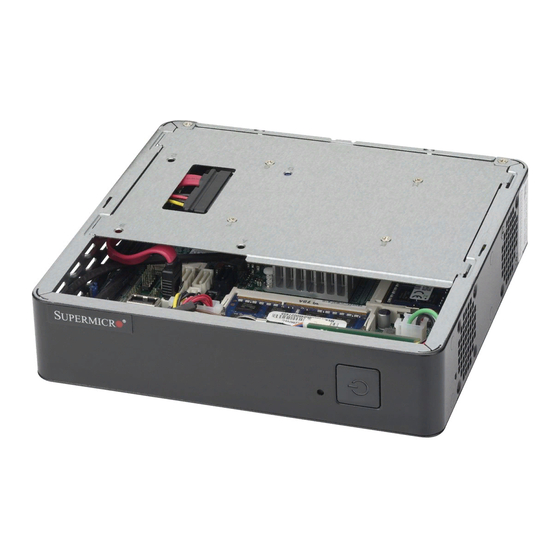
Chapter 1 Introduction Overview The SuperServer E200-8B is a compact, embedded system comprised of the SC101S chassis and the X10SBA single processor motherboard. Refer to our website for information on operating systems that have been certified for use with the system (www.supermicro.com). -
Page 10: Serial Ata
UPER ERVER E200-8B User's Manual Serial ATA The system supports one SATA drive, either SATA 2.0 (3Gbps) from Intel SoC SATA 3.0 (6Gbps) from Marvell 88SE9230. There is also a slot for one mSATA 2.0 card. I/O Ports The rear I/O ports include one HDMI port, one eDP (Display Port) port, one USB 3.0 port, one USB 2.0 port, two LAN ports and a VGA port. - Page 11 Chapter 1: Introduction DDI0 HDMI connector DUAL CHANNEL Non-ECC-SODIMM0 Intel BAY TRAIL-D DP connector DDI1 TI/HD3SS213ZQET Non-ECC-SODIMM1 eDP connector DDR3L 1333 MHz 4 Cores/8 Threads 2.7G/ 2M L2 Cache MAX. 8G SO-DIMM SUPPORTED VGA connector SATA 3Gb/s PCIe Gen2 x 2 SATA SATA[0] PCIE[0]...
-
Page 12: Server Installation And Setup
UPER ERVER E200-8B User's Manual Server Installation and Setup The server is shipped with the processor installed, and the motherboard installed in the chassis. Several steps are necessary to begin using your server. You must add memory, mount the hard disk drive, and mount the system in place. Unpacking the System Inspect the box in which the system was shipped and note if it was damaged. -
Page 13: System Interface
Chapter 1: Introduction System Interface The front of the chassis includes a power on/off push-button, including an LED status light, and a reset button. Power The main power button is used to apply or remove power from the power supply to the server system. - Page 14 UPER ERVER E200-8B User's Manual Notes...
-
Page 15: Handling The Motherboard
Chapter 2: Advanced Motherboard Setup Chapter 2 Advanced Motherboard Setup This section describes the connections on the motherboard and provides pinout definitions. Note that depending on how the system is configured, not all connections are required. The LEDs on the motherboard are also described here. A motherboard layout indicating component locations may be found in Chapter 1. -
Page 16: Onboard Processor
SUPERSERVER E200-8B User's Manual Onboard Processor The E200-8B features an embedded Intel Celeron J1900 processor. Installing Memory Memory Support The X10SBA motherboard supports up to a total of 8GB of low-voltage, Non-ECC DDR3-1333 SO-DIMM memory in two low-profile slots. Check the Supermicro website for a list of memory modules that have been validated. - Page 17 Chapter 2: Advanced Motherboard Setup Note: Due to memory allocation to system devices, the amount of memory that remains available for operational use will be reduced when 4 GB of RAM is used. The reduction in memory availability is disproportional. See the following table for details.
-
Page 18: Installing A So-Dimm Module
SUPERSERVER E200-8B User's Manual Installing a SO-DIMM Module 1. Align the receptive point on the bottom of the SO-DIMM module against the key on the memory socket. Note the notches on the side of the SO-DIMM module and those on the socket to avoid causing damage. -
Page 19: Connecting Cables
Chapter 2: Advanced Motherboard Setup Connecting Cables As an embedded system, there are a limited number of cables in the E200-8B. Data Cables The cables used to transfer data from the peripheral devices have been carefully routed to prevent them from blocking the flow of cooling air that moves through the system from front to back. -
Page 20: Rear I/O Ports
SUPERSERVER E200-8B User's Manual Rear I/O Ports The figure below describes the rear I/O ports on the system. Figure 2-3. Rear I/O Ports Rear I/O Port Locations Display Port LAN1 Port HDMI Port LAN2 Port USB1 Port (USB 2.0) VGA Port... -
Page 21: Motherboard Details
Chapter 2: Advanced Motherboard Setup Motherboard Details USB0(3.0) BIOS AUDIO FP FAN1 HDMI/DP USB1(2.0) JSPDIF_OUT LAN2 LAN1 (for mini-PCI-E only) X10SBA(-L) (for X10SBA only) Rev.1.01A LED3 LED2 (for X10SBA only) (for M-SATA only) BAR CODE JDIMM1 SODIMM2 (1.35V only) (for X10SBA) JBT1 JSD1 USB6... - Page 22 SUPERSERVER E200-8B User's Manual Connector Description Audio FP Front Panel Audio Header COM1-COM4 COM1/COM2/COM3/COM4 Headers Embedded DisplayPort (J5) Fan1/Fan2 System/CPU Fan Headers HDMI/DP HDMI/DisplayPorts mini-PCI-E Slot for a mini-PCI-E Card mSATA Slot MUX with I-SATA-1 (Available only when I-SATA1 is not in use.
-
Page 23: Connector Definitions
Chapter 2: Advanced Motherboard Setup Connector Definitions Note: some of the connectors on the motherboard are not described here as they are not needed in the E200-8B configuration, such as the ATX power connector. Universal Serial Bus (USB) Back Panel USB0 (2.0), Type A USB 6 Pin Definitions One Universal Serial Bus 2.0 port (USB0) Pin# Definition... - Page 24 SUPERSERVER E200-8B User's Manual HDMI Port One HDMI (High-Definition Multimedia Interface) Port is located on the I/O backpanel. This connector is used to display both high definition video and digital sound through an HDMI- capable display, using the same (HDMI) cable.
-
Page 25: Front Control Panel
Chapter 2: Advanced Motherboard Setup Front Control Panel The pinouts of the JFI (control panel) connector are shown below. Only one of these (those for the power button) are used on the E200-8B. Ground PWRLED 3.3 V HDD LED 3.3V Stby NIC1 Link LED 3.3V Stby 3.3V Stby... - Page 26 SUPERSERVER E200-8B User's Manual Fan Headers (Fan 1/Fan 2) The X10SBA has two fan headers (Fan Fan Header 1/Fan 2). These are 4-pin fan headers. Pin Definitions Although pins 1-3 of the fan headers are Pin# Definition backward compatible with the traditional...
- Page 27 Chapter 2: Advanced Motherboard Setup TPM Header (JTPM1) Trusted Platform Module Header Pin Definitions This header is used to connect a Trusted Pin # Definition Pin # Definition Platform Module (TPM), available from LCLK a third-party vendor. A TPM is a security LFRAME No Pin device that allows encryption and...
-
Page 28: Jumper Settings
SUPERSERVER E200-8B User's Manual Jumper Settings Explanation of Jumpers To modify the operation of the motherboard, jumpers can be used to choose between Connector Pins optional settings. Jumpers create shorts between two pins to change the function of the connector. Pin 1 is identified with a... - Page 29 Chapter 2: Advanced Motherboard Setup Manufacturer Mode Select Close pins 2 and 3 of jumper JPME2 to bypass SPI flash security and force the Manufacture Mode Select system to operate in the Manufacturer Jumper Settings Mode, allowing the user to flash the Jumper Setting Definition system firmware from a host server for...
-
Page 30: Onboard Indicators
SUPERSERVER E200-8B User's Manual Onboard Indicators LAN 1/LAN 2 LEDs GLAN 1/2 Activity Indicator LED Settings Two LAN ports (LAN 1/LAN 2) are located Color Status Definition on the I/O backpanel. Each Ethernet Yellow Flashing Active LAN port has two LEDs. The yellow LED... -
Page 31: 2-10 Serial Ata Connectors
Chapter 2: Advanced Motherboard Setup 2-10 Serial ATA Connectors The system supports one internal hard disk drive. 2-17... -
Page 32: 2-11 Installing Software
SUPERSERVER E200-8B User's Manual 2-11 Installing Software The Supermicro ftp site contains drivers and utilities for your system at ftp://ftp. supermicro.com. Some of these must be installed, such as the chipset driver. After accessing the ftp site, go into the CDR_Images directory and locate the ISO file for your serverboard. -
Page 33: Superdoctor ® 5
Chapter 2: Advanced Motherboard Setup SuperDoctor ® The Supermicro SuperDoctor 5 is a program that functions in a command-line or web-based interface in Windows and Linux operating systems. The program monitors system health information such as CPU temperature, system voltages, system power consumption, fan speed, and provides alerts via email or Simple Network Management Protocol (SNMP). -
Page 34: 2-12 Onboard Battery
SUPERSERVER E200-8B User's Manual 2-12 Onboard Battery Caution: There is a danger of explosion if the onboard battery is installed upside down, which will reverse its polarites (see Figure 2-9). This battery must be replaced only with the same or an equivalent type recommended by the manufacturer (CR2032). -
Page 35: Chapter 3 Chassis Components Setup
Chapter 3: Advanced Chassis Setup Chapter 3 Chassis Components Setup This chapter covers the steps required to install or replace components in the chassis. The only tool required is a Phillips screwdriver. Review the warnings and precautions listed in the manual before setting up or servicing this chassis. -
Page 36: Installing Mounting Brackets
SUPERSERVER E200-8B User's Manual Installing Mounting Brackets The chassis includes mounting brackets that allow it to be mounted in any convenient space in the work environment. Decide on a suitable location for the server. It should be situated in a clean, dust-free area that is well ventilated. -
Page 37: Removing The Chassis Cover
Chapter 3: Advanced Chassis Setup Removing the Chassis Cover Cover Hook Cover Hook Figure 3-2. Removing the Chassis Cover 1. Power down the system as described in section 3-1. 2. Remove the two side screws that hold the chassis cover in place and set these aside for later use. -
Page 38: Installing The Hard Drive
SUPERSERVER E200-8B User's Manual Installing the Hard Drive The SC101S can accommodate a single fixed 2.5" hard drive of 9.5 mm thickness. It is installed to a mounting tray inside the chassis. Figure 3-3. Installing the Hard Drive Installing the Hard Drive The motherboard should be installed before installing the hard drive. -
Page 39: Replacing The System Fan
Chapter 3: Advanced Chassis Setup Replacing the System Fan The SC101S includes one 4-cm system fan that provides cooling for the chassis. 1. Power down the system as described in section 3-1 and remove the AC power cord and the chassis cover. 2. - Page 40 SUPERSERVER E200-8B User's Manual Notes...
-
Page 41: Chapter 4 Standardized Warning Statements For Ac Systems
Chapter 4: Warning Statements for AC Systems Chapter 4 Standardized Warning Statements for AC Systems About Standardized Warning Statements The following statements are industry standard warnings, provided to warn the user of situations which have the potential for bodily injury. Should you have questions or experience difficulty, contact Supermicro's Technical Support department for assistance. - Page 42 SUPERSERVER E200-8B User's Manual Warnung WICHTIGE SICHERHEITSHINWEISE Dieses Warnsymbol bedeutet Gefahr. Sie befinden sich in einer Situation, die zu Verletzungen führen kann. Machen Sie sich vor der Arbeit mit Geräten mit den Gefahren elektrischer Schaltungen und den üblichen Verfahren zur Vorbeugung vor Unfällen vertraut.
- Page 43 Chapter 4: Warning Statements for AC Systems جسذٌة اصابة ًتتسبب ف حالة ٌوكي أى ًاًك ف خطز ًٌٌع هذا الزهز !تحذٌز الذوائز بالوخاطز الٌاجوة عي ي على علن ، ك هعذات تعول على أي قبل أى الكهزبائٍة حىادث أي وقىع وٌع...
-
Page 44: Installation Instructions
SUPERSERVER E200-8B User's Manual Installation Instructions Warning! Read the installation instructions before connecting the system to the power source. 設置手順書 システムを電源に接続する前に、 設置手順書をお読み下さい。 警告 将此系统连接电源前,请先阅读安装说明。 警告 將系統與電源連接前,請先閱讀安裝說明。 Warnung Vor dem Anschließen des Systems an die Stromquelle die Installationsanweisungen lesen. ¡Advertencia! Lea las instrucciones de instalación antes de conectar el sistema a la red de alimentación. -
Page 45: Circuit Breaker
Chapter 4: Warning Statements for AC Systems Circuit Breaker Warning! This product relies on the building's installation for short-circuit (overcurrent) protection. Ensure that the protective device is rated not greater than: 250 V, 20 A. サーキッ ト ・ ブレーカー この製品は、 短絡 (過電流) 保護装置がある建物での設置を前提としています。 保護装置の定格が250 V、... -
Page 46: Power Disconnection Warning
SUPERSERVER E200-8B User's Manual 경고! 이 제품은 전원의 단락(과전류)방지에 대해서 전적으로 건물의 관련 설비에 의존합니다. 보호장치의 정격이 반드시 250V(볼트), 20A(암페어)를 초과하지 않도록 해야 합니다. Waarschuwing Dit product is afhankelijk van de kortsluitbeveiliging (overspanning) van uw electrische installatie. Controleer of het beveiligde aparaat niet groter gedimensioneerd is dan 220V, 20A. - Page 47 Chapter 4: Warning Statements for AC Systems ¡Advertencia! El sistema debe ser disconnected de todas las fuentes de energía y del cable eléctrico quitado de los módulos de fuente de alimentación antes de tener acceso el interior del chasis para instalar o para quitar componentes de sistema. Attention Le système doit être débranché...
-
Page 48: Equipment Installation
SUPERSERVER E200-8B User's Manual Equipment Installation Warning! Only trained and qualified personnel should be allowed to install, replace, or service this equipment. 機器の設置 トレーニングを受け認定された人だけがこの装置の設置、 交換、 またはサービスを許可 されています。 警告 只有经过培训且具有资格的人员才能进行此设备的安装、更换和维修。 警告 只有經過受訓且具資格人員才可安裝、更換與維修此設備。 Warnung Das Installieren, Ersetzen oder Bedienen dieser Ausrüstung sollte nur geschultem, qualifiziertem Personal gestattet werden. -
Page 49: Restricted Area
Chapter 4: Warning Statements for AC Systems Waarschuwing Deze apparatuur mag alleen worden geïnstalleerd, vervangen of hersteld door geschoold en gekwalificeerd personeel. Restricted Area Warning! This unit is intended for installation in restricted access areas. A restricted access area can be accessed only through the use of a special tool, lock and key, or other means of security. -
Page 50: Battery Handling
SUPERSERVER E200-8B User's Manual אזור עם גישה מוגבלת !אזהרה יש להתקין את היחידה באזורים שיש בהם הגבלת גישה. הגישה ניתנת בעזרת .)'כלי אבטחה בלבד (מפתח, מנעול וכד محظورة مناطق ٍنتركُبها ف هذه انىحذة تخصيص تم ،أداة خاصت من خالل استخذاو... - Page 51 Chapter 4: Warning Statements for AC Systems Warnung Bei Einsetzen einer falschen Batterie besteht Explosionsgefahr. Ersetzen Sie die Batterie nur durch den gleichen oder vom Hersteller empfohlenen Batterietyp. Entsorgen Sie die benutzten Batterien nach den Anweisungen des Herstellers. Attention Danger d'explosion si la pile n'est pas remplacée correctement. Ne la remplacer que par une pile de type semblable ou équivalent, recommandée par le fabricant.
-
Page 52: Redundant Power Supplies
SUPERSERVER E200-8B User's Manual Redundant Power Supplies Note: Does not apply to this E200-8B server. Warning! This unit might have more than one power supply connection. All connections must be removed to de-energize the unit. 冗長電源装置 このユニッ トは複数の電源装置が接続されている場合があります。 ユニッ トの電源を切るためには、 すべての接続を取り外さなければなりません。... -
Page 53: Backplane Voltage (If Applicable To Your System)
Chapter 4: Warning Statements for AC Systems امداد الطاقة بوحدات عدة اتصاالت جهاز ال يكون لهذا قد الكهرباء عن وحدة ال لعسل كافة االتصاالت يجب إزالة 경고! 이 장치에는 한 개 이상의 전원 공급 단자가 연결되어 있을 수 있습니다. 이 장치에... -
Page 54: Comply With Local And National Electrical Codes
SUPERSERVER E200-8B User's Manual מתח בפנל האחורי !הרה אז קיימת סכנת מתח בפנל האחורי בזמן תפעול המערכת. יש להיזהר במהלך .העבודה اللىحة أوالطاقة المىجىدة على التيار الكهزبائي مه خطز هناك هذا الجهاس خدمة كه حذرا عند يعمل النظام عندما يكىن... -
Page 55: Product Disposal
Chapter 4: Warning Statements for AC Systems Attention L'équipement doit être installé conformément aux normes électriques nationales et locales. תיאום חוקי החשמל הארצי !אזהרה הציוד חייבת להיות תואמת לחוקי החשמל המקומיים והארציים התקנת المتعلقة المحلية والىطىية قىاويه يجب أن يمتثل لل الكهربائية... -
Page 56: Hot Swap Fan Warning (If Applicable To Your System)
SUPERSERVER E200-8B User's Manual ¡Advertencia! Al deshacerse por completo de este producto debe seguir todas las leyes y reglamentos nacionales. Attention La mise au rebut ou le recyclage de ce produit sont généralement soumis à des lois et/ou directives de respect de l'environnement. Renseignez-vous auprès de l'organisme compétent. - Page 57 Chapter 4: Warning Statements for AC Systems 警告 當您從機架移除風扇裝置,風扇可能仍在轉動。小心不要將手指、螺絲起子和其他 物品太靠近風扇。 Warnung Die Lüfter drehen sich u. U. noch, wenn die Lüfterbaugruppe aus dem Chassis genommen wird. Halten Sie Finger, Schraubendreher und andere Gegenstände von den Öffnungen des Lüftergehäuses entfernt. ¡Advertencia! Los ventiladores podran dar vuelta cuando usted quite ell montaje del ventilador del chasis.
-
Page 58: Power Cable And Ac Adapter
SUPERSERVER E200-8B User's Manual Power Cable and AC Adapter Warning! When installing the product, use the provided or designated connection cables, power cables and AC adaptors. Using any other cables and adaptors could cause a malfunction or a fire. Electrical Appliance and Material Safety Law prohibits the use of UL or CSA -certified cables (that have UL/CSA shown on the code) for any other electrical devices than products designated by Supermicro only. - Page 59 Chapter 4: Warning Statements for AC Systems Attention Lors de l'installation du produit, utilisez les bables de connection fournis ou désigné. L'utilisation d'autres cables et adaptateurs peut provoquer un dysfonctionnement ou un incendie. Appareils électroménagers et de loi sur la sécurité Matériel interdit l'utilisation de UL ou CSA câbles certifiés qui ont UL ou CSA indiqué...
- Page 60 SUPERSERVER E200-8B User's Manual Notes 4-20...
-
Page 61: Chapter 5 Bios
Chapter 5: BIOS Chapter 5 BIOS Introduction This chapter describes the AMI BIOS setup utility for the X10SBA (-F). The ROM BIOS is stored in a Flash EEPROM and can be easily updated. This chapter describes the basic navigation of the AMI BIOS setup utility screens. Note: For AMI BIOS recovery, please refer to the UEFI BIOS Recovery Instructions in Appendix C. -
Page 62: How To Start The Setup Utility
SuperServer E200-8B User's Guide How to Start the Setup Utility Normally, the only visible Power-On Self-Test (POST) routine is the memory test. As the memory is being tested, press the <Delete> key to enter the main menu of the AMI BIOS setup utility. From the main menu, you can access the other setup screens. - Page 63 Chapter 5: BIOS System Date/System Time Use this option to change the system date and time. Highlight System Date or System Time using the arrow keys. Enter new values using the keyboard. Press the <Tab> key or the arrow keys to move between fields. The date must be entered in Day MM/DD/YYYY format.
-
Page 64: Advanced Setup Configurations
SuperServer E200-8B User's Guide Advanced Setup Configurations Use the arrow keys to select Advanced Setup and press <Enter> to access the submenu items: Aptio Setup Utility - Copyright (C) 2013 American Megatrends, Inc. Main Advanced Boot Security Save & Exit System Boot Feature Setting ... -
Page 65: Power Configuration
Chapter 5: BIOS Wait For 'F1' If Error This feature forces the system to wait until the 'F1' key is pressed if an error occurs. The options are Disabled and Enabled. Interrupt 19 Capture Interrupt 19 is the software interrupt that handles the boot disk function. When this item is set to Enabled, the ROM BIOS of the host adaptors will "capture"... -
Page 66: Chipset Configuration
SuperServer E200-8B User's Guide Chipset Configuration Warning! Setting the wrong values in the following sections may cause the system to malfunction. North Bridge The following North Bridge information will be displayed: Graphics Configuration This item displays the following graphics information:... -
Page 67: South Bridge
Chapter 5: BIOS DVMT Total Gfx Mem Use this feature to set the total memory size to be used by the internal graphics devices based on the DVMT 5.0 platform. The options are 128MB, 256MB and MAX. Aperture Size Use this feature to set the Aperture size, which is the size of system memory reserved by the BIOS for graphics device use. -
Page 68: Usb Configuration
SuperServer E200-8B User's Guide Azalia HDMI Codec Select Enabled to enable the internal HDMI CODEC (Coder-Decoder) for Azalia. The settings are Enabled and Disabled. USB Configuration Legacy USB Support This feature enables support for legacy USB devices. Select Auto to disable legacy support if USB devices are not present. -
Page 69: Pci Express Configuration
Chapter 5: BIOS USB Port 2 Select Enabled for USB Port 2 support. The options are Enabled and Disabled. USB Port 3 Select Enabled for USB Port 3 support. The options are Enabled and Disabled. PCI Express Configuration This item displays the information of onboard PCI-E slots. PCI Express Port 0 This item enables or disables the PCI Express Port 0 on the motherboard. -
Page 70: Super Io Configuration
SuperServer E200-8B User's Guide in synchronizing multimedia streams, providing smooth playback and reducing the dependency on other timestamp calculation devices, such as an x86 RDTSC Instruction embedded in the CPU. The High Performance Event Timer is used to replace the 8254 Programmable Interval Timer. The options are Enabled and Disabled. -
Page 71: Hardware Health Configuration
Chapter 5: BIOS The options for Serial Port 4 are Auto, (IO=2E0h; IRQ=4), (IO=3F0h; IRQ=3, 4, 5, 6, 7, 10, 11, 12), (IO=3E0h; IRQ=3, 4, 5, 6, 7, 10, 11, 12), and (IO=3D0h; IRQ=3, 4, 5, 6, 7, 10, 11, 12). Hardware Health Configuration ... -
Page 72: Console Redirection Settings
SuperServer E200-8B User's Guide Console Redirection Settings This feature allows the user to specify how the host computer will exchange data with the client computer, which is the remote computer used by the user. Terminal Type This feature allows the user to select the target terminal emulation type for Console Redirection. - Page 73 Chapter 5: BIOS VT-UTF8 Combo Key Support Select Enabled to enable VT-UTF8 Combination Key support for ANSI/VT100 terminals. The options are Enabled and Disabled. Recorder Mode Select Enabled to capture the data displayed on a terminal and send it as text messages to a remote server.
- Page 74 SuperServer E200-8B User's Guide Out-of-Band Management Port The feature selects a serial port used by the Microsoft Windows Emergency Management Services (EMS) to communicate with a remote server. The default setting is COM0. Terminal Type This feature allows the user to select the target terminal emulation type for Console Redirection.
-
Page 75: Cpu Configuration
Chapter 5: BIOS CPU Configuration Socket 0 CPU Configuration The following CPU information will be displayed: • Type of CPU • CPU Signature • Microcode Patch • Max (Maximum) CPU Speed • Min (Minimum) CPU Speed • Processor Cores •... -
Page 76: Sata Configuration
SuperServer E200-8B User's Guide cannot, thus preventing a worm or a virus from flooding illegal codes to overwhelm the processor or damage the system during an attack. The default is Enabled. (Refer to Intel and Microsoft Web Sites for more information.) - Page 77 Chapter 5: BIOS SATA Mode (Available when the item: Serial-ATA is enabled) This item selects the mode for the installed SATA drives. The options are IDE Mode, and AHCI Mode. If the item above -SATA Mode Select is set to AHCI, the following items are displayed: Serial-ATA Port 0/ Serial-ATA Port 1 Select Enabled to enable a SATA port specified by the user.
- Page 78 SuperServer E200-8B User's Guide PCIe/PCI/PnP Configuration This feature allows the user to set the PCI/PnP configurations for the following items: VGA Palette Snoop Select Enabled to support VGA palette register snooping which will allow the PCI cards that do not contain their own VGA color palette to examine the video cards palette and mimic it for proper color display.
- Page 79 Chapter 5: BIOS Slot1 PCI-E 2.0 x2 (in x8) OPROM Use this feature to enable or disable PCI-Express slot Option ROM support to boot the computer using a device installed on the slot specified by the user. The options are Disabled, Legacy, EFI, and EFI and Legacy. Onboard LAN1 Option ROM/Onboard LAN2 Option ROM Select iSCSI to use the iSCSI Option ROM to boot the computer using an iSCSI device installed in a LAN port specified.
-
Page 80: Iscsi Configuration
SuperServer E200-8B User's Guide iSCSi Configuration iSCSI Initiator Name This feature allows the user to enter the unique name of the iSCSI Initiator in IQN format. Once the name of the iSCSI Initiator is entered into the system, configure the proper settings for the following items. - Page 81 Chapter 5: BIOS PORT CONFIGURATION INFORMATION The following port configuration information will be displayed: UEFI Driver: Adapter PBA: Chip Type: PCI Device ID: Bus: Device: Function: Link Status MAC Address: Virtual MAC Address: 5-21...
-
Page 82: Security Settings
SuperServer E200-8B User's Guide Security Settings This menu allows the user to configure the following security settings for the system. Aptio Setup Utility - Copyright (C) 2013 American Megatrends, Inc. Main Advanced Security Exit Boot Password Description Set Administrator Password. - Page 83 Chapter 5: BIOS Key Management Default Keys Provision Select Enable to install all manufacture defaults for the following system security settings. The options are Disabled and Enabled. Delete All Secure Boot Variables This feature allows the user to delete all secure boot settings previous stored in the system.
- Page 84 SuperServer E200-8B User's Guide Authorized Signatures Delete DB (DataBase) Select <Yes> to confirm deletion of a database from the NVRAM (Non-Volatile RAM). Set New DB (DataBase) Select <Yes> to confirm that a new database will be set in the NVRAM (Non-Volatile RAM).
-
Page 85: Boot Settings
Chapter 5: BIOS Boot Settings Use this feature to configure Boot Settings: Aptio Setup Utility - Copyright (C) 2013 American Megatrends, Inc. Main Advanced Security Boot Exit Boot Priority Sets the system boot order Boot Order #1 [UEFI Hard Disk] Boot Order #2 [UEFI CD/DVD] Boot Order #3... - Page 86 SuperServer E200-8B User's Guide Hard Disk Drive BBS Priorities • Boot Order #1 CDROM/DVD Drive BBS Priorities • Boot Order #1 Network Drive BBS Priorities • Boot Order #1 USB Key Drive BBS Priorities • Boot Order #1 ...
-
Page 87: Save & Exit
Chapter 5: BIOS Save & Exit Select the Exit tab from the BIOS setup utility screen to enter the Exit BIOS Setup screen. Aptio Setup Utility - Copyright (C) 2013 American Megatrends, Inc. Main Advanced Security Boot Save & Exit Exit system setup after saving the Discard Changes and Exit changes. - Page 88 SuperServer E200-8B User's Guide Save As User Defaults To set this feature, select Save as User Defaults from the Exit menu and press <Enter>. This enables the user to save any changes to the BIOS setup for future use. Restore User Defaults To set this feature, select Restore User Defaults from the Exit menu and press <Enter>.
-
Page 89: Appendix A Bios Error Beep Codes
Appendix A: BIOS Error Beep Codes Appendix A BIOS Error Beep Codes During the POST (Power-On Self-Test) routines, which are performed each time the system is powered on, errors may occur. Non-fatal errors are those which, in most cases, allow the system to continue with bootup. - Page 90 SuperServer E200-8B User's Guide Notes...
-
Page 91: Appendix B System Specifications
Appendix B: System Specifications Appendix B System Specifications Processors One Intel Celeron J1900 SoC (System on a Chip) 64-bit, 22 nm low-power quad- processor BIOS 16MB SPI Flash EEPROM with AMI® BIOS Memory Capacity Two sockets that can support up to 8GB of low-voltage, Non-ECC DDR3-1333 SO-DIMM memory. -
Page 92: Operating Environment
SUPERSERVER E200-8B User's Manual Operating Environment Operating Temperature: 0º to 40º C (32º to 104º F) Non-operating Temperature: -20º to 60º C (-40º to 140º F) Operating Relative Humidity: 10% to 85% (non-condensing) Non-operating Relative Humidity: 10% to 95% (non-condensing)
Need help?
Do you have a question about the SuperServer E200-8B and is the answer not in the manual?
Questions and answers