Table of Contents
Advertisement
Advertisement
Table of Contents

Related Manuals for Eneo PXD-2080MIR


Summary of Contents for Eneo PXD-2080MIR
- Page 1 Full Manual Mega Pixel Network Dome Camera PXD-2080MIR...
-
Page 2: Table Of Contents
Contents Notes on Safety ......................4 General Description ....................4 Scope of delivery .....................4 Description of parts ....................5 Installation .........................6 Surface Mount .......................6 Flush Mount ......................7 Setup of the Zoom and FOCUS ................7 Limit of Pan and Tilt ....................8 Power Supply Connections ..................8 EMI Ferrite Core Connections ................9 Setup Menu .......................9 In the menu ......................9... - Page 3 Specifications ......................23 Smart Viewer User‘s Manual ............. Appendix A Web Admin User‘s Manual ..............Appendix B...
-
Page 4: Notes On Safety
Notes on Safety Please also pay attention to the enclosed safety instructions, and carefully read through this instruction guide before initial operation. Important points of advice are marked with a caution symbol. General Description Mega Pixel IP camera which realizes 1.3M, 1280x720(30p/25p) or 2.0M, 1920x1080(30p/25p). Serves real time live view Max 30fps live view @ 1280x720p &... -
Page 5: Description Of Parts
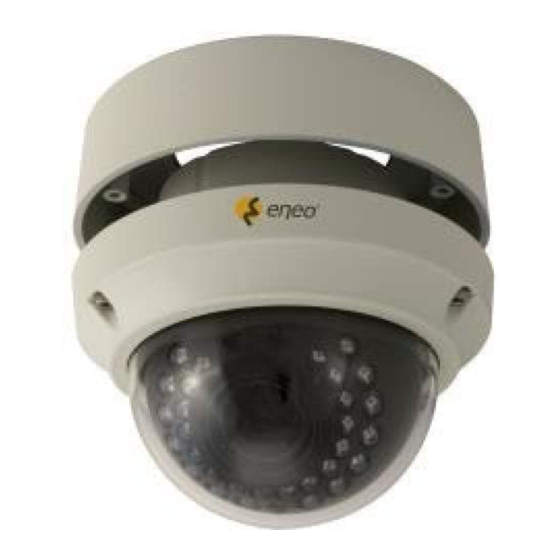
Description of parts ⓐ ⓑ ⓒ ⓓ ⓐ Zoom & Focus ⓑ Lens hood ⓒ Light sensor for IR LEDs ⓓ IR LED ⓔ ⓕ ⓖ ⓗ ⓔ Dome base ⓕ Mount holes (x3) for dome base ⓖ OSD control joy stick ⓗ... -
Page 6: Installation
Installation Surface Mount Locate the mounting template at the installation Ceiling or wall position and drill the ceiling or wall if needed. Place mount base on pre-drilled position and fix it through mount base mount holes ⓝ (4x) by using mount screws. Assemble the cable pipe, otherwise tighten blind cover. -
Page 7: Flush Mount
Flush Mount Ceiling or wall Locate the mounting template at the installation position and drill the ceiling or wall if needed. Open Dome bubble assembly by loosening ⓙRing cover fixing screws(x3) Dome base CAUTION Extreme care should be taken NOT to scratch the dome surfaces and to protect it from dirt or dust at any time. -
Page 8: Limit Of Pan And Tilt
3) Adjust Zoom & Focus. 4) Enter SETUP menu again. 5) Restore FACTORY DEFAULT by MAIN menu-2>CAMERA RESET (See 7.15 CAMERA RESET). 6) Save the restored parameters by moving cursor to SAVE ALL and pressing ● button. 7) Set all other functions if necessary. 8) Save the changes by moving cursor to SAVE ALL and pressing ●... -
Page 9: Emi Ferrite Core Connections
AUDIO IN AUDIO OUT AC24V/GND AC24V/DC12V GRN ALM IN / GRNWHT GND BLU ALM OUT / BLUWHT GND LAN CABLE with RJ-45 and PRO- TECTION CAP EMI Ferrite Core Connections Please connect EMI Ferrite Core as shown below. Setup Menu In the menu Setup menu can be accessed and controlled by OSD control joy stick on the side of camera. -
Page 10: Main Menu
SYMBOL descriptions for joystick operation ▲,▼,◄,► denotes the directions of Joystick lever operation. ● denotes Pressing straight down of Joystick lever In the menu, use ▲,▼ to move menu, ◄,► to change the settings and press ● to select or enter. FACTORY DEFAULT values in this manual may NOT be the same as the default values by FACTORY SET due to the changes for the improvements or the customer‘s requirements. -
Page 11: Exposure Menu
EXPOSURE Menu To enter EXPOSURE menu, press ● at MAIN>EXPOSURE. EXPOSURE Factory Descriptions Default SHUTTER AUTO 1. SHUTTER is recommended to set to AUTO instead of 1/50s (1/60s) for 1.3MP ver. and 1/25s (1/30s) for 2MP ver. if auto iris lens is equipped. 2. -
Page 12: Blc Menu
D-WDR D-WDR enhances the brightness at dark area of the scene by increasing the the gain partially. White spot noises may increase in the dark area if it is set to too high. DEFOG Enhances visibility at foggy scene. The performance is very limited. This function does not work with the clean scene. -
Page 13: Hsblc Menu
HSBLC Menu To enter HSBLC menu, press ● at EXPOSURE > BACKLIGHT > HSBLC. HSBLC cuts out and fills the highlighted area with black. The cut out area is excluded in determining the light level by the signal processor. HSBLC has four windows and they can be set independently in size, position, level and etc. -
Page 14: Lens Menu
LENS Menu Lens can be selected either DC or MANUAL lens. Lens MUST be set to DC for the best image when DC iris lens is installed. Select Lens mode OUTDOOR or INDOOR according to installation place. Horizontal wave or bar may be seen when MANUAL is selected and the camera is working under florescent or similar lights. -
Page 15: Day/Night Menu
DAY/NIGHT Menu DAY&NIGHT menu can be set to AUTO, COLOR, B/W or EXT. In AUTO, camera determines DAY or NIGHT by the incoming light level through the lens only and IR CUT FILTER switches following the DAY/NIGHT modes. In COLOR, camera disables DAY/NIGHT feature and works as a regular color camera and IR CUT FILTER is inserted to cut out the infrared spectrum from the light. -
Page 16: Nr Menu
IMPORTANT!!! DAY->NIGHT and NIGHT->DAY operations must be examined and verified at the final step of the installation. Block the lens for a few seconds for NIGHT mode and release and let it return to DAY mode. If camera stays at NIGHT mode more than 10sec, decrease N-->D(THRES) a little and repeat the fore- mentioned steps. -
Page 17: Pict Adj. Menu
2D&3D NR Factory Default Descriptions 2DNR ON enables two dimensional noise reduction. Noise Reduction is effective at low light. 3DNR ON enables three dimensional noise reduction. Noise Reduction is effective at low light. Starting or Ending of noise reduction with respect to light level can be set. In 3DNR menu, START THRES sets the point from which level 3DNR starts while the illumination goes dim. -
Page 18: Special Menu
MONITOR Sets LCD or CRT For LCD, GAMMA, BLUE GAIN or RED GAIN is adjustable for the best view with LCD monitor. Low GAMMA compensates the dark area a little but contrast becomes less a little. High GAMMA increases contrast but looses the visibility at dark area. For CRT, BLACK LEVEL, BLUE GAIN or RED GAIN is adjustable. -
Page 19: Cam Title Menu
SPECIAL Factory Default Descriptions CAM TITLE If set to ON, CAM TITLE is displayed on the screen. (See CAM TITLE for detail) MOTION If set to ON, motion is displayed on the monitor by means of digital effect. (See MOTION for settings) PRIVACY If set to ON, up to 8 privacy masks are displayed on the monitor by means of blocks. -
Page 20: Motion Menu
MOTION menu Up to 3 motions detection areas can be programmed in size, position, sensitivity and display on/off. If MOTION in MAIN>SPECIAL menu is set to ON, ‘MOTION’ is displayed on the monitor whenever the motion is detected and the mosaic effect appears on the motioned area if MOTION VIEW is set to ON. -
Page 21: Pixel Comp Menu
PRIVACY Factory Default Descriptions SELECT AREA1 Selects the area to be adjusted out of AREA1~AREA8. WINDOW ON displays the selected window and enables the privacy mask for that area. POSITION and SIZE can be set after pressing when WINDOW is ON. ‚POSITI- ON‘... -
Page 22: Dimensional Drawings
DO STATIC – Pressing will execute STATIC DPC. Camera closes the lens automatically and detects the defect pixels. CAUTION: Lens cap is highly recommended for closing because the iris of some lens is not closed perfectly. STATIC THR LEVEL is a threshold for white dot noise level caused by a defect pixel and is effective for STATIC DPC only. -
Page 23: Specifications
Specifications MODEL PXD-2080MIR Imaging Sensor 1/3” Panasonic Progressive scan MAICOVICON RGB CMOS Total Pixels 2010H x 1108V Effective Pixels 1944H x 1092V Min. Illumination 0.003Lux @B/W, 4x Sense-UP, F1.4, 40Ire Output Video Resolution 1920x1080 30p/25p S/N ratio 50dB(AGC off) Day & Night... - Page 24 Smart Viewer User's Manual Smart Viewer User's Manual Version 1.1.0.4 eneo eneo 1...
- Page 25 Document Version: 1.1.0.5 About This Document This document is prepared for users of Smart Viewer and eneo products supplied by eneo. It is assumed that the users are familiar with Microsoft Windows operating systems and Web browsers such as Internet Explorer.
- Page 26 Getting Audio from Server ....................15 6.1.2. Sending Audio to Server ....................15 6.1.3. Mute Audio........................15 6.2. Relay Output Control ......................... 15 6.3. P/T/Z Control ..........................16 Control Toolbar ........................... 18 Troubleshooting ..........................19 8.1. Installation ..........................19 eneo 3...
- Page 27 Smart Viewer User's Manual 8.2. Server ............................19 8.3. Video ............................19 8.4. Audio ............................20 8.5. PTZ Function ..........................21 8.6. Relay Output ..........................21 8.7. Others ............................21 eneo 4...
-
Page 28: Key Features
TCP/IP network. Smart Viewer works with SmartNVR network video software, eneo Network Video Servers, Network Video Recorders, and Network Cameras to show real-time live video images and enables users to control audio, Relay Output, and PTZ functions. -
Page 29: Installing And Uninstalling
2.1. Installing Smart Viewer Connect to the eneo Server on Internet Explorer, and click Live View on the main page. Then Smart Viewer will be automatically downloaded and installed. If the Internet connection is not available, it's possible to manually install the program file in advance and connect to the eneo Server later. -
Page 30: Manual Installation
When the Internet connection is not available or having some difficulties, you can manually download and install the Smart Viewer program file. Execute the downloaded file, and you will see the Smart Viewer Setup Wizard window as shown above. Click the Install button to start installing. The following window will be displayed during the installation. eneo... - Page 31 There are two ways to uninstall Smart Viewer program from your computer. Before uninstalling, close all the Internet Explorer windows. 2.2.1. Uninstalling with Program Menu Click the Uninstall and the following window will be shown. Click the Yes button. eneo...
- Page 32 Smart Viewer User's Manual If the uninstalling is successful, the following window will be displayed. Click OK to finish. 2.2.2. Uninstalling on Control Panel Click Start button on the screen, then select the Control Panel. eneo...
- Page 33 Smart Viewer User's Manual In the Control Panel window, double-click the Add or Remove Programs icon. You will see the Currently installed programs list. Click Smart Viewer button, and then click Change/Remove button. It will start uninstalling process then. eneo...
- Page 34 Smart Viewer User's Manual 3. Starting Smart Viewer Once Smart Viewer is installed in your computer, you can start it by connecting to the eneo Server on Internet Explorer and select Live View on the main menu. The appearance of Smart Viewer window varies depending on what type of eneo Server is connected to Network Video Server, Network Camera Server, or Network Video Recorder.
- Page 35 Displays or hide channels. Set up the frame rate, video pause, storing images or Channel Control Bar video, Relay Output control, audio mute, FES data indication. Audio Control Bar Adjust audio control of eneo Server and volume of MIC and Speaker. PTZ Control Bar Control PTZ function. Live View screen Display live view video of eneo Server.
-
Page 36: Video Control
In Smart Viewer, Live video currently displayed can be captured and saved as image file either in JPEG or BMP format. Select the live view video you want save, and click Snapshot button on OSD Channel Buttons. The following window will be displayed. eneo... - Page 37 In Smart Viewer, Live video currently displayed can be captured and recorded as a video file in AVI format. Select a live view you want to save, and click Rec Avi button on OSD Channel Buttons. Clicking it again will finish recording. Max duration is 10 minutes and recording will be stopped after 10 min. eneo...
- Page 38 When you play back the recorded video, the time stamp will be displayed as a subtitle on the video screen as shown the picture below. Note: When you play back videos recorded from MPEG-4 or H.264, proper CODEC’s may be required. eneo...
- Page 39 For the Products with local storage such as NVR or NVS & NC with Micro SD, the Instant Playback is supported. Clicking the Instant Playback button from OSD menu will open below window. Instant playback will scan the video data up to 1 min before it was executed. And scanned data will be played automatically eneo...
-
Page 40: Extended Features
5.3. Extended Features When you click the right mouse button on the Live View Window, a pop-up menu will appear for extended features as shown below. 5.3.1. Pausing Live Video Click the Pause button to stop and resume live view video. eneo... - Page 41 5.3.4. Navigate on Mini Window Mini window helps users to find which portion of entire live view is being displayed. Mini window can be displayed or hidden. Click the right mouse button on the Live View Screen and select the Navigation. eneo...
- Page 42 6.2. Relay Output Control By using Relay Output control, you can control external devices connected to eneo Servers or cameras. It can be turning lights on and off, starting alarms, and etc. To control Relay Output, click the right mouse button on the Live...
- Page 43 Viewer. You will also be able to use a Joystick to control PTZ device if your computer has a Joystick connected to it. Connect a PTZ-enabled camera to the eneo Server, go to the Admin menu of the Web page, and then set up the PTZ parameters as described in eneo Server User’s manual.
- Page 44 Move the camera automatically to the preset position as it is configured in PTZ Preset Call control on eneo Server. Moving cameras in two different modes: Step and Continuous modes. Step mode: Camera moves as much as previously defined each time. This mode PTZ Move Mode is effective for remote cameras with slow network condition.
-
Page 45: Control Toolbar
Redraw the live video after median calculation if it’s smaller than the original size. (Turing on this feature will increase CPU usage) Display the version information of Smart Viewer. (FES version and type will be also shown if installed) eneo... -
Page 46: Troubleshooting
Q) ‘Connecting’ or ‘Disconnected’ message is displayed during live view. A) It may be caused by either the network is not available or eneo Server is turned off or rebooting. Check if the network is working properly and eneo Server is turned on. If you still see the same message while the network is good and the power is on, try rebooting the eneo Server. - Page 47 Q) I can't send audio to eneo Server. A) Sending audio from Smart Viewer to eneo Server is only allowed to the user who used that feature for the first time. Any other user can only receive audio from the server. Check if the computer has the sound card driver properly installed.
-
Page 48: Ptz Function
8.5. PTZ Function Q) PTZ Control bar is not activated. A) Connect to eneo Server, and make sure PTZ set up is properly done on Admin menu. Q) Clicking PTZ buttons doesn’t work. A) When network condition is not good enough, there may be some latency time in camera movement. Try Step Mode if Move mode is currently set to Continuous. - Page 49 Web Admin User’s Manual Version 4.15...
- Page 50 ENEO Admin User’s Manual Index Admin Menu of eneo Servers ........................6 1.1. Entering Admin Menu ........................6 1.2. Admin Menu Structure ........................7 Quick Configuration ............................9 2.1. Step 1: Changing Server Name ....................10 2.2. Step 2: Time Setup ......................... 11 2.3.
- Page 51 ENEO Admin User’s Manual 4.1.1. Static IP Configuration ......................18 4.1.2. DHCP Client Configuration ....................19 4.1.3. PPPoE Configuration ......................19 4.2. Network Ports ........................... 19 4.3. Bandwidth Control Configuration ................... 20 4.4. View Network Status ........................21 4.5. Network Status Notify ........................22 4.6.
- Page 52 ENEO Admin User’s Manual 6.1.1. E-mail Service Configuration..................... 39 6.1.2. FTP (Buffered) Service Configuration ................43 6.1.3. FTP (Periodic) Service Configuration ................45 6.1.4. Sensor Notification Service Configuration ..............47 6.1.5. Sensor Notification Service Configuration for Each Input ........48 6.1.6.
- Page 53 Document Version: 4.15 About This Document This document is prepared for users of eneo products supplied by eneo. It is assumed that the users are familiar with network equipment such as LAN, Hub, router, and having basic knowledge of network terminologies. If you have any questions regarding network installations, please contact your network equipment vendor or network administrator or Internet service providers.
- Page 54 1. Admin Menu of eneo Servers After connecting to a eneo server on the web browser, you’ll find the web page as shown below. The rightmost item of the menu is Admin, where you can set up the most of features in...
- Page 55 ENEO Admin User’s Manual 1.1. Entering Admin Menu Click Admin item of the menu, then you’ll see a login window. In the login window, enter root for both ID and password as they are the factory defaults. Press Enter key or click OK button.
- Page 56 ENEO Admin User’s Manual Level 2 Sub- Category Main Menu Level 1 Sub-Menu Menu Step 1 Step 2 Step 3 Quick configuration Step 4 Step 5 Finish Server Name Date & Time System Admin. Password Configuration Access Control User Registration...
- Page 57 ENEO Admin User’s Manual Primary stream Secondary stream DI/DI Camera 1 DI Status / DO Control Camera 1 E-mail Camera 2 Camera 1 FTP(Buffered) Camera 2 Camera 1 FTP(Periodic) Camera 2 Camera 1 Sensor Notification Camera 2 Advanced Advanced Services...
-
Page 58: Quick Configuration
ENEO Admin User’s Manual Camera 4 Recording Profile Recording Mode SD Status Report Clear Recording Config. Delete Recorded Data System Log Save Configuration Utilities Reboot Factory Default System Update Quick Configuration In Quick Configuration, you will be able to set up many of the essential parts of the configuration in a simple manner without going into details. - Page 59 2.4. Step 4: IP-CCTV DNS When eneo Server is used in a Dynamic IP environment, it is required to utilize IP-CCTV DNS feature. See the section 4.6 IP-CCTV DNS Setup in page 24 to see how to set up. 2.5.
-
Page 60: System Configuration Menu
Click Step 1 on Quick Configuration, then the following will be displayed and you will find out the system information such as model number of the eneo Server, server name, MAC address (serial number), firmware version, and Web image version. - Page 61 Note: In order to retrieve Time and Date information from a NTP server, you need to put NTP server address in advance of setting up, such as pool.ntp.org. retrieved from eneo® Server. Then click Apply button to save it. 3.3. Admin Password To change the password for the administrator, click Admin Password on System Configuration menu.
- Page 62 Apply button to put it into effect. Because you have replaced the password with a new one, the existing network connection made with old password to eneo Server is lost now. You will have to reconnect to the eneo server using new password.
- Page 63 ENEO Admin User’s Manual 3.5. User Registration You can add, modify, or delete users for your eneo Server here. Once registered as Limited Access setting, the user can access the eneo Server with some limited privileges. 3.5.1. Add When Add is selected, you can add users and define their passwords, names, and access permission levels respectively.
- Page 64 ENEO Admin User’s Manual eneo Server can have multiple VS modules registered in it. When user ticks on any of Enable checkboxes, other fields in that row are enabled to select. VS Module ID: The registered user can select VS Modules that are available. (VS Module is a network device that has been registered in eneo®...
-
Page 65: Network Configuration
ENEO Admin User’s Manual To see existing users, click Select User ID, and select a user to be edited. Then change the password, name, or access permission, and click Apply button to save the setting. Setup of Access Permission can be done the same way as in Add section. - Page 66 To make a connection to the Internet, it is required to figure out the type of the Internet service you’re using. Depending on the service type, the network configuration can be in any of Static IP, DHCP Client, or PPPoE. You need to set up the eneo Server according to your network type. 4.1.
- Page 67 In this configuration, you set up the HTTP port for eneo Server to communicate with the Client PC. HTTP Port is the network port that is used when a Client PC connects to the eneo Server’s Web page. It can be...
- Page 68 Bandwidth control is for limiting maximum network traffic. If it is enabled with certain limit, maximum data size transferred from eneo products won’t exceed bandwidth limit set by users. If transferred data is exceeded, part of data will be randomly lost If multiple users try to access a eneo product which bandwidth control is enabled, users connected to the eneo product will share network bandwidth limit.
- Page 69 Note: Network Bandwidth control is managed by eneo Server and it drops any data packets if required, thus you may experience slow connection to the server when the feature is enabled. 4.4. View Network Status This menu shows network status of eneo products. Wireless LAN status will be added for wireless models.
- Page 70 This feature helps to send updated network status information to registered email address if any changes happen. This function will work under DHCP or PPPoE. If Network Status Notify is set to Enable, eneo Server’s network status will be emailed to a specific person in case of the following events: ...
- Page 71 In Sender field, enter your email address or other meaningful words that will show the message was sent from the eneo server as a notification. Now enter the email addresses of the recipients in the Recipient fields, up to 3 persons. In the User-Defined Message box, you may put a message to explain why the message was sent.
- Page 72 4.6. IP-CCTV DNS Setup IP- CCTV DNS service provides a static & public domain name to help users access eneo products even though their IP address is changed or they are used in local network. For proper function of IP-CCTV DNS service, products should be accessible through internet.
- Page 73 Proper so as users can access it from outside of Local Area Network. Generally, port forwarding can be configured from network router. UPnP port forwarding is made up with finding available network port, assigning it to a eneo product and reporting overall network configuration of a eneo product to IP-CCTV DNS server.
- Page 74 RTSP (Real-Time Streaming Protocol) is a protocol to transfer video and audio stream over the network. Any application supporting Standard RTSP can be used for eneo server. Quick Time Player or VLC program can be used for this, but it may not be supported in the environment within firewall.
- Page 75 ENEO Admin User’s Manual For Multicast Address: Use “rtsp://network video server ip address/mcam0_0”. If there are multiple channels, use mcam0_x, x (0~3) with each channel number applied. If there are multiple modules, use mcamx_0 x (0 ~ 3) with each module number applied.
- Page 76 ENEO Admin User’s Manual Multicast Address for multicast video transfer. Address The multicast address 0.0.0.0 is for stopping multicast. Multicast Port number for viewing the video with a multicast address Port To use ONVIF protocol, RTP/RTSP must be enabled. 4.9.
-
Page 77: Device Configuration
ENEO Admin User’s Manual is wrong Device Configuration You set up the connection between eneo Server and the camera in this part of configuration. That includes Video data, external devices, Input / Output, Alarm control, and etc. 5.1. Serial Ports There are two serial ports configurable in the system, COM and AUX. - Page 78 ENEO Admin User’s Manual After rebooting, open the Serial Ports window in Device Configuration menu again. Select the Serial Input Mode, then the Serial Input Mode Configuration windows will be displayed as shown below. Current Port: This shows the name of the port currently configured.
- Page 79 ENEO Admin User’s Manual Upper Limit: The highest value in the range to assign Lower Limit: The lowest value in the range to assign Initial String Length: The length of initial string from sensor Initial String Data: The initial string from sensor ...
- Page 80 ENEO Admin User’s Manual 5.1.2. Serial Output Mode Using Serial Output Mode, you can send UART device commands to eneo® Server in order to control PTZ devices, Multiplexer, Access control box, X10 Protocol, z256 protocol by RS-232 or RS-485/422 communication. In the picture below, serial output mode can be selected among By-Pass, X10, or Z256.
- Page 81 Parity Bit: Parity bit characteristic Network Protocol: The type of protocol used to send data Peer IP: IP address of other eneo server Network Port: Network port number of the server Data Start Pattern: Data start pattern (Not used if unchecked) ...
- Page 82 However, if network condition is not very good and having dropped frames in video data, the video quality can be relatively low. With eneo server, you can set the number of P- frames in the video which is independent still images between I-frames.
- Page 83 ENEO Admin User’s Manual M-JPEG: This format requires much higher network bandwidth than H.264 compression. But because of its higher quality of still image, it is adequate for detailed reviewing of stored video. Note: For Dual Stream products, the most of parameters are dependent on primary stream value.
- Page 84 Video with IP address: If Enabled, video data will contain the IP address of the video server. Audio: Select if Audio function is to be used (applies to Primary Stream only). eneo Server provides 2-way audio streaming by combining microphone input with video data. Users can listen to the streamed audio on PC speakers.
- Page 85 ENEO Admin User’s Manual Camera Name: Enter the name of the channel in up to 21 alphanumeric or up to 10 Unicode letters. Image Quality Setup...
- Page 86 ENEO Admin User’s Manual Rate Control Mode: VBR (Variable Bit Image Quality: one of 6 quality levels Rate) (Low Compression / Highest / High Normal / Low / Lowest) Video frames are encoded with selected image quality and GOP. Encoded frames GOP Structure: Distance between I- have different data size from each other.
- Page 87 ENEO Admin User’s Manual Motion Detection Click Motion Detection on the bottom of Camera & Motion Configuration menu.
- Page 88 ENEO Admin User’s Manual Motion Sensitivity: This value sets how sensitively the motion detection works for the motion detection functionality. It can be between –100 and 100 while 100 is the most sensitive. Motion Detection: This decided whether the Motion Detection is to be used. If Enable is selected, you can set which part of the camera image the Motion Detection does functioning.
- Page 89 ENEO Admin User’s Manual DI/DO functionality can be set to either Normal Open or Normal Closed type as follows. Normal Open Type: Normal is OPEN, and goes CLOSED when triggered by an event. Note: Make sure the type of the sensor and use it correctly to the type. If a Sensor Input is not used, it must be set to Normal Open Type to avoid a false input.
-
Page 90: Advanced Configuration
ENEO Admin User’s Manual These eneo models have 1 Alarm output port and they act like a push button. When you click On button, it is essentially like the push button pressed. When you click Off button, it is like the push button not pressed. - Page 91 ENEO Admin User’s Manual In Periodic Service, only the image, alarm/sensor status after an event/schedule is reported to you upon the server is triggered. 6.1. Advanced Services Pre-Alarm buffer size and buffering speed can be defined here.
- Page 92 ENEO Admin User’s Manual Pre-Alarm Buffer Size: You can set the buffer size which will store the images before event. The unit is in frame, and each channel can be set with different values. The total number of frames for Pre-Alarm Buffer and Post-Alarm Buffer is limited to 10 frames.
- Page 93 ENEO Admin User’s Manual Item Description Camera 1~2 (max 4) Select a channel to be configured for email notification Service Select Enable in order to use this service SMTP server address Enter SMTP server’s address for sending email. Authentication Login...
- Page 94 ENEO Admin User’s Manual E-mail Service Setup for Each Channel For each channel, the following items can be configured for email service: Condition, Post-Alarm Buffer Size, and Post-Alarm speed. The content of text message and display style of DI value...
- Page 95 ENEO Admin User’s Manual Item Description Condition 1 ~ Select a condition for Email service to be activated. Condition 3 Pre-Alarm Buffer Size The Buffer size assigned for Pre-Alarm. Check Video buffer Click this link to go to Advanced Services for buffer setup.
- Page 96 ENEO Admin User’s Manual If you click on a Condition link, the Advanced Service windows is displayed as shown below. Alarm Service is activated only when the conditions in Advanced Services are met. Item Description Service This shows what service this condition is for.
- Page 97 ENEO Admin User’s Manual To save the setting, click Save button. If you want to cancel it, click Back. 6.1.2. FTP (Buffered) Service Configuration Item Description Camera 1 - Camera Select which channel to set up for FTP (Buffered). Select Enable to use the FTP (Buffered) service. Otherwise select Service Disable.
- Page 98 ENEO Admin User’s Manual Date Description Select Date Display Style (e.g. 20090228) Mode Connection Mode Select connection mode for FTP server If Directory Name is checked, new directory is created with server Server Name name. If File Name is checked, new file is created with server name.
- Page 99 ENEO Admin User’s Manual Item Description Condition 1 ~ Select a condition for FTP (Buffered) service to be activated. Up to Condition 3 3 conditions can be set. Pre-Alarm Buffer Size The Buffer size assigned for Pre-Alarm. Check Video buffer Click this link to go to Advanced Services for video buffer setup.
- Page 100 ENEO Admin User’s Manual 6.1.3. FTP (Periodic) Service Configuration Item Description Camera 1 - Camera Select which channel to set up for FTP (Periodic) service Select Enable to use the FTP (Periodic) service. Otherwise select Service Disable. Server Address FTP Server Address.
- Page 101 ENEO Admin User’s Manual Date Description Select Date Display Style (e.g. 20090228) Mode Connection Mode Select connection mode for FTP server If checked, new file overwrites the existing file with the same Overwrite name. If Directory Name is checked, new directory is created with server Server Name name.
- Page 102 ENEO Admin User’s Manual FTP (Periodic) Service Configuration for each channel Item Description Condition 1 ~ Select a condition for FTP (Periodic) service to be activated. Condition 3 Up to 3 conditions can be set respectively. Alarm Speed Select the speed of images to send in FTP(Periodic) service...
- Page 103 ENEO Admin User’s Manual 6.1.4. Sensor Notification Service Configuration Item Description Input 1 - Input 4 Select which input to set up for Sensor Notification Service Select Enable to use Sensor Notification. Otherwise select Service Disable. Select network mode for CGI. Select one among HTTP, TCP, or Service Mode UDP.
- Page 104 ENEO Admin User’s Manual After finishing the configuration, click Save button to apply the change and continue to the next page. Clicking Back button will cancel the changes and go back to the previous page. 6.1.5. Sensor Notification Service Configuration for Each Input...
- Page 105 ENEO Admin User’s Manual Output 1 – Output Select the output port to configure for Alarm Output Service. Service Select Enable to use the service, otherwise select Disable. After finishing the configuration, click Save button to apply the change and continue to the next page.
-
Page 106: Recording Configuration
SD Configuration If a SD card is not present in the slot already, turn off the eneo network camera before inserting a SD card. Make sure to turn the power on after inserting the SD card. Open a web browser, type in the IP address of the eneo network camera. - Page 107 ENEO Admin User’s Manual Now you will see the list of SD cards available and whether they are formatted or not. To perform formatting the unformatted one, click the SD card. Then the following window will be displayed. Click the Partition and Format button, then a pop-up window will be shown to confirm the...
- Page 108 After formatting SD card is finished, click the Reboot button to restart the system. After about 30 seconds, the system will be rebooted. You will be able to see the following information when you log in to the Admin web page of the eneo server.
- Page 109 ENEO Admin User’s Manual 7.2. Recording Configuration Each camera can be configured for recording option in this section. Configuration items include motion detection recording, 24-hour continuous recording, event-driven recording, and etc. It displays the information of the recording-capable servers such as VS Module ID (IP Devices), Server Name, Server IP Address, Service Port Number, Vendor, Camera Name, and Record ability.
- Page 110 ENEO Admin User’s Manual Click on Camera 1, and it will display the screen for detailed configuration such as recording speed, camera name, Pre- and Post-alarm image speed. After configuring them properly, click the Save button to save the change.
- Page 111 ENEO Admin User’s Manual...
- Page 112 ENEO Admin User’s Manual Item Description Condition 1~4 Set the conditions for recording Graphs for Time, Day of week, Alarm, Motion, Camera Graphic displays of conditions for recording Connection Click Enable to record the video. Click Disable Recording Service otherwise.
- Page 113 ENEO Admin User’s Manual...
- Page 114 ENEO Admin User’s Manual Category Item Description Always Recording is enabled all the time. Schedule Only Recording is done by configured schedule. Select Event Only Recording is controlled by configured event. Mode Recording is controlled by both schedule and Schedule and Event event.
- Page 115 ENEO Admin User’s Manual Video is recorded if alarm is activated on Saturday and The graph displayed below means “ Sunday. ” You need to select Enable on Recording Service field for recording to be made by recording condition setup. If you want to prevent recording from starting even though recording conditions are configure, select it as Disable.
- Page 116 ENEO Admin User’s Manual Example 1) Recording Condition: Always, Schedule Pre-Recording Speed: 1 fps Pre-Alarm Count: Post-Recording Speed: 10 fps Post-Alarm Count: Since the recording condition is Always and Schedule, Pre-Recording Speed is in effect. ...
- Page 117 ENEO Admin User’s Manual If there are two recording conditions configured, it can start recording when at least one condition is valid. After configuration is finished, click the Save button to apply the change and return to previous screen. Now you will notice that the Recording Configuration is made. If the video is already being...
- Page 118 ENEO Admin User’s Manual recording conditions are configured properly and video is not being recorded at the moment, you need to click the Record button to start recording. Once recording has been started, the Status field will change to Recording. From that point on, when the conditions meet the setup value in recording condition, the video will be recorded to the HDD.
- Page 119 Circulation. In this setting, the oldest file in SD will be deleted first to make space for new video. If you want the eneo Server to stop recording and let you to replace the SD, click Pause at full and then select Pause at Full.
- Page 120 ENEO Admin User’s Manual Circulation: Every time the SD is out of space, it will delete the oldest file to make space. Pause at full: When the SD is out of space, it will stop recording and display STOP ...
- Page 121 ENEO Admin User’s Manual Disk Full Notification Select Enable to use this feature. Select Enable if you want to receive the SD capacity Periodic Notification information on specific Day of week and Time. Set the Day of week and Time you want to receive email notification.
- Page 122 ENEO Admin User’s Manual SMTP Server IP address of the server for email service. Select Enable if the SMTP server requires user Authentication Login authentication. User ID User ID for authentication login Password Password for the User ID Sender Email address of sender...
- Page 123 8.1. System Log System log file provides you the information about when and who access the contents of eneo Server such as HTTP file or CGI programs. In each line, log data consists of date, time, category, so eneo IP address, user ID logged in.
- Page 124 Save Configuration button, otherwise click Back button to cancel the rebooting. The second confirmation screen will be shown. This is only to confirm closing of web browser that eneo Server is on. Click OK button to close the web browser and reboot right away. If you...
- Page 125 ENEO Admin User’s Manual click Cancel, the web browser is still open, but you will not be able to access the eneo Server until the rebooting is finished. 8.4. Factory Default Whenever it is required to restore the configuration of Camera setup to factory default condition, you can do it here.
- Page 126 8.5. System Update eneo Server’s system program and data are stored in Flash memory, and it consists of Kernel Image, RAM Disk Image, System Image, and Web Image. In order to update the system of the server, you should have proper image files ready in your PC.
- Page 127 ENEO Admin User’s Manual Up-to-date system files can be downloaded in Support page of eneo’s homepages at http://www.eneo.com. After the update is done, it is required to reboot the server. 8.5.1. All (Firmware, RAM disk, System, Web) Update Click the Start button next to All (Firmware, RAM disk, System, Web) Update item on the menu, and a confirmation window will appear.
- Page 128 ENEO Admin User’s Manual Now you can check the file name and the size in the new window. If you want to go back to the previous stage, click the Previous button. Click the Next button to update the firmware right away and proceed to next stage.
- Page 129 8.5.4. Sensor Device Driver Update When adding a new Sensor device that doesn’t have a proper driver found in eneo Server, it is required to install a driver for it. The name of the file used in update process is SensorModel.bin.
- Page 130 Click OK button to proceed the update, otherwise click Cancel. 8.5.5. Flexible Extra system Flexible Extra system is an integrated system combining eneo® Server’s video with external devices. Examples of the external devices can be entry control equipment, POS terminal, intelligent video analyzer, GPS terminal, dust density monitor, license plate recognition system, and so on.
- Page 131 ENEO Admin User’s Manual Now the window to locate the Config Image file is displayed. Select a file after clicking Browse button. Click Next button to move to the next stage. If Previous button is clicked, it will go back to the file selection step. If Skip button is clicked, it will go to the next step without updating the file.
- Page 132 ENEO Admin User’s Manual If you click Edit button, now you can edit the Config file after clicking Edit button which is found on the right of the file name. Click Save button to save the Config file. Click Close button to close the editing window.
- Page 133 Videor E. Hartig GmbH Exclusive distribution through specialised trade chan- nels only. Videor E. Hartig GmbH Carl-Zeiss-Straße 8 · 63322 Rödermark/Germany Tel. +49 (0) 6074 / 888-0 · Fax +49 (0) 6074 / 888- Technical changes reserved www.videor.com...
Need help?
Do you have a question about the PXD-2080MIR and is the answer not in the manual?
Questions and answers