Table of Contents
Advertisement
Quick Links
Advertisement
Chapters
Table of Contents

Related Manuals for Eneo PXD-1110F39


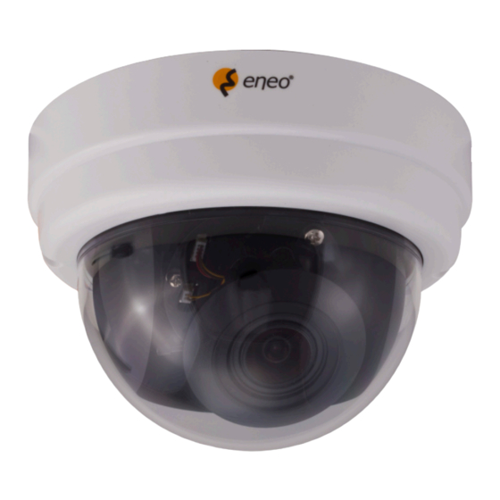
Summary of Contents for Eneo PXD-1110F39
- Page 1 Full Manual 1/2.7“ Full HD Network Dome Camera PXD-1110F39 PXD-1210Z03...
-
Page 2: Table Of Contents
Table of Contents Overview ..........................2 Features ........................2 Package Contents ....................... 3 Dimensions ........................4 Connectors ........................6 Camera Cabling ........................7 Connect Power ......................7 Connect Ethernet Cable....................7 Connect Alarm I/O ....................... 7 System Requirements ......................8 Access Camera ........................ -
Page 3: Overview
Overview The Full HD Multi-Streams Compact Dome IP Camera is a compact camera with an easy setup design. High Power PoE is supported to reduce complicated cabling without sacrificing performance. Moreover, 5 Megapixel Resolution is offered for providing high definition images. Quad Streams Compression (H.264 Baseline / Main / High Profile + MJPEG) are supported for efficient bandwidth and storage management. -
Page 4: Package Contents
Package Contents Please check the package contains the following items listed below. Full HD Multi-Streams Power Terminal Block Compact Dome IP Camera Self Tapping Screws (×2) Plastic Screw Anchors (×2) Quick Guide (bundled software and documentation) -
Page 5: Dimensions
Dimensions The dimensions of the IP Camera are shown below. -
Page 7: Connectors
Connectors The connectors of the IP Camera are shown in the below diagram. Definition for each connector is also given as follows. Connector Definition Remarks RJ-45 10/100 Mbps Ethernet / PoE AC 24_1 AC 24V AC 24_2 Power Power connection DC 12V DC 12V (+) For analog Video Output... -
Page 8: Camera Cabling
Camera Cabling Please follow the instructions below to complete IP Camera connection. Connect Power For power connection, please refer to the Connectors section of the previous chapter. Alternatively, connect the Ethernet Cable to the camera’s PoE port and plug the other end of the cable into a PoE switch. NOTE: If PoE is used, make sure Power Sourcing Equipment (PSE) is in used in the network. -
Page 9: System Requirements
System Requirements To perform the IP Camera via web browser, please ensure the PC is in good network connection, and meet system requirements as described below. Items System Requirement ® ® 1. Intel Pentium M, 2.16 GHz or ® Personal Computer Intel Core 2 Duo, 2.0 GHz... -
Page 10: Access Camera
Access Camera For initial access to the IP Camera, users can search the camera through the installer program: eneo Scan Device Tool, which can be found in “Scan Device Tool” folder in the supplied CD. For further information, please refer to the eneo Scan Device Tool Guide included in the same folder. -
Page 11: Setup Video Resolution
Setup Video Resolution Users can setup Video Resolution on Video Format page of the user-friendly browser-based configuration interface. Video Format can be found under this path: Streaming> Video Format. The default value of Video Resolution is as below. H.264- 1920 x 1080 (30 fps) + H.264- 720 x 480 (30 fps) For more Video Resolution combination details, please refer to chapter Appendix D: Video Resolution. -
Page 12: Configuration Files Export / Import
Configuration Files Export / Import To export / import configuration files, users can access the Maintenance page on the user-friendly browser-based configuration interface. The Maintenance setting can be found under this path: System> Maintenance. Users can export configuration files to a specified location and retrieve data by uploading an existing configuration file to the IP Camera. -
Page 13: Appendix A: Technical Specifications
Appendix A: Technical Specifications Camera PXD-1110F39 Image Sensor 1/2.7” Progressive CMOS Effective Pixels 1920 (H) x 1080 (V) Minimum Illumination 0.2 lux (Color) / 0.02 lux (B/W) Shutter Speed 1 ~ 1/10000 sec. Lens Lens Vari-focal Focal Length 3.0 ~ 9.0 mm F Number F1.2... - Page 14 Mechanical LED Indicator Power / Link / ACT Alarm 4 of 9 Pin Terminal Block Power 4 Pin Terminal Block Connectors Ethernet RJ-45 Analog Video 1.0 Vp-p / 75Ω, BNC Audio* 5 of 9 Pin Terminal Block General Operating Temperature Humidity ∅...
- Page 15 Camera PXD-1210Z03 Image Sensor 1/2.7” Progressive CMOS Effective Pixels 1920 (H) x 1080 (V) Shutter Speed 1 ~ 1/10000 sec. Lens Lens 3x Optical Zoom, Auto Focus 108º (Wide); 41º (Tele) Operation English / French / German / Italian / Japanese / Korean / Portuguese / Multiple Languages Russian / Simplified Chinese / Spanish / Traditional Chinese Iris Control*...
- Page 16 General Operating Temperature Humidity 10% ~ 90%, No Condensation ∅ 149 x 99.5 mm Weatherproof Standard* Dimension Weight Power Source DC 12V / AC 24V / PoE+ System Max. 5W Power Consumption 3x AF Max. 3W Regulatory CE / FCC / RoHS (*) Optional...
-
Page 17: Appendix B: Delete The Existing Dc Viewer
Appendix B: Delete the Existing DC Viewer For users who have installed the DC Viewer in the PC previously, please remove the existing DC Viewer from the PC before accessing to the IP Camera. Deleting the DC Viewer In the Windows <Start Menu>, activate <Control Panel>, and then double click on <Add or Remove Programs>. -
Page 18: Appendix C: Setup Internet Security
Appendix C: Setup Internet Security If ActiveX control installation is blocked, please either set Internet security level to default or change ActiveX controls and plug-ins settings. Internet Security Level: Default Step 1: Start the Internet Explorer (IE). Step 2: Click on the <Tools> tab on the menu bar and select <Internet Options>. Step 3: Click on the <Security>... -
Page 19: Appendix D: Video Resolution
Appendix D: Video Resolution Quad Streams H.264 + H.264 + H.264 + H.264 / MJPEG H.264-1 H.264-2 H.264-3 H.264-4 / MJPEG 720 x 480 (15 fps) 1280 x 720 (15 fps) 640 x 480 (15 fps) 352 x 240 (30 fps) 720 x 480 (30 fps) 800 x 600 (15 fps) 640 x 480 (30 fps) - Page 20 H.264 + H.264 + H.264 + H.264 / MJPEG H.264-1 H.264-2 H.264-3 H.264-4 / MJPEG 720 x 480 (30 fps) 1280 x 720 (15 fps) 640 x 480 (30 fps) 1280 x 720 (30 fps) 352 x 240 (30 fps) 720 x 480 (30 fps) 1280 x 1024 (15 fps) 800 x 600 (30 fps)
- Page 21 H.264 + H.264 + H.264 + H.264 / MJPEG H.264-1 H.264-2 H.264-3 H.264-4 / MJPEG 800 x 600 (30 fps) 352 x 240 (30 fps) 720 x 480 (30 fps) 352 x 240 (30 fps) 1280 x 720 (30 fps) 640 x 480 (30 fps) 352 x 240 (30 fps) 352 x 240 (30 fps)
- Page 22 H.264 + H.264 + H.264 + H.264 / MJPEG H.264-1 H.264-2 H.264-3 H.264-4 / MJPEG 800 x 600 (30 fps) 352 x 240 (30 fps) 720 x 480 (30 fps) 720 x 480 (30 fps) 640 x 480 (30 fps) 800 x 600 (30 fps) 352 x 240 (30 fps) 640 x 480 (30 fps)
-
Page 23: Triple Streams
Triple Streams H.264-1 + H.264-2 + H.264-3 / MJPEG H.264-1 H.264-2 H.264-3 / MJPEG 1280 x 720 (15 fps) 800 x 600 (30 fps) 1280 x 1024 (15 fps) 720 x 480 (30 fps) 640 x 480 (30 fps) 352 x 240 (30 fps) 1280 x 720 (30 fps) 1280 x 720 (15 fps) 800 x 600 (30 fps) - Page 24 H.264-1 + H.264-2 + H.264-3 / MJPEG H.264-1 H.264-2 H.264-3 / MJPEG 1280 x 720 (30 fps) 1280 x 1024 (15 fps) 800 x 600 (30 fps) 720 x 480 (30 fps) 1280 x 1024 (30 fps) 640 x 480 (30 fps) 352 x 240 (30 fps) 1280 x 1024 (15 fps) 1280 x 720 (15 fps)
- Page 25 H.264-1 + H.264-2 + H.264-3 / MJPEG H.264-1 H.264-2 H.264-3 / MJPEG 800 x 600 (30 fps) 720 x 480 (30 fps) 800 x 600 (30 fps) 640 x 480 (30 fps) 352 x 240 (30 fps) 720 x 480 (30 fps) 800 x 600 (30 fps) 720 x 480 (30 fps) 640 x 480 (30 fps)
-
Page 26: Dual Streams
Dual Streams H.264-1 + H.264-2 / MJPEG H.264-1 H.264-2 / MJPEG BNC SUPPORT 1920 x 1080 (15 fps) √ 1280 x 1024 (30 fps) 1920 x 1080 (15 fps) 1280 x 720 (30 fps) 1024 x 768 (30 fps) 800 x 600 (30 fps) 720 x 480 (30 fps) √... -
Page 27: Single Stream
Single Stream H.264 Only BNC SUPPORT 1920 x 1080 (30 fps) Low Latency* 1920 x 1080 (30 fps) √ 1280 x 1024 (30 fps) √ 1280 x 720 (30 fps) √ 1024 x 768 (30 fps) √ 800 x 600 (30 fps) √... - Page 28 Menu Tree Ver. 1.6...
- Page 29 Table of Contents Overview ..........................2 Menu Tree ..........................2 Home Page........................3 Streaming ........................44 Camera ........................51 Pan Tilt ........................57 Logout ........................60 Appendix A: Install UPnP Components..................61...
-
Page 30: Overview
Overview The IP Camera is provided with a user-friendly browser-based configuration interface, and a free bundled CMS (Central Management System) for video playback and recording. In this manual, information about main page introduction, system related settings and camera settings will be described in detail. -
Page 31: Home Page
Home Page Click on the tab <Home> to access the Home Page. There are several function buttons on the Home page. Detailed information of each item is as described in the following chapter. 2.1.1 Function Items on Home Page Multiple Languages Support Multiple languages are supported, including German, English, Spanish, French, Italian, Japanese, Korean, Portuguese, Russian, Simplified Chinese and Traditional Chinese for the viewer window interface. - Page 32 Video Streaming Pause / Restart button (pause / restart) Click on the <stop> button to disable video streaming, the live video will be displayed as black. Click on the <restart> button to show the live video again. Web Recording button (on / off) Click on the <Recording>...
- Page 33 Reset button Click on the <Reset> button, and the focus lens will first be reset to the maximum near end. Then the lens will be calibrated to a suitable position according to the monitoring environment. Push AF The one-push AF function is for fixing the focus in one click. Once clicked on the button, AF will be implemented.
- Page 34 System Under the tab <System>, there are submenus including: <System>, <Security>, <Network>, <DDNS>, <Mail>, <FTP>, <HTTP>, <Application>, <Motion Detection>, <Network Failure Detection>, <Tampering>, <Storage Management>, <Recording>, <Schedule>, <File Location>, <Fisheye Setting>, <Iris Adjustment>, <View Information>, <Factory Default>, <Software Version>, <Software Upgrade>...
- Page 35 Manual The Administrator can set video date, time and day manually. Entry format should be identical with that shown next to the enter fields. Sync with NTP server Network Time Protocol (NTP) is an alternate way to synchronize the camera’s clock with a NTP server.
- Page 36 I/O access This item supports fundamental functions that enable users to view video when accessing to the camera. Camera control This item allows the appointed User to change camera parameters on the Camera Setting page. Talk / Listen ...
- Page 37 2.2.2.2 HTTPS The HTTPS setting can be found under this path: System> Security> HTTPS. <HTTPS> allows secure connections between the IP Camera and web browser using <Secure Socket Layer (SSL)> or <Transport Layer Security (TLS)>, which ensure camera settings or Username / Password info from snooping. It is required to install a self-signed certificate or a CA-signed certificate for implementing <HTTPS>.
- Page 38 Provide the Certificate Information To create a Self-signed HTTPS Certificate or a Certificate Request to CA, please enter the information as requested: Create Self Signed Certificate Create Certificate Request √ √ Country √ √ State or Province √ √ Locality √...
- Page 39 2.2.2.3 IP Filter The IP Filter setting can be found under this path: System> Security> IP Filter. Using the IP filter, access to the IP Camera can be restricted by denying / allowing specific IP addresses. Enable IP Filter Check the box to enable the IP Filter function.
- Page 40 2.2.2.4 IEEE 802.1X The IEEE 802.1X setting can be found under this path: System> Security> IEEE 802.1X. The IP Camera is allowed to access a network protected by 802.1X/EAPOL (Extensible Authentication Protocol over LAN). Users need to contact with the network administrator for gaining certificates, user IDs and passwords CA Certificate The CA certificate is created by the Certification Authority for the purpose of...
- Page 41 2.2.3 Network The Network setting can be found under this path: System> Network. Click on the <Network> category, there will be a drop-down menu with tabs including <Basic>, <QoS>, <SNMP> and <UPnP>. 2.2.3.1 Basic The Basic setting can be found under this path: System> Network> Basic. Users can choose to connect to the IP Camera with fixed or dynamic (DHCP) IP address.
- Page 42 IP address This is necessary for network identification. Subnet mask It is used to determine if the destination is in the same subnet. The default value is “255.255.255.0”. Default gateway This is the gateway used to forward frames to destinations in different subnet.
- Page 43 HTTPS port The default setting of HTTPS Port is 443; the setting range is from 1024 to 65535. NOTE: Be aware to choose the different port from the one set for the web server port. IPv6 Address Configuration With IPv6 support, users can use the corresponding IPv6 address for browsing. Enable IPv6 by checking the box and click on <Save>...
- Page 44 2.2.3.3 SNMP The SNMP (Simple Network Management Protocol) setting can be found under this path: System> Network> SNMP. With Simple Network Management Protocol (SNMP) support, the IP Camera can be monitored and managed remotely by the network management system. SNMP v1 / v2 Enable SNMP v1 / v2 ...
- Page 45 2.2.3.4 UPnP The UPnP setting can be found under this path: System> Network> UPnP. UPnP Setting Enable UPnP When the UPnP is enabled, whenever the IP Camera is presented to the LAN, the icon of the connected IP Cameras will appear in My Network Places to allow for direct access.
- Page 46 2.2.4 DDNS The DDNS setting can be found under this path: System> DDNS. Dynamic Domain Name System (DDNS) allows a host name to be constantly synchronized with a dynamic IP address. In other words, it allows those using a dynamic IP address to be associated to a static domain name so others can connect to it by name.
- Page 47 2.2.6 The FTP setting can be found under this path: System> FTP. The Administrator can set as sending alarm message to a specific File Transfer Protocol (FTP) site when event is triggered. Users can assign alarm message to up to two FTP sites. Enter the FTP details, which include server, server port, user name, password and remote folder, in the fields.
- Page 48 2.2.8 Application (Compact Fixed Dome Excluded) The Application setting can be found under this path: System> Application. The IP Camera equips one alarm input and one relay output for cooperating with alarm system to catch events’ images. Refer to alarm pin definition below to connect alarm devices to the IP Camera if needed.
- Page 49 Send Message by FTP/E-Mail The Administrator can select whether to send an alarm message by FTP and/or E-Mail when an alarm is triggered. Upload Image by FTP Select this item and the Administrator can assign a FTP site and configure various parameters.
- Page 50 Check the box <Continue image upload> to upload the triggered images during certain time or keep uploading until the trigger is off. Select <Upload for __sec> and enter the duration in the blank. The images of the duration will be uploading by E-mail when the alarm input is triggered.
- Page 51 File Name Enter a file name in the blank, ex. image.jpg. The uploaded image’s file name format can be set in this section. Please select the one that meets the requirements. Add date/time suffix File name: imageYYMMDD_HHNNSS_XX.jpg Y: Year, M: Month, D: Day H: Hour, N: Minute, S: Second X: Sequence Number Add sequence number suffix (no maximum value)
-
Page 52: Motion Detection
2.2.9 Motion Detection The Motion Detection setting can be found under this path: System> Motion Detection. Motion Detection function allows detecting suspicious motion and triggering alarms when motion volume in the detected area reaches / exceeds the determined sensitivity threshold value. The function supports up to 4 sets of Motion Detection Settings. - Page 53 When motion is detected, the signals will be displayed on the Motion window as shown below. Motion Detection In each set of Motion Detection Setting, the default setting for the Motion Detection function is <Off>. Enable the function by selecting <On>. Users can also activate the function according to the schedule previously set in the <Schedule>...
- Page 54 Sensitivity level [1-100]: The default level is 80, which means if 20% or more sampling pixels are detected differently, system will detect motion. The bigger the value, the more sensitive it is. Meanwhile, when the value is bigger, the red horizontal line in the motion indication window will be lower accordingly.
- Page 55 Upload Image by FTP Select this item and the Administrator can assign a FTP site and configure various parameters. When motion is detected, event images will be uploaded to the appointed FTP site. <Pre-trigger buffer> function allows users to check what happened to cause the trigger.
- Page 56 The setting range is from 1 to 9999 seconds. Select <Upload during the trigger active> to make the images keep being uploaded to E-mail during the trigger active until the event stops. Set the Image frequency as the upload frame rate. The setting range is from 1 frame to 15 frames.
-
Page 57: Network Failure Detection
Add sequence number suffix up to # and then start over File Name: imageXX.jpg X: Sequence Number The file name suffix will end at the number being set. For example, if the setting is up to “10,” the file name will start from 00, end at 10, and then start all over again. - Page 58 Triggered Action (Multi-option) The Administrator can specify alarm actions that will take when network failure is detected. All options are listed as follows: Enable Alarm Output Select the item to enable alarm relay output. Record Stream to SD Card ...
- Page 59 2.2.11 Tampering The Tampering setting can be found under this path: System> Tampering. Tampering Alarm function helps the IP Camera against tampering such as deliberate redirection, blocking, paint spray, and lens cover, etc through video analysis and reaction to such events by sending out notifications or uploading snapshots to the specified destination(s).
- Page 60 Record stream to SD Card Select this item and the Tampering Alarm recording will be stored in Micro SD / SDHC card when tampering is detected. Pre-trigger buffer recording function allows users to check what happened to cause the trigger. The pre-trigger buffer time range is from 1 to 3 seconds.
- Page 61 Check the box <Continue image upload> to upload the triggered images during certain time or keep uploading until the trigger is off. Select <Upload for __sec> and enter the duration in the blank. The images of the duration will be uploaded to FTP when tampering is triggered. The setting range is from 1 to 9999 seconds.
- Page 62 Send HTTP notification Check this item, select the destination HTTP address, and specify the parameters for HTTP notifications. When the Tampering Alarm is triggered, the HTTP notifications can be sent to the specified HTTP server. For instance, if the custom parameter is set as” action=1&group=2”, and the HTTP server name is ”http://192.168.0.1/admin.php”, the notification will be sent to HTTP server as ”http://192.168.0.1/admin.php?
- Page 63 Save Click the <Save> button to save all the Tampering Alarm settings mentioned above. 2.2.12 Storage Management (Local Recording) The Storage Management setting can be found under this path: System> Storage Management. Users can implement local recording to the Micro SD / SDHC card up to 32GB. This page shows the capacity information of the Micro SD card and a recording list with all the recording files saved on the memory card.
- Page 64 Recording List Each video file on the Micro SD / SDHC card will be listed in the Recording list as shown below. The maximum file size is 60 MB (60 MB per file). When the recording mode is set as “Always” (consecutive recording) and the Micro SD / SDHC card recording is also allowed to be enabled by events triggered, once events occur, the system will immediately implement events recording to the memory card.
- Page 65 2.2.13 Recording (Local Recording) The Recording setting can be found under this path: System> Recording. In the Recording setting page, the Micro SD Card recording schedule supports up to ten sets of time frames. User can specify the recording schedule to fit the present surveillance requirement.
- Page 66 2.2.14 Schedule The Schedule setting can be found under this path: System> Schedule. This function allows the users to setup schedules for features including: <Alarm Switch>, <Motion Detection>, <Network Failure Detection> and <Tampering>. The function supports up to 10 sets of time frames in the time frame list. Setting Schedules To set a schedule, please select a time frame from the time frame list first.
- Page 67 2.2.15 File Location (Snapshots and Web Recording) The File Location setting can be found under this path: System> File Location. Users can specify a storage location on the PC or in the hard drive for the snapshots and live video recording. The default setting is: C:\. Once confirm the setting, click on <Save>, and all the snapshots and web recording will be saved in the designate location.
-
Page 68: Iris Adjustment
2.2.16 Iris Adjustment The Iris Adjustment function can be found under this path: System> Iris Adjustment. For users who use Auto-iris lens, when it is required to implement iris adjustment, please refer to the Iris adjustment procedure in the setting page to adjust iris. -
Page 69: Factory Default
Get User Privacy Click on <get user privacy> at the bottom of the page, and the Administrator can view each user’s privileges as shown below: User: 1:1:0:1 1:1:0:1= I/O access : Camera control : Talk : Listen (refer to Security) Therefore, it denotes the user is granted privileges of I/O access, Camera control and Listen. -
Page 70: Software Version
2.2.19 Software Version The Software Version can be found under this path: System> Software Version. The current software version is displayed in the software version page. 2.2.20 Software Upgrade The Software Upgrade setting can be found under this path: System> Software Upgrade. - Page 71 Step 6. Open a new web browser, re-login the IP Camera, and then allow the automatic download of DC Viewer. Step 7. 2.2.21 Maintenance The Maintenance setting can be found under this path: System> Maintenance. Users can export configuration files to a specified location and retrieve data by uploading an existing configuration file to the IP Camera.
-
Page 72: Streaming
Streaming Under the tab <Streaming>, there are submenus including: <Video Format>, <Video Compression>, <Video ROI>, <Video OCX Protocol>, <Video Frame Rate>, <Video Mask> and <Audio>. In the Streaming submenus, the Administrator can configure specific video resolution, video compression mode, video protocol, audio transmission mode, etc. - Page 73 90 Degree counter-/clockwise Selecting <90 Degree Counter-/clockwise> will make the image 90° counter-/clockwise inversed. 180 Degree Rotate Selecting <180 Degree> will make the image 180° inversed. Click on <Save> to confirm the setting. GOV Settings Users can set the GOV length to determine the frame structure (I-frames and P-frames) in a video stream for saving bandwidth.
-
Page 74: Video Compression
2.3.2 Video Compression The Video Compression setting can be found under this path: Streaming> Video Compression. Users can select a proper MJPEG / H.264 compression mode in the video compression page depending on the application. MJPEG Q (Quality) factor Higher value implies higher bit rates and higher visual quality. The default setting of MJPEG Q factor is 35;... -
Page 75: Video Roi
2.3.3 Video ROI The Video ROI setting can be found under this path: Streaming> Video ROI. ROI stands for Region of Interest. This function allows users to select specific monitoring region for H.264-2, H.264-3, H.264-4 and MJPEG streams, instead of showing the full image. NOTE: This function is only available when triple streams or above is selected under <Video Resolution>... -
Page 76: Video Ocx Protocol
Enable MJPEG ROI Setting Check the box and MJPEG ROI Window will be displayed. To change the size of MJPEG ROI Window, move the mouse cursor to the edge of the frame and draw it outward / inward. Moving the mouse to the center of the frame can shift the frame to the intended location. -
Page 77: Video Frame Rate
2.3.5 Video Frame Rate The Video Frame Rate setting can be found under this path: Streaming> Video Frame Rate. Video frame rate is for setting the frames per second (fps) if necessary. MJPEG / H.264-1 / H.264-2 / H.264-3 / H.264-4 Frame Rate The default setting of MJPEG / H.264-1 / H.264-2 / H.264-3 / H.264-4 Frame Rate is 30 fps;... - Page 78 2.3.7 Audio (Audio Mode and Bit Rate Settings) The Audio Mode setting can be found under this path: Streaming> Audio. In the Audio page, the Administrator can select one transmission mode and audio bit rate. Transmission Mode Full-duplex (Talk and Listen simultaneously) ...
-
Page 79: Camera
Recording to Storage Select <Enable> from the drop-down menu to enable recording audio with video into SD card. NOTE: If the chosen bit rate is not compatible with the player, there will be no audio and noise will be heard during playback. Camera Under the tab <Camera>, there are submenus including: <Exposure>, <White Balance>, <Picture Adjustment>, <Backlight>, <Digital Zoom>, <IR Function>,... - Page 80 P-Iris Priority Mode Select <Auto Detect>, the camera will automatically detect the best iris size for the environment. Users can manually adjust the iris size by selecting <Manual>. Adjust the iris size by clicking . The minimum shutter speed can be set from 1 (1/1.5) to 1/30 (1/25) sec.
-
Page 81: White Balance
Manual Mode With this mode, users can select the suitable shutter speed and iris size according to the environmental illumination. The shutter speed range is from 1/10000 to 1 (1/1.5) sec. with 19 (18) options. The range of the iris size is from 0 to 9, or selects <Full open>... -
Page 82: Picture Adjustment
Manual Mode In this mode, users can change the White Balance value manually. Users can select a number between 0 ~127 of “Rgain / Bgain” item to gain the red / blue illuminant on the Live Video Pane. 2.4.3 Picture Adjustment The Picture Adjustment can be found under this path: Camera>... -
Page 83: Digital Zoom
2.4.4 Backlight The Backlight Setting can be found under this path: Camera> Backlight. The Backlight Compensation function prevents the center object from being too dark in surroundings where excessive light is behind the center object. Click on < √ > to confirm the new setting. 2.4.5 Digital Zoom The Digital Zoom Setting can be found under this path: Camera>... - Page 84 environment. The combination of SPQ and 3DNR at different level further yields exceptional video performance in various conditions. The Noise Reduction function is configurable with the following options: 3DNR Low, 3DNR Mid, 3DNR Hi, SPQ, SPQ + 3DNR Low, SPQ + 3DNR Mid, to SPQ + 3DNR Hi.
-
Page 85: Pan Tilt
Pan Tilt Under the tab <Pan Tilt>, there are submenus including: <Preset>, <Sequence> and <Pan/Tilt Control>. NOTE: Pan Tilt function is only available for Zoom Camera and Box Camera (DC12V / AC24V / PoE Model). With RS-485 support, the IP Camera is capable of working with a Pan Tilt Head for pan and tilt control. - Page 86 Preset Run Type the Preset Point number into the Preset field, click on the button, and the camera will turn to the appointed point. 2.5.2 Sequence The Sequence Setting can be found under this path: Pan Tilt> Sequence. The Sequence function supports totally eight Sequence Lines; each Sequence Line consists of up to 64 Preset Points.
- Page 87 Sequence Run Select the specified Sequence Line from the drop-down list, click on the button, and then the camera will start moving forward each scene sequentially as programmed. To view the camera executing a Sequence Line in full screen mode, please move the cursor onto the live view pane, right-click and left-click to select “fullscreen”.
-
Page 88: Logout
Logout Click on the tab <Logout> on the top of the page, and the login window will pop up. This enables log in with another user name. -
Page 89: Appendix A: Install Upnp Components
Appendix A: Install UPnP Components Please follow the instructions below to install UPnP components on Windows Vista / Windows XP / Windows 7. Step1: In the Windows, go to <Start Menu>, click on <Control Panel>, and then double click on <Add or Remove Programs>. Step 2: Click on <Add / Remove Windows Components>... - Page 90 Videor E. Hartig GmbH Exclusive distribution through specialised trade chan- nels only. Videor E. Hartig GmbH Carl-Zeiss-Straße 8 · 63322 Rödermark/Germany Tel. +49 (0) 6074 / 888-0 · Fax +49 (0) 6074 / 888- Technical changes reserved www.videor.com...
Need help?
Do you have a question about the PXD-1110F39 and is the answer not in the manual?
Questions and answers