Table of Contents
Advertisement
Quick Links
Advertisement
Chapters
Table of Contents

Related Manuals for Eneo PXD-2018PTZ1080


Summary of Contents for Eneo PXD-2018PTZ1080
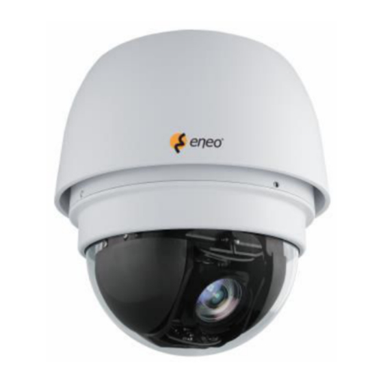
- Page 1 1/2.8” Network Full HD Speed Dome, PTZ, 18x, Day&Night PXD-2018PTZ1080...
- Page 2 Installation Guide Contents Part 1 – Installation Guide ................3 Part 2 – User Manual .................. 35 Part 3 – Menu Tree ..................53...
-
Page 3: Part 1 – Installation Guide
Installation Guide Part 1 Installation Guide Version 1.2... - Page 4 Installation Guide Preface Information given in this manual was current when published. The company reserves the right to revise and improve its products. All specifications are subject to change without notice. Notice This manual provides installation information for the outdoor Integrated High Speed Dome Camera.
- Page 5 Installation Guide Regulation This device complies with Part 15 of the FCC Rules. Operation is subject to the following two conditions: (1) this device may not cause harmful interference, and (2) this device must accept any interference received, including interference that may cause undesired operation. This symbol on the product or on its packaging indicates that this product shall not be treated as household waste in accordance with Directive 2002/96/EC.
-
Page 6: Safety Instructions
Installation Guide Safety Instructions • Read these safety instructions and the operation manual first before you install and commission the camera. • Keep the manual in a safe place for later reference. • Protect your camera from contamination with water and humidity to prevent it from permanent damage. -
Page 7: Table Of Contents
Installation Guide Table of Contents – Part 1 Introduction .......................... 8 Standard Package Contents ....................9 Camera Cable Connections ..................... 10 Switch/Connector Definition .................. 10 Cable Requirements ....................11 3.2.1 Power Connection ..................11 3.2.2 Ethernet Cable Connection ............... 11 Dome Camera Installation .................... -
Page 8: Introduction
Installation Guide Introduction The Full HD Speed Dome IP Camera is designed to deliver superb performance and durability with an intelligent and stylish housing that is suitable in any security and surveillance installation. -
Page 9: Standard Package Contents
Installation Guide Standard Package Contents Before proceeding, please check the box contains the items listed here. If any item is missing or has defects, DO NOT install or operate the product and contact your dealer for assistance. Outdoor Model M3 Standard Screw (x1) M3 Security Screw (x1)* M5 Standard Screw (x1) M5 Security Screw (x1)*... -
Page 10: Camera Cable Connections
Installation Guide Camera Cable Connections Before installing or connecting the Dome Camera, please refer to this section and complete preparations for dome setups and various switch settings. There will be a PE cloth sheet covered inside the dome cover and a lens cap on the lens for shipping protection. -
Page 11: Cable Requirements
Installation Guide Cable Requirements For operation, the network Speed Dome IP Camera require power cable and RJ-45 as described below: 3.2.1 Power Connection Please refer to the illustrations below to connect power core through the supplied power adaptor. Definition AC 24- AC 24+ 3.2.2 Ethernet Cable Connection... -
Page 12: Dome Camera Installation
Installation Guide Dome Camera Installation Basing on user’s installation environments, the Dome Camera can be installed on ceiling, on wall or on pole. In the following section, various Dome Camera’s installation accessories, installation methods and installation procedures will be described in detail. In addition, the next section will provide the Dome Camera’s dimensions for your reference before installation. -
Page 13: Optional Accessories
Installation Guide Optional Accessories Dome Camera Accessories Transparent/Vandal Proof Transparent Cover (Standard) Vandal Proof Cover (Optional) Mounting Accessories Standard Pendent Mount (Art. No. 200825) White; 348×104×138.6 mm (13.7×4.1×5.5 inches); 1.5 kg (3.3 lbs); Diameter: 45 mm (1.8 inches). Supplied with M8x12 screw x1, spring washer-8 x1, pendent tube washer x1, rubber washer-8 x1 and sponge x2. - Page 14 Installation Guide Compact Pendent Mount (Art. No. 200826) 184×104×127 mm (7.24×4.09×5 inches); 0.6 kg (1.2 lbs) Supplied with rubber washer-8 x1, pendent tube washer x1, spring washer-8 x1 and M8x12 screw x1. Dimensions: mm Straight Tube (Art. No. 200827) Iron, Height: 250 mm (9.8 inches) ,Diameter: 50 mm (2 inches) 1 kg (2.2 lbs), Supplied with M8x12 screw x1, spring washer-8 x1, pendent tube washer x1, rubber washer-8 x1 and waterproof rubber x1.
- Page 15 Installation Guide Corner Plate Mini (Art. No. 200831) For mounting with Compact Pendent Mount. 200(L)×90(H)×117(D) mm (7.87×3.54×4.6 inches); Supplied with washer-8 x4, spring washer-8 x4, M8x16 screw x4 and M8 nut x4. Dimensions: mm Corner Standard Mounting Plate (Art. No. 200830) 204(L)×222(H)×117(D) mm (8×8.74×4.6 inches);...
- Page 16 Installation Guide Pole Thin Direct Mounting (Art. No. 200834) 232(H)×136(W)×50(D) mm (9.1×5.4×2 inches); Diameter: 112~130 mm (4.4~5 inches); 0.7 kg (1.6 lbs). Supplied with stainless steel straps x4, M8x16 screw x4, washer x4 and spring washer-8 x4. Dimensions: mm Corner Wide Box Mounting (Art. No. 200832) 232(H)×234(W)×208(D) mm (9.1×9.2×8.2 inches);...
- Page 17 Installation Guide Pole Wide Box Mounting (Art. No. 200835) 270(H)×170(W)×155(D) mm (10.6×6.7×6.1 inches); 3.2 kg (7.1 lbs); Supplied with M8x16 screw x4, washer-8 x4, spring washer-8 x4 and stainless steel straps x4. Power Box can be set inside the wide box. Dimensions: mm Wall Box Mounting (Art.
- Page 18 Installation Guide Stainless Steel Straps For fixing Pole Direct Mounting / Pole Box on the pole. Length: 650 mm (25.6 inches); Width: 12.7mm; Weight: 50g (0.1 lb) All photos of the accessories are subject to change without notice.
-
Page 19: Ceiling Mounting With Straight Tube
Installation Guide Ceiling Mounting with Straight Tube The Straight Tube is available in different length: 25 cm and 50 cm. Package Contents: M8x12 Screw x1 Spring Washer-8 x1 Pendent Tube Washer x1 Rubber Washer-8 x1 Waterproof Rubber x1 Items Needed: Dome Camera... - Page 20 Installation Guide Mount the Dome Camera to the Mounting Kit. (Ensure the Dome Camera is fixed completely, and the thread holes on the Lock Screw Plate and Mounting Kit are aligned). Afterwards, screw the supplied M5 standard screw / security screw, as shown in the picture. Ceiling Mounting: Straight Tube...
-
Page 21: Wall Mount
Installation Guide Wall Mount The Dome Camera can be mounted on the wall with Compact Pendent Mount, Standard Pendent Mount and Wall Box. Please follow the installation instructions below for mounting the Dome Camera via different ways. 4.4.1 Compact Pendent Mount Package Contents: ... - Page 22 Installation Guide 2) Fix the Compact Pendent Mount on the wall with proper screws and screw anchors. 3) Attach the Waterproof Rubber to the Compact Pendent Mount. 4) Run the cable(s) through the Compact Pendent Mount with the Data Cable’s 22-pin cable coming out of the outlet.
-
Page 23: Standard Pendent Mount
Installation Guide 4.4.2 Standard Pendent Mount Package Contents: M8x12 Screw x1 Spring Washer-8 x1 Pendent Tube Washer x1 Rubber Washer-8 x1 Sponge x2 Items Needed: Dome Camera Power Cable Ethernet Cable Standard Pendent Mount and equipped items (optional accessory) ... - Page 24 Installation Guide 5) Thread the cable(s) through the Outdoor Mount Kit and join the Outdoor Mount Kit to the Standard Pendent Mount with the supplied screws and washers. Then adjust the Waterproof Rubber to the joint. 6) Connect the cable(s) to the Dome Camera. 7) Join the Dome Camera to the Mounting Kit with the supplied screw and washers.
-
Page 25: Wall Box Mounting
Installation Guide 4.4.3 Wall Box Mounting Package Contents: M8x16 Screw x4 Washer-8 x4 Spring Washer-8 x4 Items Needed: Dome Camera Power Cable Ethernet Cable Standard/Compact Pendent Mount and equipped items (optional accessory) Wall Box Mounting (optional accessory) ... - Page 26 Installation Guide 5) Thread the cable(s) through the Outdoor Mount Kit and join the Mounting Kit to the Standard/Compact Pendent Mount with the supplied screws and washers. Then adjust the Waterproof Rubber to the joint. 6) Connect the cable(s) to the Dome Camera. 7) Join the Dome Camera to the Mounting Kit with the supplied screw and washers.
-
Page 27: Corner Mount
Installation Guide Corner Mount 4.5.1 Corner Standard Mounting Plate/Corner Plate Mini Package Contents: Washer-8 x4 Spring Washer-8 ×4 M8x16 Screw x4 M8 Nut x4 Items Needed: Dome Camera Power Cable Ethernet Cable Standard/Compact Pendent Mount and equipped items (optional accessory) ... - Page 28 Installation Guide 4) Attach the Waterproof Rubber to the Standard/Compact Pendent Mount. 5) Thread the cable(s) through the Mounting Kit and join the Mounting Kit to the Standard/Compact Pendent Mount with the supplied screws and washers. Then adjust the Waterproof Rubber to the joint. 6) Connect the cable(s) to the Dome Camera.
-
Page 29: Corner Thin/Wide Box Mounting
Installation Guide 4.5.2 Corner Thin/Wide Box Mounting Package Contents: M8x16 Screw x4 Washer-8 x4 Spring Washer-8 x4 Items Needed: Dome Camera Power Cable Ethernet Cable Standard/Compact Pendent Mount and equipped items (optional accessory) ... - Page 30 Installation Guide 5) Thread the cable(s) through the Mounting Kit and join the Mounting Kit to the Standard/Compact Pendent Mount with the supplied screws and washers. Then adjust the Waterproof Rubber to the joint. 6) Connect the cable(s) to the Dome Camera. 7) Join the Dome Camera to the Mounting Kit with the supplied screw and washers.
-
Page 31: Pole Mount
Installation Guide Pole Mount 4.6.1 Pole Thin/Wide Direct Mounting Package Contents: M8x16 Screw x4 Washer x4 Stainless Steel Straps x4 Spring Washer-8 x4 Items Needed: Dome Camera Power Cable Ethernet Cable Standard/Compact Pendent Mount and equipped items (optional accessory) ... - Page 32 Installation Guide 5) Thread the cable(s) through the Mounting Kit and join the Mounting Kit to the Standard/Compact Pendent Mount with the supplied screws and washers. Then adjust the Waterproof Rubber to the joint. 6) Connect the cable(s) to the Dome Camera. 7) Join the Dome Camera to the Mounting Kit with the supplied screw and washers.
-
Page 33: Pole Thin/Wide Box Mounting
Installation Guide 4.6.2 Pole Thin/Wide Box Mounting Package Contents: M8x16 Screw x4 Washer-8 x4 Spring Washer x4, Stainless Steel Straps x4 Items Needed: Dome Camera Power Cable Ethernet Cable Standard/Compact Pendent Mount and equipped items (optional accessory) ... - Page 34 Installation Guide 5) Thread the cable(s) through the Mounting Kit and join the Mounting Kit to the Standard/Compact Pendent Mount with the supplied screws and washers. Then adjust the Waterproof Rubber to the joint. 6) Connect the cable(s) to the Dome Camera. 7) Join the Dome Camera to the Mounting Kit with the supplied screw and washers.
-
Page 35: Part 2 – User Manual
User Manual Part 2 User Manual Version 1.4... - Page 36 User Manual Table of Contents – Part 2 Overview ........................... 37 Features ......................... 37 Package Contents ....................38 Switch/Connector Definition ..................39 Camera Cabling ........................ 40 Connect Power ......................40 Connect Ethernet Cable .................... 40 Apply Alarm I/O ......................41 Apply Audio .......................
-
Page 37: Overview
User Manual Overview The Full HD Speed Dome IP Camera transmits digital video and audio data using wire connection. Live video can be monitored and recorded from window-based computer via network. The video encoder supports real-time Main Profile H.264 Full HD resolution. Simultaneous dual streams, H.264/H.264 and H.264/MJPEG, are available for various network applications via speeding or limited bandwidth. -
Page 38: Package Contents
User Manual Package Contents Please check the box contains the items listed here. If any item is missing or has defects, DO NOT install or operate the product and contact your dealer for assistance. Outdoor Dome Camera Package M3 Standard Screw (x1) M3 Security Screw (x1)* M5 Standard Screw (x1) M5 Security Screw (x1)*... -
Page 39: Switch/Connector Definition
User Manual Switch/Connector Definition There are various switches and connectors located on the Dome Camera’s back plate as shown in the figures below. Please refer to the diagram and table accompanied with for use of each switch/connector. Outdoor Model RJ-45 Connector ALARM I/O Power Micro SD Card Slot... -
Page 40: Camera Cabling
User Manual Camera Cabling Please follow the instructions below to complete network Speed Dome Camera connection. Connect Power Please refer to the illustrations below to connect power core through the supplied power adaptor. Definition AC 24_1 AC 24_2 Connect Ethernet Cable Use of Category 5 Ethernet cable is recommended for network connection;... -
Page 41: Apply Alarm I/O
User Manual Apply Alarm I/O The network Speed Dome Camera supports 4 digital alarm inputs and 2 digital alarm outputs. Please make sure the alarm connections are properly wired before starting to configure alarm related settings on this “Application” page. Please refer to the pin definition table below for alarm system wiring. -
Page 42: System Requirements
User Manual System Requirements To perform the network Speed Dome Camera via web browser, please ensure your PC is in good network connection, and meet system requirement as described below. Items Minimum Requirement ® ® ® 1. Intel Pentium IV, 3 GHz or higher, Intel Core2 Duo, 2 GHz or higher Personal Computer... -
Page 43: Camera Login
User Manual Camera Login The network Speed Dome Camera’s default IP address is: 192.168.1.10. Therefore, to access the camera for the first time, set the PC’s IP address as: 192.168.1.XXX; for example: IP Address: 192.168.1.20 Subnet Mask: 255.255.255.0 Login ID & Password ... -
Page 44: Setup Video Resolution
User Manual Setup Video Resolution Users can setup Video Resolution on Video Format page of the user-friendly browser-based configuration interface. Video Format can be found under this path: Streaming> Video Format. -
Page 45: Video Format
User Manual Video Format Under Video Resolution section, select a preferred resolution setting. The available Video Resolution for MJPEG & H.264 format includes: MJPEG+ H.264 MJPEG H.264 BNC SUPPORT √ 720 x 480 (30fps)* √ 1920 x 1080 (30fps) 640 x 480 (30fps) √... - Page 46 User Manual √ 640 x 480 (30fps) 640 x 480 (30fps) √ 352 x 240 (30fps) H.264 + H.264 H.264-1 H.264-2 BNC SUPPORT √ 720 x 480 (30fps)* √ 1920 x 1080 (30fps) 640 x 480 (30fps) √ 352 x 240 (30fps) √...
- Page 47 User Manual √ 640 x 480 (30fps) 640 x 480 (30fps) √ 352 x 240 (30fps) MJPEG ONLY MJPEG BNC SUPPORT √ 1920 x 1080 (30fps) √ 1280 x 1024 (30fps) √ 1280 x 720 (30fps) √ 1024 x 768 (30fps) √...
-
Page 48: Appendix A: Technical Specifications
User Manual Appendix A: Technical Specifications Type PXD-2018PTZ1080 Art. No. 200824 Resolution standard HD 1080p System True Day&Night Sensor size 1/2.8" Imager CMOS Sony Progressive Scan Sensitivity (at 50% video 0.1Lux (colour); 0.03Lux (B&W) signal) Automatic gain control (AGC) supplied Automatic electronic shutter 1/25 ~ 1/10,000sec. - Page 49 User Manual Audio 1/1 Line input and output Alarm inputs Alarm output SD-card recording, alarm out, FTP, E-Mail, PTZ Alarm processing action Internal storage Micro SD card / SD HC 32GB Compression standard H.264, MJPEG Audio standards G.711, G.726, ADPCM/AAC Bandwidth controllable bandwidth and frame rate H.264, MJPEG multiple...
- Page 50 Vandalism resistant outdoor Housing Housing material metal / plastic Colour (housing) RAL 9003 Colour (bubble) clear IP66 Protection rating Management Software Support www.eneo-security.com/software available ONVIF Certificates CE, IK10 Dimensions see drawing (P. 12) 2.4kg Weight screw set, manual Parts supplied...
-
Page 51: Appendix B: Delete The Existing Dc Viewer
User Manual Appendix B: Delete the Existing DC Viewer For users who have installed the DC Viewer in the PC previously, please first remove the existing DC Viewer from the PC before accessing to the network Speed Dome Camera. Deleting the DC Viewer Activate <Control Panel>, and then double click on <Add or Remove Programs>. -
Page 52: Appendix C: Setup Internet Security
User Manual Appendix C: Setup Internet Security If ActiveX control installation is blocked, please either set Internet security level to default or change ActiveX controls and plug-ins settings. Internet Security Level: Default Step 1: Start the Internet Explorer (IE). Step 2: Click on the <Tools> tab on the menu bar and select <Internet Options>. Step 3: Click on the <Security>... -
Page 53: Part 3 – Menu Tree
Menu Tree Part 3 Menu Tree Version 1.2... -
Page 54: Table Of Contents – Part
Menu Tree Table of Contents – Part 3 Overview ..........................56 Menu Tree ........................... 56 Home Page ....................... 57 2.1.1 Function Items on Home Page ..............57 System ........................60 2.2.1 System ....................... 60 2.2.2 Security ...................... 61 2.2.3 Network ...................... 66 2.2.4 DDNS ...................... - Page 55 Menu Tree 2.4.2 Cruise ......................92 2.4.3 Auto Pan ....................93 2.4.4 Sequence ....................94 2.4.5 Home ......................95 2.4.6 Tilt Range ....................96 2.4.7 Camera— Exposure ................... 96 2.4.8 Camera—WB (White Balance) ..............97 2.4.9 Camera—Misc 1 (Miscellaneous Setups Menu 1) ........97 2.4.10 Camera—Misc 2 (Miscellaneous Setups Menu 2) ........
-
Page 56: Overview
Menu Tree Overview The Full HD Speed Dome IP Camera transmits digital video and audio data using wire connection. Live video can be monitored and recorded from window-based computer via network. The video encoder supports real-time Main Profile H.264 Full HD resolution. Simultaneous dual streams, H.264/H.264 and H.264/MJPEG, are available for various network applications via speeding or limited bandwidth. -
Page 57: Home Page
Menu Tree Logout Click on the tab to re-login the IP Camera with another username and password. Home Page Click on the tab <Home> to access the Home Page. There are several function buttons on the Home pate. Detailed information of each item is as described in the following chapter. - Page 58 Menu Tree Video Streaming Pause /Restart button (pause/restart) Click on the <Stop> button to disable video streaming, the live video will be displayed as black. Press the <restart> button to show the live video again. Web Recording button (on/off) Click on the <Recording> button and the Live View through the web browsing will be directly recorded to the specific location on the local hard drive, which could be configured in the <File Location>...
- Page 59 Menu Tree Optical/Digital Zoom Control In Normal View display mode, users can implement zoom in/out by first moving the cursor to the live video pane and then rotating the mouse wheel. As in Full Screen mode, users can directly rotate the mouse wheel to zoom in/out on the image.
-
Page 60: System
Menu Tree System Under the tab <System>, there are categories as the table below: System Security Network DDNS Mail HTTP Application Motion Detection Tampering System Storage Management Recording File Location View Log File View User Information View Parameters Factory Default Software Version Software Upgrade Maintenance... -
Page 61: Security
Menu Tree Sync With Computer Time Select the item and video date and time display will synchronize with the PC’s. Manual The Administrator can set video date, time and day manually. Entry format should be identical with that shown next to the enter field. Sync with NTP Server Network Time Protocol (NTP) is an alternate way to synchronize your camera’s clock with a NTP server. - Page 62 Menu Tree I/O access This item supports fundamental functions that enable users to view video when accessing to the camera. Camera control This item allows the appointed User to change camera parameters on the Camera Setting page. Talk/Listen ...
- Page 63 Menu Tree Create Self-signed Certificate Before a CA-issued certificate is obtained, users can create and install a self-signed certificate first. Click on <Create> button under “Create self-signed certificate” and provide the requested information to install a self-signed certificate for the IP Camera. Please refer to the last part of this section: Provide the Certificate Information more details.
- Page 64 Menu Tree Country Enter a two-letter combination code to indicate the country the certificate will be used in. For instance, type in “US” to indicate United States. State or province Enter the local administrative region. Locality Enter other geographical information. Organization ...
- Page 65 Menu Tree Add/ Delete IP Address Input the IP address and click on the <Add> button to add a new filtered address. The Filtered IP Addresses list box shows the currently configured IP addresses. Up to 256 IP address entries may be specified. To remove an IP address from the list, please select the IP and then click the <Delete>...
-
Page 66: Network
Menu Tree 2.2.3 Network The Network setting can be found under this path: System> Network. Click on the <Network> category, there will be a drop-down menu with tabs including <Basic>, <QoS>, <SNMP>, and <UPnP>. 2.2.3.1 Basic The Basic setting can be found under this path: System> Network> Basic. Users can choose to connect to the IP Camera with fixed or dynamic (DHCP) IP address. - Page 67 Menu Tree Subnet mask It is used to determine if the destination is in the same subnet. The default value is “255.255.255.0”. Default gateway This is the gateway used to forward frames to destinations in different subnet. Invalid gateway setting will fail the transmission to destinations in different subnet.
- Page 68 Menu Tree HTTPS port The default setting of HTTPS Port is 443; the setting range is from 1024 to 65535. NOTE: Be aware to choose the different port from the one set for the web server port. IPv6 Address Configuration With IPv6 support, users can use the corresponding IPv6 address for browsing.
- Page 69 Menu Tree 2.2.3.3 SNMP The SNMP (Simple Network Management Protocol) setting can be found under this path: System> Network> SNMP. With Simple Network Management Protocol (SNMP) support, the IP Camera can be monitored and managed remotely by the network management system. SNMP v1/ v2 Enable SNMP v1/ v2 ...
-
Page 70: Ddns
Menu Tree 2.2.3.4 UPnP The UPnP setting can be found under this path: System> Network> UPnP. UPnP Setting Enable UPnP When the UPnP is enabled, whenever the IP Camera is presented to the LAN, the icon of the connected IP Cameras will appear in My Network Places to allow for direct access. -
Page 71: Mail
Menu Tree Username/E-mail Enter the username or e-mail required by the DDNS provider for authentication. Password/Key Enter the password or key required by the DDNS provider for authentication. 2.2.5 Mail The Mail setting can be found under this path: System> Mail. The Administrator can send an e-mail via Simple Mail Transfer Protocol (SMTP) when an alarm is triggered. -
Page 72: Application (Alarm Settings)
Menu Tree Please refer to: Application> Send HTTP notification/ Motion Detection for HTTP Notification settings. 2.2.8 Application (Alarm Settings) The Application setting can be found under this path: System> Application. The Camera equips four alarm inputs and two relay outputs for cooperating with alarm system to catch events’... - Page 73 Menu Tree Upload Image by FTP Select this item and the Administrator can assign a FTP site and configure various parameters. When the alarm is triggered, event images will be uploaded to the appointed FTP site. Upload Image by E-Mail ...
- Page 74 Menu Tree sent to HTTP server as” http://192.168.0.1/admin.php? action=1&group=2” when alarm is triggered. Record Stream to SD Card Select the item and the alarm-triggered recording will be saved into your Micro SD card. Pre-trigger buffer recording function allows users to check what happened to cause the trigger.
-
Page 75: Motion Detection
Menu Tree Add sequence number suffix (limited value) File Name: imageXX.jpg X: Sequence Number The file name suffix will end at the number being set. For example, if the setting is up to “10,” the file name will start from 00, end at 10, and then start all over again. - Page 76 Menu Tree Detection Window, move the mouse cursor to the selected Window, and click on the <delete> button. If Motion Detection function is activated, the pop-out window (Motion) with indication of motion will be shown. When motion is detected, the signals will be displayed on the Motion window as shown below.
- Page 77 Menu Tree Sensitivity level [1-100]: The default level is 80, which means if 20% or more sampling pixels are detected differently, system will detect motion. The bigger the value, the more sensitive it is. Meanwhile, when the value is bigger, the red horizontal line in the motion indication window will be lower accordingly.
-
Page 78: Tampering
Menu Tree For instance, if the custom parameter is set as” action=1&group=2”, and the HTTP server name is” http://192.168.0.1/admin.php”, the notification will be sent to HTTP server as” http://192.168.0.1/admin.php? action=1&group=2” when alarm is triggered. Record stream to SD Card Select this item and the Motion Detection recording will be stored in Micro SD/ SDHC card when motion is detected. - Page 79 Menu Tree Tampering Duration Minimum Tampering Duration is the time for video analysis to determine whether camera tampering has occurred. Minimum Duration could also be interpreted as defining the Tampering threshold; longer duration represents higher threshold. Settable Tampering Duration time range is from 10 to 3600 seconds. Triggered Action (Multi-option) The Administrator can specify alarm actions that will take when tampering is detected.
-
Page 80: Storage Management (Local Recording)
Menu Tree Send HTTP notification Check this item, select the destination HTTP address, and specify the parameters for HTTP notifications. When the Tampering Alarm is triggered, the HTTP notifications can be sent to the specified HTTP server. For instance, if the custom parameter is set as” action=1&group=2”, and the HTTP server name is”... - Page 81 Menu Tree Device information When users insert the Micro SD/SDHC card, the card information such as the memory capacity and status will be shown at Device Information section. When the memory card is successfully installed, the memory card status shall be shown at <Device information>...
-
Page 82: Recording (Local Recording)
Menu Tree 2.2.12 Recording (Local Recording) The Recording setting can be found under this path: System> Recording. In the Recording setting page, users can specify the recording schedule that fits the present surveillance requirement. Activating Micro SD/SDHC Card Recording Two types of schedule mode are offered: Always and Time Frame setting. Users can setup the time frame to fit the recording schedule or choose <Always>... -
Page 83: View Log File
Menu Tree 2.2.14 View Log File The View Log File function can be found under this path: System> View Log File. Click on the link to view the system log file. The content of the file provides useful information about configuration and connections after system boot-up. 2.2.15 View User Information The View User Information function can be found under this path: System>... -
Page 84: Factory Default
Menu Tree 2.2.17 Factory Default The Factory Default setting can be found under this path: System> Factory Default. Users can follow the instructions on this page to reset the IP Camera to factory default settings if needed. Set Default Click on the <Set Default> button to recall the factory default settings. Then the system will restart in 30 seconds. -
Page 85: Maintenance
Menu Tree Step 2: Pull down the upgrade binary file list and select the file you want to upgrade; in this case, select “userland.img.” Step 3: Click on the <Upgrade> button. The system will check whether the upgrade file exists or not, and then begin to upload the upgrade file. Subsequently, the upgrade status bar will be displayed on the page. -
Page 86: Streaming
Menu Tree Streaming Under the tab <Streaming>, there are categories including: <Video Format>, <Video Compression>, <Video OCX Protocol>, <Video Frame Rate>, and <Audio>. In Streaming, the Administrator can configure specific video resolution, video compression mode, video protocol, audio transmission mode, etc. Further details of these settings will be specified in the following sections. - Page 87 Menu Tree Suppose the displayed image of the IP Camera is shown as the figure below. To rotate the image, users can select <Flip>, for instance. Then the displayed image will be reversed as shown below. The following is descriptions for different video rotate type. Flip ...
-
Page 88: Video Compression
Menu Tree GOV Settings Users can set the GOV length to determine the frame structure (I-frames and P-frames) in a video stream for saving bandwidth. Longer GOV means decreasing the frequency of I-frames. Click <Save> to confirm the GOV setting. 2.3.2 Video Compression The Video Compression setting can be found under this path: Streaming>... -
Page 89: Video Ocx Protocol
Menu Tree 2.3.3 Video OCX Protocol The Video OCX Protocol setting can be found under this path: Streaming> Video OCX Protocol. In the Video OCX protocol setting page, users can select RTP over UDP, RTP over TCP, RTSP over HTTP or MJPEG over HTTP, for streaming media over the network. -
Page 90: Video Mask
Menu Tree 2.3.5 Video Mask The Video Mask setting can be found under this path: Streaming> Video Mask. Active Mask Function Add a Mask Check a Video Mask checkbox, and a red frame will come out in the Live Video pane at the right side. - Page 91 Menu Tree Simplex (Talk only) In the Talk only Simplex mode, the local/remote site can only talk to the other site. Simplex (Listen only) In the Listen only Simplex mode, the local/remote site can only listen to the other site.
-
Page 92: Ptz
Menu Tree Under the tab <PTZ>, there are categories including: <Preset>, <Cruise>, <Auto Pan>, <Sequence>, <Home>, <Tilt Range>, <Camera- Exposure>, <Camera- WB>, <Camera- Misc1>, <Camera- Misc2>, and <Camera- Default>. 2.4.1 Preset The Preset Programming can be found under this path: PTZ> Preset. Totally 256 Preset Points can be programmed for the IP Camera. -
Page 93: Auto Pan
Menu Tree When finishing programming, click on the <Set> button of <Record End> to quit. Then this Cruise Path will be automatically recorded. Cruise Run Select the specified Cruise Path from the drop-down list, click on the <Run> button, and then the camera will start touring around as recorded. To view the camera touring around in full screen mode, please move the cursor onto the live view pane, right-click and left-click to select “fullscreen”. -
Page 94: Sequence
Menu Tree Auto Pan Run Select the specified Auto Pan Path from the drop-down list, click on the <Run> button, and then the camera will start moving horizontally as recorded. To view the camera panning in full screen mode, please move the cursor onto the live view pane, right-click and left-click to select “fullscreen”. -
Page 95: Home
Menu Tree Sequence Run Select the specified Sequence Line from the drop-down list, click on the <Go> button, and then the camera will start moving forward each scene sequentially as programmed. To view the camera executing a Sequence Line in full screen mode, please move the cursor onto the live view pane, right-click and left-click to select “fullscreen”. -
Page 96: Tilt Range
Menu Tree 2.4.6 Tilt Range The Tilt Range Setting can be found under this path: PTZ> Tilt Range. The IP Camera’s tilt angle is adjustable from minimum -10° to maximum 190°. Please enter the desired minimum and maximum tilt angle into the corresponding fields respectively. -
Page 97: Camera-Wb (White Balance)
Menu Tree 2.4.8 Camera—WB (White Balance) The White Balance Setting can be found under this path: PTZ> Camera- WB. A camera needs to find reference color temperature, which is a way of measuring the quality of a light source, for calculating all the other colors. The unit for measuring this ratio is in degree Kelvin (K). - Page 98 Menu Tree Exposures Compensation (ExpComp), Image Flip, Speed by Zoom and ICR function. Each setting is specified as follows: Users can choose to activate or disable the BLC function. Click on the button <Set> to save the setting. Sharpness Increasing the sharpness level can make the image looked sharper; especially enhancing the object’s edge.
-
Page 99: Camera-Misc 2 (Miscellaneous Setups Menu 2)
Menu Tree ICR Function With the IR cut filter, the camera can still catch clear image at night time or in low light conditions. Auto In the Auto mode, the internal circuit will automatically decide the occasion to remove the IR cut filter according to the image brightness level. ... -
Page 100: Camera- Default
Menu Tree 2.4.11 Camera- Default The Default Setting can be found under this path: PTZ> Camera- Default. In the Camera Default page, users can set the camera back to factory default settings simply by clicking on the <Set Default> button. Logout Click on the tab <Logout>... -
Page 101: Appendix A: Install Upnp Components
Menu Tree Appendix A: Install UPnP Components Please follow the instructions below to install UPnP components. Step 1: Go to <Start>, click on <Control Panel>, and then double click on <Add or Remove Programs>. Step 2: Click on <Add/Remove Windows Components> in the Add or Remove Programs page. - Page 104 ® is a registered trademark of Videor E. Hartig GmbH Exclusive distribution through specialised trade channels only. Videor E. Hartig GmbH Carl-Zeiss-Straße 8 · 63322 Rödermark, Germany Tel. +49 (0) 6074 / 888-0 · Fax +49 (0) 6074 / 888-100 www.videor.com...
Need help?
Do you have a question about the PXD-2018PTZ1080 and is the answer not in the manual?
Questions and answers