
Related Manuals for PERMASTEEL 40522S0LB


Summary of Contents for PERMASTEEL 40522S0LB
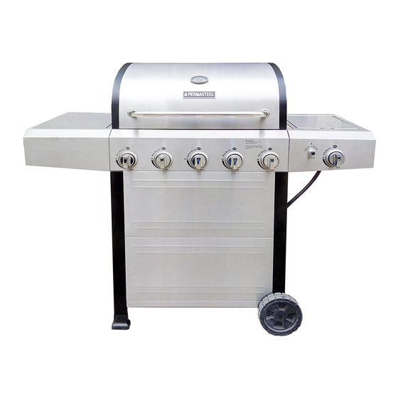
- Page 1 OWNER’S MANUAL Permasteel 5 Burners gas grill with Stainless Steel Lid Model No.: 40522S0LB Date of purchase:...
- Page 2 TABLE OF CONTENTS WARRANTY If any questions or concerns contact vendor at 1-888-287-0735 or email service@permasteel.net...
-
Page 3: Installation Safety Precautions
Installation Safety Precautions DANGER • Please read this User’s Manual in its entirety before using the grill. • The installer should leave instruction to the consumers to retain If you smell gas: them for future reference. • The consumers should keep the instruction for future reference. •... -
Page 4: Table Of Contents
For Your Safety ..2 Grill Service Center. . . One Year Limited Warranty on PERMASTEEL Grill WARRANTY If this grill fails due to a defect in material or workmanship Product Record Information . . . -
Page 5: Use And Care
LP Cylinder USE AND CARE • The LP cylinder used with your grill must meet the following requirements: DANGER • Use LP cylinders only with these required measurements: 12" (30.5cm) (diameter) x 18" (45.7 cm) (tall) with 20 lb. (9 kg.) Capacity maximum. - Page 6 LP Tank Exchange Connecting Regulator To The LP Tank • Many retailers that sell grills offer you the option of replacing 1. LP tank must be properly secured onto grill. (Refer to your empty LP tank through an exchange service. Use only those assembly section.) reputable exchange companies that inspect, precision fill, test 2.
- Page 7 3. Completely open LP tank valve by turning OPD hand wheel counterclockwise. If you hear a rushing sound, turn gas off immediately. There is a major leak at the connection. Correct before proceeding by calling Permasteel for replacement parts at 1-888-287-0735. Hold coupling nut and regulator 4 .Brush soapy solution onto areas where bubbles are shown in...
- Page 8 Safety Tips WARNING ▲ Before opening LP cylinder valve, check the coupling nut for tightness. ▲ When grill is not in use, turn off all control knobs and LP cylinder For Safe Use of Your Grill and to Avoid Serious valve.
- Page 9 Burner Flame Check WARNING • Remove cooking grates and heat diffusers. Light burners, turn knobs from HI to LO. You should see a smaller flame in LO position than seen on HI. Perform burner flame check Turn controls and gas source or tank OFF when not on sideburner, also.
-
Page 10: Spider Alert
Cleaning the Burner Assembly WARNING CAUTION Follow these instructions to clean and/or replace parts of burner assembly or if you have trouble igniting grill. 1. Turn gas off at control knobs and LP cylinder. SPIDER ALERT! SPIDER ALERT! SPIDER ALERT! 2. - Page 11 Indirect Cooking Food Safety Poultry and large cuts of meat cook slowly to perfection on the grill Food safety is a very important part of enjoying the outdoor by indirect heat. Place food over unlit burner(s); the heat from lit cooking experience.
-
Page 12: Parts List
PARTS LIST PARTS LIST Description Key Description Key Description Part Number Part Number HEAT DIFFUSERS 52200004 D06 Side Burner 52200053 COOKING GRATE A02 Temperature Gauge 52200015 D07 Right Side Shelf 52220047 SWING AWAY GRATE A03 Logo 52200300 D08 Electronic Ignition Module 40800122 CLIP, F/ GREASE CUP A04 Rotate Rod, Lid... -
Page 13: Parts Diagram
PARTS DIAGRAM B07 B06 B05... -
Page 14: Assembly
ASSEMBLY CAREFULLY READ AND PERFORM ALL ASSEMBLY INSTRUCTIONS ON THE FOLLOWING PAGES. Tools Required: Adjustable wrench (not provided) Screwdriver (not provided) 7/16” Combination wrench (not provided) The following hardware is provided in blister pack for convenient use. M4 X 10 screw AAA Battery Qty: 50 pcs Qty: 1 pc... - Page 15 Left Frame Install (4)M4×10 Screws as shown to the leg marked “5A”. Do not fully tighten the screws at this □ time. (A) □ Attach one end of Side Upper Rail to the leg, tighten the screws and attach with another (1)M4× 10 Screw.(B) □...
- Page 16 Right Frame □ Install (4)M4×10 Screws as shown to the leg marked “5C”. Do not fully tighten the screws at this time. (A) □ Attach one end of Side Upper Rail to the leg, tighten the screws and attach with another (1)M4×10 Screw.(B) □...
-
Page 17: Bottom Shelf
Bottom Shelf □ Install (4)M4×10 Screws as shown to right Frame. Do not fully tighten the screws at this time. (A) □ Attach Bottom Shelf to right Leg Frame with (3)M4×10 Screws. Do not tighten these screws. (A) □ Install (4)M4×10 Screws as shown to Left Frame. Do not fully tighten the screws at this time. (B) □... - Page 18 Top screw (a-1) (d-1)
- Page 19 Wheels to Cart □ Turn cart upside down, attach the Bottom Shelf to Four Legs with (4)M6×13 Screws as shown.(A) □Remove washer nut & hitch pin from axle rod Insert Axle Rod through Wheels and Right Leg Frame, Reattach with washer, nut and hitch pin.(B) □Tap both Leg Extenders onto Left Legs.(C) □...
- Page 20 Grill Head to Cart □ This step requires two people to lift and position grill head on to cart. □ Remove the tie wraps and packaging material from regulator hose, side burner valve and igniter wire. Pull hose and igniter wire out to side of grill head. □...
-
Page 21: Temperature Gauge
Temperature Gauge □ Place the Temperature Gauge through Lid and tighten with the Wing Nut. Left Side Shelf (1) □ Install the (2)M6×13 Screws on the left of Firebox. Do not fully tighten the screws. □ Place on the Left Side Shelf and pull to its position. M6X13 screw Qty: 2 pcs... - Page 22 NOTES Left Side Shelf (2) □ Open the Lid, attach the shelf to Firebox as follows: - From inside to outside of firebox with (2)M6×13 Screws and (2)M6 compression washers.(A) □ Align the Side Fascia and Control Panel, attach them from outside to inside of Firebox with (1)M4× 10 Screws.
- Page 23 Right Side Shelf (1) □ Install the (2)M6×13 Screws on the Right of Firebox. Do not fully tighten the screws. □ Place on the Right Side Shelf and pull to its position. M6X13 screw Qty: 2 pcs...
- Page 24 Right Side Shelf (2) □ Open the Lid, attach the shelf to Firebox as follows: - From inside to outside of firebox with (2)M6×13 Screws and (2)M6 compression washers.(A) □ Align the Side Fascia and Control Panel, attach them from outside to inside of Firebox with (1)M4× 10 Screws.
- Page 25 Side burner (The pictures just for your reference.) □ Loosen side burner in side shelf. (B ). To loosen, unscrew and remove two front screws and washers holding side burner in place. (A). Note: Do not loosen electrode screw. □ Remove the 2 pre-installed screws from the valve stem and set them aside. (C) □...
- Page 27 Heat Diffusers, Cooking Grates and Warming Rack □ Place Heat Diffusers over burners. Diffusers will fit in firebox in either direction. Fit tabs in firebox front through slots in Diffusers tips, Fit diffusers tips between tabs in Firebox Rear. □ Place Cooking Grates onto grate rests at front and rear of Firebox. □...
- Page 28 Drip Tray, Drip Cup and LP Tank □ Attach Back Rail to the Cart and Grill Head with (4)M4×10 Screws as shown.(A) □ Remove the cotter key and retention pin from the hose bracket on cart right leg. Insert hose into bracket and replace cotter and pin.
-
Page 29: Troubleshooting
EMERGENCIES: If a gas leak cannot be stopped, or a fire occurs due to gas leakage, call the fire department. •Turn off gas at LP cylinder or at source on natural gas systems. If the Gas leaking from • Damaged hose. hose is cracked or cut but not burned, simply replace valve / hose / cracked/cut/burned hose. - Page 30 Troubleshooting (continued) Problem Possible Cause Prevention/Solution Burner(s) will not light ELECTRONIC IGNITION: • See Section I of Electronic Ignition System. using ignitor. • No spark, no ignition noise. (See Electronic Ignition • See Section II of Electronic Ignition System. • No spark, some ignition noise. Troubleshooting also) •...
- Page 31 Troubleshooting - Electronic Ignition Problem (Ignition) Possible Cause Preventio SECTION I • Check battery orientation. • Install battery (make sure that “+” and “-” No sparks appear at • Battery not installed connectors are oriented correctly, with “+” end up any electrodes when properly.
- Page 32 Medidas de seguridad para la instalación PELIGRO • Por favor, lea este manual del usuario en su totalidad antes de usar la parrilla. • El incumplimiento de las enseñanzas impartidas en serio puede resultar en lesiones corporales y / o daños materiales. Si siente olor a gas: •...
-
Page 33: Euclid Ave Bldg
GARANTIA LIMITADA Por su propia seguridad ..31 Garantía limitada de un año en PERMASTEEL Grill Si esta parrilla falla debido a defectos de material o de mano Centro de servicio para parrillas..31 de obra dentro del plazo de un año desde la fecha de... - Page 34 UOS Y MANTENIMIENTO Tanque de gas propano • El tanque de gas que use con su parrilla debe cumplir los PELIGRO siguientes requisitos: • Use únicamente tanques de gas que tengan las siguientes medidas obligatorias: 12" (30.5 cm) (diámetro) x 18" (45.7 •...
- Page 35 Cambio del tanque de gas Como conectar el regulador al tanque de gas propano • Muchos comerciantes minoristas que venden parrillas, le 1. El tanque de gas debe quedar bien fijado a la parrilla. (Lea la ofrecen la opción de cambiar su tanque de gas vacío mediante sección de ensamblado.) un servicio de recambio.
- Page 36 Prueba para detectar fugas de las válvulas, las mangueras y el regulador 1. Gire todas las perillas de control de la parrilla a la posición deAPAGADO. 2. Cerciórese de que el regulador esté bien conectado al tanque de gas. 3. Abra por completo la válvula del tanque, girando la manilla en sonido sentido contrario a las agujas del reloj.
-
Page 37: Consejos De Seguridad
Consejos de seguridad ADVERTENCIA ▲ Verifique que la tuerca de unión esté bien apretada antes de abrir la válvula del tanque de gas. ▲ Cuando no use la parrilla, cierre todas las perillas de control Para usar su parrilla en forma segura y para evitar y la válvula del tanque de gas. - Page 38 Control de la llama del quemador ADVERTENCIA • Retire las parrillas de cocción y los reguladores de llama. Encienda los quemadores y gire las perillas, de la graduación ALTA (HI) a la graduación BAJA (LO). Deberá ver una llama más reducida en la Gire los controles y la fuente de gas o OFF tanque cuando graduación baja que en la graduación alta.
- Page 39 Cómo limpiar la unidad del quemador CAUTION Siga estas instrucciones para limpiar o cambiar piezas de la unidad del quemador, o si tiene problemas para encender la parrilla. 1. Cierre el paso de gas en las perillas de control y desde el tanque de gas.
- Page 40 Cocción indirecta Cocción: Cocine bien las carnes y las piezas de ave, para matar las bacterias. Use un termómetro para verificar que los alimentos Las aves y los cortes grandes de carne se cocinan lentamente a la alcancen la temperatura interna adecuada. perfección en la parrilla por calor indirecto.
-
Page 41: A03 Logo
LISTA DE PIEZAS Clave Descripción Cant Pieza No. Clave Descripción Pieza No. Description 52200004 52200053 Tapa quemador lateral 52200015 52220047 Indicador de temperatura Lado derecho del estante Módulo de encendido 52200300 40800122 Logo electrónico 50300207 52220049 Rote la vara, la tapa Fascia, estante lateral derecho Caucho de silicona parachoques, 40700103... - Page 42 DIAGRAMA DE PARTES DIAGRAMA DE PARTES B07 B06 B05...
- Page 43 ASAMBLEA Lea y realizar todas las INSTRUCCIONES DE MONTAJE En las siguientes páginas. Herramientas necesarias:: Llave ajustable (no incluido) destornillador (no incluido) 7/16” Llave combinada (no incluido) El siguiente hardware se proporciona en blister para el uso conveniente. M4X10 tornillo AAA Batería Qty: 58 pcs Qty: 1 pc...
- Page 44 Cuadro izquierdo Instalar (4) M4 × 10 Tornillos como se muestra a la pata marcada "5A". No apriete los tornillos □ en este momento. (A) □ Conecte un extremo de la parte superior del carril a la pierna, apriete los tornillos y conectar con otro (1) M4 ×...
- Page 45 cuadro derecho □ Instalar (4) M4 × 10 Tornillos como se muestra a la pata marcada "5C". No apriete los tornillos en este momento. (A) □ Conecte un extremo de la parte superior del carril a la pierna, apriete los tornillos y conectar con otro (1) M4 ×...
- Page 46 Bottom Shelf Instalar (4) M4 × 10 Tornillos como se muestra a la derecha del marco. No apriete los tornillos en □ este momento. (A) □ Adjuntar estante inferior al cuadro derecho Pierna con (3) M4 × 10 Tornillos. No apriete los tornillos.
- Page 47 M4x10 Tornillos Qty: 6 pcs (a-1) (d-1)
- Page 48 Ruedas a la Cesta □ Gire a la cesta boca abajo, coloque los tornillos restantes del estante inferior y cuatro patas con (4) M6 × 13 Tornillos como se muestra. (A) □ Toque en tanto la pierna extensores en el pie derecho de la pierna. (B) □...
- Page 49 Grill Cabeza a la Cesta □Este paso requiere de dos personas para levantar la cabeza y la posición en la parrilla de la compra. □ Retire las abrazaderas y material de embalaje de la manguera del regulador, válvula del quemador lateral y el cable de encendido. Tire de la manguera y el cable de encendido a lado de la cabeza de la parrilla.
- Page 50 Indicador de temperature □Coloque el indicador de temperatura a través de la tapa y apriete con la Tuerca de mariposa. Left Side Shelf (1) □ Instale el (2) M6 × 13 Tornillos de la izquierda del Firebox. No apriete completamente los tornillos. □...
- Page 51 NOTES Left Side Shelf (2) □ Abra la tapa, coloque la plataforma de la caja de fuegos de la siguiente manera: - Desde el interior al exterior de la cámara de combustión con (2) M6 × 13 Tornillos y (2) arandelas de compresión M6 (A).
- Page 52 Right Side Shelf (1) □ Instale el (2) M6 × 13 Tornillos sobre el derecho de Firebox. No apriete completamente los tornillos. □ Coloque en el soporte del lado derecho del estante y saque a su posición. M6X13 Tornillos Qty: 2...
- Page 53 Right Side Shelf (2) □ Abra la tapa, coloque la plataforma de la caja de fuegos de la siguiente manera: - Desde el interior al exterior de la cámara de combustión con (2) M6 × 13 Tornillos y (2) arandelas de compresión M6 (A).
- Page 54 quemador lateral (Las imágenes sólo para su referencia.) □Afloje quemador lateral en la repisa lateral. (B). Para aflojar, desenroscar y quitar dos tornillos delanteros y arandelas que sostienen quemador lateral en su lugar. (A). Nota: No afloje el tornillo del electrodo.
- Page 56 Los difusores de calor, parrillas de cocción y calentamiento rack □ Coloca difusores de calor sobre los quemadores. Los difusores se ajusta en la cámara de combustión en cualquier dirección. Lengüetas de ajuste frente cámara de combustión a través de ranuras en consejos Difusores, difusores consejos ajuste entre pestañas en Firebox posterior.
- Page 57 Bandeja de goteo, goteo de la Copa y el tanque de gas □ Adjuntar Volver Rail a la Cesta and Grill Cabeza con (4) M4 × 10 Tornillos como se muestra. (A) □ Retire la llave de chaveta y el pasador de retención del soporte de la manguera en la cesta de la pierna derecha.
- Page 58 EMERGENCIES: If a gas leak cannot be stopped, or a fire occurs due to gas leakage, call the fire department. •Turn off gas at LP cylinder or at source on natural gas systems. If the Gas leaking from • Damaged hose. hose is cracked or cut but not burned, simply replace valve / hose / cracked/cut/burned hose.
- Page 59 Troubleshooting (continued) Problem Possible Cause Prevention/Solution Burner(s) will not light ELECTRONIC IGNITION: • See Section I of Electronic Ignition System. • No spark, no ignition noise. using ignitor. (See Electronic Ignition • See Section II of Electronic Ignition System. Troubleshooting also) •...
- Page 60 Troubleshooting - Electronic Ignition Problem (Ignition) Possible Cause Preventio SECTION I • Check battery orientation. • Install battery (make sure that “+” and “-” No sparks appear at • Battery not installed connectors are oriented correctly, with “+” end up any electrodes when properly.
Need help?
Do you have a question about the 40522S0LB and is the answer not in the manual?
Questions and answers