Table of Contents
Advertisement
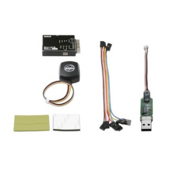
1.Dimensions:Main controller: 53.5 x 38.5 x 12mm
Weight:Main controller: 27g (w/o cables ), GPS antenna: 23g (with cable)
2.Frequency: 300Hz output to ESC
3.Operating temperature: -20~80°C
4.Operating modes: Rate (manual) mode, Auto balance mode, GPS positioning mode.
5.Rate (manual) mode: Max angular velocity: 300 degree/sec.
6.Auto balance mode: Max tilt angle: 60 degree.
7.GPS positioning mode:
a.Hovering accuracy: Horizontal: ±2m, Vertical: ±0.5m
b.Max yaw angular velocity: 250 degree/sec
c.Max tilt angle: 45 degree.
d.Max horizontal speed: 10 m/s,36 km/hr
e.Max vertical speed: 8 m/s (horizontal posture)
8.GU-INS provides pitch and rolls output signals, can work with different types of camera mounts.
9.Fail-safe functions: Automatic Go-Home, Signal lost Go-Home, Low voltage protection.
10.Suitable wind condition: < 10 m/s
Assembly Instruotion
●Specifications :
GPS antenna: 42 x 34 x 15mm
GAUI
Advertisement
Table of Contents

Related Manuals for GAUI GU-INS


Summary of Contents for GAUI GU-INS
-
Page 1: Specifications
10 m/s,36 km/hr e.Max vertical speed: 8 m/s (horizontal posture) 8.GU-INS provides pitch and rolls output signals, can work with different types of camera mounts. 9.Fail-safe functions: Automatic Go-Home, Signal lost Go-Home, Low voltage protection. 10.Suitable wind condition: < 10 m/s... -
Page 2: Table Of Contents
10 m/s,36 km/hr e.Max vertical speed: 8 m/s (horizontal posture) 8.GU-INS provides pitch and rolls output signals, can work with different types of camera mounts. GPS system 9.Fail-safe functions: Automatic Go-Home, Signal lost Go-Home, Low voltage protection. - Page 3 GU-INS. (The screws of GU-INS are made of copper.) 11.If the 500X can not make a 360 degree turn, it reprents that the magnetometer of GU-INS is interfered. Please keep away from sources of interference or execute the calibration process. (Please visit GAUI official website for detail information.)
-
Page 4: Low Voltage Protection
Index for LED Light Status 1 sec 1.SET: Off---- Normal Flashes 3 times and turn off---- Setup is completed. Solid---- Execute low voltage protection function. 2.GPS: Off---- GPS system is not inserted. Fast flashing---- Execute “HOME” function. Slow flashing---- Searching GPS signals. Solid---- GPS signal searching procedure is completed. -
Page 5: System Assembly
System Assembly 1.Install the damper sponges to the corners under GU-INS. *Please keep GU-INS away from magnetic material. 2.Install the GU-INS to the center of the platform. - Page 6 Red/Orange/Yellow White/Red/Black (AIL) 3.Insert the 2 and 6 channel connection cables to the GU-INS main controller. 4.Insert the plugs of ESCs (1~4) to the given sockets of GU-INS. (Notice the position and spinning direction of the motors.)
- Page 7 System Assembly White/Red/Black AILE Green FLAP(Mode) ELEV Blue GEAR(Go Home) Orange THRO Black AUX2(Camera Mount Pitch Axis) Yellow RUDD 5.Insert the plugs of receiver to GU-INS as illustrated. Futaba Hitech AILE Reverse Normal Normal ELEV Reverse Normal Reverse THRO Normal Reverse...
-
Page 8: System Setting
System Setting 1.For your safety, before setup, please remove the propellers, and notice the LED lights on the GU-INS. MODE 1 3.Connect the battery to the 500X, the motors will come up 2.Turn on the transmitter, and move the with corresponding tones, and the LED light of “MODE”... - Page 9 LED lights. Ex: channel assignment for JR DSX7 and DSX9: Home function Fly mode Camera gimbal Insert the “Bind plug” to the “AIL” slot before binding the transmitter and GU-INS (For your safety, please remove the propellers before binding.)
-
Page 10: System Tuning
System Tuning 2.Connect the battery to the 500X, after the 1.Install the propellers, turn on the transmitter, and switch to corresponding tones of ESCs, you are ready “Manual” mode. for test flight. MODE 1 3.Move the throttle stick gradually until the 500X slightly lift off. MODE 1 4.Move the “ELE”... - Page 11 System Tuning MODE 1 5.Check and make sure the “AIL” movement follow your transmitter command. MODE 1 6.Check and make sure the “RUD” movement follow your transmitter command. The recommanded initial setting of GAIN and Z GAIN value is about central position of the knob. (as illustrated) 7.After checking all movements of the 500X are correct, hover the 500X about 1m above the ground, if it shakes or wags while hovering, decrease the “GAIN”...
- Page 12 System Tunning 1.5m 8.Hover about 1.5m above the ground, calibrate the attitude of 500X with trimmers of the transmitter. 10.“SET” LED light flashes three 11.Set all trims to neutral times when calibration under after calibration. 9.Press “SET” buttom when manual mode is completed. calibration is completed.
-
Page 13: Gps Navigation
(The GPS system is not aeolotropic, the mark on top of it should be faced upward.) 3.Connect the battery of the 500X, the LED light of “GPS” 2.Turn on the transmitter. will start to flash, and the GU-INS will start to search for GPS signal. - Page 14 GPS Navigation 5.You can verify how many satellites are received by 4.When the GU-INS has found more than five satellites, the LED light of “GPS” will turn pressing the buttom and count the number of LED solid green. We recommand to wait one more flashes(as illustrated).
- Page 15 GPS Navigation MODE 1 10.You can also take off with “Auto-balance” mode (turn 11.Climb to the altitude you want, and switch switch as indicated above), the MODE LED light will back to “GPS positioning” mode. turn into fast green flash. MODE 1 12.Move the throttle stick upward, and the 500X will start to climb.
- Page 16 GPS Navigation MODE 1 14.Move the throttle stick downward, the 500X will start to decend. MODE 1 15.If the 500X heads to the left while you move the “ELE” stick forward, please adjust the “HEAD” knob to the right, this is the calibration of magnetic north and due north of different area.
- Page 17 GPS Navigation MODE 1 16.Z gain is used for adjusting the gain value of altitude, it may be affected by wind or air pressure, thus we recommand to adjust it to central position (as illustrated). MODE 1 17.The 500X can decend slowly to the ground 18.The propellers would not stop until switched back under GPS positioning mode.
-
Page 18: Go-Home Function
Go-Home Function 1.While just starting the GPS system, the “Home” position may be within a radius of 5m. 3.Then press “SET” buttom under GPS positioning 2.By increasing the numbers of satellites received mode will make the “Home” position setting to be and wait for convergence of signal, the precision more accurate. - Page 19 Go-Home Function 5.When switching to “Home” function, the 500X will turn its head toward “Home” location and start returning to “Home” position. If its altitude is more than 10m, it will decend to 10m height after arriving at “Home” position. If its altitude is below 10m, it will maintain altitude and hover.
- Page 20 Low Voltage Protection 1.When you first insert the plug to the second cell (positive pole) of the balance plug of battery, and then connect the battery to the 500X, the low voltage protection function will be activated. (LED light of SET turn solid.) 2.If you connect the battery to the 500X first, then insert the plug, the low voltage protection function will not be activated, but the voltage will be shown on the OSD.
- Page 21 Low Voltage Protection MODE 1 MODE 1 6.You need to move throttle stick upward more 5.When the low voltage protection function is activated, to maintain altitude and hover at this time. the throttle signal will decrease 20%, and the 500X will decend.
-
Page 22: Camera Gimbal Calibration
Camera Gimbal Calibration Horizontal axis servo Vertical axis servo 1.Insert the wire of vertical axis servo to “P-CAM” socket, wire of horizontal axis servo to “R-CAM” socket, and place the 500X on a flat platform for the follow calibration and setting procedures. 3.Adjust the range of vertical axis as you want 2.Adjust the neutral position of horizontal axis with side lever of the transmitter. - Page 23 5.Turn on the transmitter first, and then connect the battery of 4.For your safety, please remove the propellers before setup. GU-INS the 500X, press “SET” buttom before the initialization of is completed. 6.The system will start the calibration 7.The angle of the camera gimbal presents would be datum line A.
- Page 24 Camera Gimbal Calibration MODE 1 9.Press SET buttom to confirm, then 8.Raise one side of the pole (vertical axis of camera gimbal), calibrate the camera gimbal with ELE stick, adjust the the second LED light (GPS) flashes. camera gimbal to be parallel to datum line A. MODE 1 10.Raise the other side of the pole (vertical axis of camera gimbal), 11.Press SET buttom to confirm, then...
- Page 25 Camera Gimbal Calibration MODE 1 15.Press SET buttom to confirm, then 14.Raise the other side of the pole (horizontal axis of camera gimbal) the LED lights of SET, GPS, MODE, , adjust the camera gimbal to level with AIL stick as previous step. SENSOR will flash then turn off, and the calibration of camera gimbal is completed.
-
Page 26: Firmware Update
3.Connect the USB cable to the PC, it will socket of GU-INS. download the driver automatically. 5.Download the firmware from the official website 6.Select the appropriate COM (the system will search of GAUI, and double click the .exe file. Follow it automatically). the steps to finish installation. - Page 27 Firmware Update 8.The system will start to execute the firmware updating procedure (the ESCs will come with 7.Then click “Execute”. sounds, LED light of “MODE” turn red flash). 9.As the updating procedures is completed (as display on PC), the sounds of ESCs 10.Remove the USB cable, the firmware will stop, LED light of “MODE”...
- Page 28 *Make sure your transmitter module would not interfere the GPS system. (Keep the transmitter away from the GPS system to minimize possible radio interference.) Insert the connection cable of GU-OSD to the “OSD” socket on GU-INS, and connect the other end to your OSD devices. Option...
- Page 29 On Screen Display Interface Fly mode (R- Manual, A- Auto balance, G- GPS positioning) Numbers of satellites received Attitude Straight distance Residual battery Altitude Operating time Speed capacity Direction of the aircraft heading Position of the aircraft Home The central area of the OSD image displays as a radar chart (as illustrated), and the relative distance represents on the display is 500m (y-axis) X 1000m (x-axis).
Need help?
Do you have a question about the GU-INS and is the answer not in the manual?
Questions and answers