Nordson Tribomatic II Customer Product Manual
Automatic powder spray gun
Hide thumbs
Also See for Tribomatic II:
- Customer product manual (41 pages) ,
- Instruction sheet (16 pages) ,
- Customer product manual (36 pages)
Table of Contents
Advertisement
Quick Links
r
Tribomatic
II Automatic
Powder Spray Gun
Customer Product Manual
Part 106571F
Issued 10/02
For parts and technical support, call the Industrial Coating
Systems Customer Support Center at (800) 433-9319
This document is subject to change without notice.
Check http://emanuals.nordson.com/finishing for the latest version.
NORDSON CORPORATION AMHERST, OHIO USA
Advertisement
Table of Contents

Related Manuals for Nordson Tribomatic II


Summary of Contents for Nordson Tribomatic II
- Page 1 Part 106571F Issued 10/02 For parts and technical support, call the Industrial Coating Systems Customer Support Center at (800) 433-9319 This document is subject to change without notice. Check http://emanuals.nordson.com/finishing for the latest version. NORDSON CORPORATION AMHERST, OHIO USA...
- Page 2 This is a Nordson Corporation publication which is protected by copyright. Original copyright date 1992. No part of this document may be photocopied, reproduced, or translated to another language without the prior written consent of Nordson Corporation. The information contained in this publication is subject to change without notice. 2002 All rights reserved.
-
Page 3: Table Of Contents
..... Inner/Outer Wear Sleeve Service Kit Installation ... . . Part 106571F E 2002 Nordson Corporation... - Page 4 ........8-15 Part 106571F E 2002 Nordson Corporation...
-
Page 5: Safety
Regulations and Approvals Make sure all equipment is rated and approved for the environment in which it is used. Any approvals obtained for Nordson equipment will be voided if instructions for installation, operation, and service are not followed. All phases of equipment installation must comply with all federal, state, and local codes. -
Page 6: Personal Safety
Clean, maintain, test, and repair equipment according to the instructions in your equipment documentation. Use only replacement parts that are designed for use with original equipment. Contact your Nordson representative for parts information and advice. Part 106571F E 2002 Nordson Corporation... -
Page 7: Grounding
Disconnect and lock out electrical power. Close pneumatic shutoff valves and relieve pressures. Identify the reason for the malfunction and correct it before restarting the equipment. Disposal Dispose of equipment and materials used in operation and servicing according to local codes. Part 106571F E 2002 Nordson Corporation... -
Page 8: Safety Label
14. Guns, feeders, booths, etc., may be cleaned with clean dry air at 1.7 bar (25 psig). If you have any questions concerning this electrostatic spray equipment, call (216) 988-9411, and ask to speak with the Powder Systems Group Technical Service Department. Part 106571F E 2002 Nordson Corporation... -
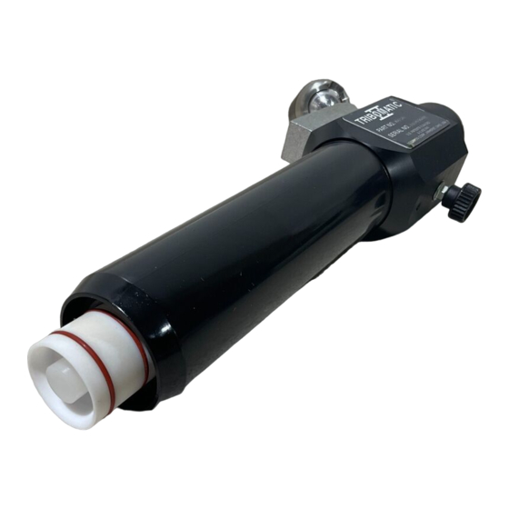
Page 9: Description
Tribomatic automatic spray gun. Options are listed in Table 2-1. Table 2-2 describes the characteristics of materials used in the Tribomatic II guns: PTFE, nylon, and Tivar. Use this table to identify the materials used in your spray gun. -
Page 10: Operation
Options The options listed in Table 2-1 are available for use with the Tribomatic II automatic spray gun. Refer to the Options section for part numbers and descriptions. -
Page 11: Material Descriptions
Material Descriptions Table 2-2 contains descriptions of the three types of plastics used in the Tribomatic II spray guns and the powder compatible with each type. Use this table to determine the types of plastics used in your spray gun. - Page 12 Description Part 106571F E 2002 Nordson Corporation...
-
Page 13: Installation
4. Slide the adjuster down the mounting bar. Thread it onto the ball mount cap. 5. Make sure the M6 x 8 set screw (8) is tightened. 6. Rotate the spray gun to the desired position, then tighten the adjuster to lock the spray gun into position. Part 106571F E 2002 Nordson Corporation... -
Page 14: Feed Hose, Air Tubing, And Ground Wire Connections
Installation Figure 3-1 Mounting the Tribomatic II Automatic Spray Gun 1. Fixed gun stand or gun mover 4. Adjuster 7. Ball mount cap 5. Ball mount flange 8. M6 x 8 set screw 2. Gun mounting bar assembly 6. Set screws 3. - Page 15 7. Air tubing 3. Sprayhead 6. See Figure 3-2. Install the sprayhead (3) on the end of the charge module body (2) with a twisting motion. 7. Adjust the spray gun-to-workpiece distance and position. Figure 3-3 Part 106571F E 2002 Nordson Corporation...
-
Page 16: Installing Nozzles On Sprayheads
To existing sprayhead tube ends or threaded or angled nozzles Figure 3-4 Installing Nozzles on Sprayheads 1. Cylindrical nozzles 3. Pinpoint nozzles 5. Threaded nozzles 2. Flat nozzles 4. Eight-orifice nozzles 6. Angled nozzles without threads Part 106571F E 2002 Nordson Corporation... -
Page 17: Operation And Maintenance
Experiment with the part hanger configuration and part density. Reduce the space between parts to keep overspray to a minimum. Keep the air velocity through the booth as close to the minimum required by law as practical without violating safety. Part 106571F E 2002 Nordson Corporation... -
Page 18: Daily Maintenance
The resistance from part to ground, through the hangers and conveyor, must not exceed one megohm. For best results, the resistance should be less than 500 . Part 106571F E 2002 Nordson Corporation... -
Page 19: Troubleshooting
This section contains troubleshooting procedures. These procedures cover only the most common problems that you may encounter. If you cannot solve the problem with the information given here, contact your local Nordson representative for help. Problem Possible Cause Corrective Action 1. - Page 20 Flow rate air pressure too low Increase the flow rate air pressure. flow Wet powder clogging system Check the air filters, dryer, and powder supply. Service the filters and/or the dryer and change the powder supply. Part 106571F E 2002 Nordson Corporation...
-
Page 21: Repair
Follow the safety instructions in this document and all other related documentation. Introduction See Figure 6-1. The Tribomatic II automatic spray gun is easily disassembled. Two main service kits are available: Wear sleeve service kit—consists of the parts subject to the most wear (inner and outer wear sleeves, spacing ring, and positioning ring). -
Page 22: Cleaning
3. Leave the ground wire attached to the spray gun. Make sure the booth exhaust fan is running. 4. Blow out the feed tubing, diffuser, and charge module. 5. Pull the diffuser from the gun body and blow out the charge module again. 6. Remove the sprayhead. Part 106571F E 2002 Nordson Corporation... -
Page 23: Charge Module Service Kit Installation
NOTE: The body pins are replaceable. If you break or bend them, unscrew them from the body and install new ones. Figure 6-3 Charge Module Service Kit Installation—Steps 1 and 2 1. Body 3. Extension 4. Outer wear sleeve assembly 2. Inner/outer wear sleeve assembly Part 106571F E 2002 Nordson Corporation... - Page 24 6. Remove the outlet wear sleeve assembly (2) from the service kit and install it in the extension (4). Figure 6-5 Charge Module Service Kit Installation —Steps 5 and 6 1. Inlet wear sleeve assembly 3. Body 4. Extension 2. Outlet wear sleeve assembly Part 106571F E 2002 Nordson Corporation...
- Page 25 Charge Module Service Kit Installation —Steps 7 and 8 1. Body 3. Positioning ring 5. Extension 2. Inner/outer wear sleeve 4. Spacing ring assembly 9. Install the sprayhead and diffuser. Connect the powder feed tubing and diffuser air line. Part 106571F E 2002 Nordson Corporation...
-
Page 26: Inner/Outer Wear Sleeve Service Kit Installation
5. Screw the inlet distributor onto one end of the threaded rod. Insert the threaded rod into the positioning ring end of the inner wear sleeve. Screw the outlet distributor onto the threaded rod and tighten it securely by hand. Part 106571F E 2002 Nordson Corporation... - Page 27 Inner/Outer Wear Sleeve Installation —Steps 6 and 7 1. Inner wear sleeve 3. Outer wear sleeve 2. Positioning ring 4. Spacing ring 8. Perform steps 7, 8, and 9 under Charge Module Service Kit Installation. Part 106571F E 2002 Nordson Corporation...
- Page 28 Repair Part 106571F E 2002 Nordson Corporation...
-
Page 29: Parts
A dash (—) is used when the part number applies to all parts in the illustration. The number in the Part column is the Nordson Corporation part number. A series of dashes in this column (- - - - - -) means the part cannot be ordered separately. -
Page 30: Ptfe Charge Module
B: These parts available in inner/outer wear sleeve service kit, part 631208. C: These parts available in positioning and spacing ring service kit, part 631209. D: Limited service part. Must provide gun part number and serial number when ordering. Part 106571F E 2002 Nordson Corporation... - Page 31 Parts Figure 7-1 Charge Module Part 106571F E 2002 Nordson Corporation...
-
Page 32: In-Line Ball Mount Kit
S S PLATE, adapting, ball mount 982186 S SCREW, flat head, slotted, M8 x 20, zinc 129592 KNOB, clamping, M6 x 12 NOTE A: Optional equipment, replaces item 8. Figure 7-2 In-line Ball Mount Kit Part 106571F E 2002 Nordson Corporation... -
Page 33: Diffuser
Parts Diffuser See Figure 7-3. Item Part Description Quantity Note — 631271 DIFFUSER, Tribomatic II, single 972080 S CONNECTOR, male, -in. NPTF x -in. tube 635007 S NOZZLE, diffuser 940117 S O-RING, silicone, 0.312 x 0.438 x 0.063 in. 635008... -
Page 34: Inner/Outer Wear Sleeve Service Kit
S S O-RING, silicone, 1.375 x 1.500 x 0.063 in. 631216 S SLEEVE, wear, inner, PTFE 631210 S RING, positioning NOTE A: Also available as a set. Order positioning and spacing ring service kit, part 631209. Figure 7-4 Inner/Outer Wear Sleeve Service Kit Part 106571F E 2002 Nordson Corporation... -
Page 35: Positioning And Spacing Ring Service Kit
PTFE or nylon charge modules. Item Part Description Quantity Note — 631209 SERVICE KIT, positioning and spacing rings 631220 S RING, spacing 631210 S RING, positioning Figure 7-5 Positioning and Spacing Ring Service Kit Part 106571F E 2002 Nordson Corporation... -
Page 36: Ptfe Charge Module Service Kit
- - - - - - S S SLEEVE, wear, inlet, PTFE 940243 S S O-RING, silicone, 1.125 x 1.250 in. NOTE A: Also available as a set. Order positioning and spacing ring service kit, part 631209. Part 106571F E 2002 Nordson Corporation... - Page 37 Parts Kit, part 631 207 Figure 7-6 PTFE Charge Module Service Kit Part 106571F E 2002 Nordson Corporation...
- Page 38 7-10 Parts Part 106571F E 2002 Nordson Corporation...
-
Page 39: Options
- - - - - - S SLEEVE, wear, inner 631210 S RING, positioning NOTE A: Also available as a set. Order positioning and spacing ring service kit, part 631209. Figure 8-1 Nylon Inner/Outer Wear Sleeve Service Kit Part 106571F E 2002 Nordson Corporation... -
Page 40: Nylon Charge Module Service Kit Parts List
- - - - - - S S SLEEVE, wear, inlet, nylon 940243 S S O-RING, silicone, 1.125 x 1.250 x 0.063 in. NOTE A: Also available as a set. Order positioning and spacing ring service kit, part 631209. Part 106571F E 2002 Nordson Corporation... - Page 41 Options Kit, part 631 326 Figure 8-2 Nylon Charge Module Service Kit Part 106571F E 2002 Nordson Corporation...
-
Page 42: Diffuser With Purge
S CONNECTOR, diffuser, PVC 972916 S CONNECTOR, male -in. BSPT x 10-mm tube 939247 S CLAMP, hose, 0.781−0.875 in. 247006 S CLAMP, hose, 0.673−0.795 in. NS: Not Shown Figure 8-3 Diffuser with Purge Parts Part 106571F E 2002 Nordson Corporation... -
Page 43: Sprayheads
Options Sprayheads See Figures 8-4, 8-5, and 8-6. Special sprayhead designs can be requested. Contact your Nordson representative. Item Part Description Note 630006 ADJUSTABLE, 8 tubes 630009 EXPANDABLE, 8 tubes 630010 SHORT, 8 tubes 630330 FIXED, 100 mm, 8 tubes... - Page 44 FIXED, 2 row, 260 mm, 16 tubes NOTE A: Noted sprayheads include cylindrical nozzles, part 630017. B: Noted sprayheads include cylindrical nozzles, part 630340. Continued on next page Figure 8-5 Sprayheads (Drawings not to Scale) Part 106571F E 2002 Nordson Corporation...
- Page 45 CROSS, 45_, 460 mm, 16 tubes 630370 CROSS, 45_, 500 mm, 16 tubes NOTE A: Noted sprayheads include cylindrical nozzles, part 630017. B: Noted sprayheads include cylindrical nozzles, part 630340. Figure 8-6 Sprayheads (Drawings not to Scale) Part 106571F E 2002 Nordson Corporation...
-
Page 46: Eight-Tube Sprayhead Nozzles
630018 FLAT 630019 8 ORIFICE 630166 PINPOINT 630092 NOZZLE, threaded 630093 NOZZLE, threaded 630094 NOZZLE, threaded 630095 NOZZLE, threaded 630182 630096 630097 630098 630181 135_ Figure 8-7 Eight-Tube Sprayhead Nozzles (Drawings not to Scale) Part 106571F E 2002 Nordson Corporation... -
Page 47: 16-Tube Sprayhead Nozzles
630017 S CYLINDRICAL, nozzle 630092 S THREADED A, nozzle 630093 S THREADED D, nozzle 630094 S THREADED C, nozzle 630095 S THREADED B, nozzle 630096 S 45 DEGREE, nozzle 630097 S 90 DEGREE, nozzle Part 106571F E 2002 Nordson Corporation... -
Page 48: Lance Extensions
S S O-RING, silicone, 0.125 x 0.250 x 0.063 in. NOTE A: A Tivar deflector with no holes is available. Order part 133734. B: This part replaces the plug in the end of the outlet distributor. Figure 8-9 Lance Extensions Part 106571F E 2002 Nordson Corporation... -
Page 49: Shur-Lok Gun Mount
S SCREW, set, cup, M5 x 5, black 983527 S WASHER, flat, 0.344 x 1.125 x 0.063 in. 133415 S KNOB, gun mount 981708 S SCREW, oval, slot, M8 x 20, black NS: Not Shown Figure 8-10 Shur-Lok Gun Mount Part 106571F E 2002 Nordson Corporation... -
Page 50: Gun Mounting Bar
The mounting bar clamp is designed for 1-in. round or square tubing. Part Description Quantity 133403 BAR, gun, Versa-Spray 90 cm (3 ft) Figure 8-11 Gun Mounting Bar Part 106571F E 2002 Nordson Corporation... -
Page 51: Gun Holder Adapter Kit
See Figure 8-12. This kit allows you to use old style Tribomatic gun holders with the Tribomatic II charge module. Cut the ground wire to length, crimp ring-tong terminals to the ends of the wire, and attach the wire to the ground clips. -
Page 52: Powder Feed Hose And Air Tubing
TUBING, polyurethane, 6-mm OD, blue 630597 TUBING, PVC, 6-mm OD, blue 630598 TUBING, PVC, 4-mm OD, black NOTE A: Order in 1-m increments from Nordson Corporation, European Distribution Center. B: Order in 1-ft increments from Nordson Corporation, Amherst, Ohio. Miscellaneous Options Part Description... -
Page 53: Versa-Spray Nozzles
8-15 Options Versa-Spray Nozzles Nordson Versa-Spray gun nozzles can be used on the Tribomatic II spray guns. They must be installed on one of the optional lance extensions listed in this section. For more information, contact your Nordson Corporation representative, or refer to one of the following manuals for descriptions and part numbers. - Page 54 8-16 Options Part 106571F E 2002 Nordson Corporation...
- Page 55 Label on the applicator reads: EN50177 – Type A / ATEX II 3 D CERTIFICATIONS: ISO 9001 DNV ATEX Quality Notification (Notified Body No. 1180) Date: 18 October, 2007 Joseph Schroeder Engineering Manager, Finishing Product Development Group Nordson Corporation S Westlake, Ohio DOC14008A02...
Need help?
Do you have a question about the Tribomatic II and is the answer not in the manual?
Questions and answers