Nordson Tribomatic II Customer Product Manual
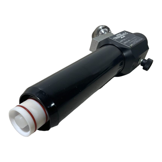
Extended automatic powder spray gun
Hide thumbs
Also See for Tribomatic II:
- Customer product manual (55 pages) ,
- Instruction sheet (16 pages) ,
- Customer product manual (36 pages)
Table of Contents
Advertisement
Quick Links
Download this manual
See also:
Customer Product Manual
r
Tribomatic
II Extended Automatic
Powder Spray Gun
Customer Product Manual
Part 334691B03
Issued 7/06
For parts and technical support, call the Industrial Coating
Systems Customer Support Center at (800) 433-9319 or
contact your local Nordson representative.
This document is subject to change without notice.
Check http://emanuals.nordson.com for the latest version.
NORDSON CORPORATION AMHERST, OHIO USA
Advertisement
Table of Contents

Related Manuals for Nordson Tribomatic II


Summary of Contents for Nordson Tribomatic II
- Page 1 For parts and technical support, call the Industrial Coating Systems Customer Support Center at (800) 433-9319 or contact your local Nordson representative. This document is subject to change without notice. Check http://emanuals.nordson.com for the latest version. NORDSON CORPORATION AMHERST, OHIO USA...
-
Page 2: Table Of Contents
555 Jackson Street Amherst, OH 44001 Notice This is a Nordson Corporation publication which is protected by copyright. Original copyright date 2000. No part of this document may be photocopied, reproduced, or translated to another language without the prior written consent of Nordson Corporation. The information contained in this publication is subject to change without notice. -
Page 3: Safety
Regulations and Approvals Make sure all equipment is rated and approved for the environment in which it is used. Any approvals obtained for Nordson equipment will be voided if instructions for installation, operation, and service are not followed. All phases of equipment installation must comply with all federal, state, and local codes. -
Page 4: Personal Safety
Clean, maintain, test, and repair equipment according to the instructions in your equipment documentation. Use only replacement parts that are designed for use with original equipment. Contact your Nordson representative for parts information and advice. Part 334691B03 E 2006 Nordson Corporation... -
Page 5: Grounding
Disconnect and lock out electrical power. Close pneumatic shutoff valves and relieve pressures. Identify the reason for the malfunction and correct it before restarting the equipment. Disposal Dispose of equipment and materials used in operation and servicing according to local codes. Part 334691B03 E 2006 Nordson Corporation... - Page 6 Safety Part 334691B03 E 2006 Nordson Corporation...
-
Page 7: Description
Options are listed in Table 2-1. Table 2-2 lists the characteristics of the PTFE and Tivar materials used in the Tribomatic II powder spray guns. Use this table to identify the materials used in your spray gun. 1400342A... -
Page 8: Operation
Material Descriptions Table 2-2 describes the two types of plastics used in the Tribomatic II powder spray guns and the powder compatible with each type. Use this table to determine which type of plastic is used in your spray gun. -
Page 9: Installation
5. Rotate the spray gun to the desired position, then tighten the gun mount adjuster (6). 1400343A Figure 3-1 Mounting the Tribomatic II Extended Automatic Powder Spray Gun 1. Fixed gun stand or gun mover arm 3. Gun mount adjuster 5. Gun holder adjuster 2. -
Page 10: Feed Hose, Air Tubing, And Ground Wire Connections
Figure 3-2 Connecting Feed Hose, Air Tubing, and Ground Wire 1. Diffuser 4. Charge module body 7. Powder feed hose 2. Ground Stud 5. Sprayhead 8. 6-mm Blue air tubing 3. Extension 6. Ground wire Part 334691B03 E 2006 Nordson Corporation... - Page 11 (4) with a twisting motion. Tighten the set screws around the circumference of the charge module body to secure the sprayhead. 8. Adjust the spray gun-to-workpiece distance and position. 1400406A Figure 3-3 Removing the Nozzle Cone 1. Nozzle cone 2. Sprayhead base Part 334691B03 E 2006 Nordson Corporation...
-
Page 12: Installing Nozzles On Sprayheads
To existing sprayhead tube ends or threaded or angled nozzles 1400407A Figure 3-4 Installing Nozzles on Sprayheads 1. Cylindrical nozzles 3. Pinpoint nozzles 5. Threaded nozzles 2. Flat nozzles 4. Eight-orifice nozzles 6. Angled nozzles without threads Part 334691B03 E 2006 Nordson Corporation... -
Page 13: Operation
Experiment with the part hanger configuration and part density. Reduce the space between parts to keep overspray to a minimum. Keep the air velocity through the booth as close to the minimum required by law as practical without violating safety. Part 334691B03 E 2006 Nordson Corporation... -
Page 14: Daily Maintenance
The resistance from part to ground, through the hangers and conveyor, must not exceed one megohm. For best results, the resistance should be less than 500 ohms. Part 334691B03 E 2006 Nordson Corporation... -
Page 15: Troubleshooting
This section contains troubleshooting procedures. These procedures cover only the most common problems that you may encounter. If you cannot solve the problem with the information given here, contact your local Nordson representative for help. Problem Possible Cause Corrective Action... - Page 16 Flow rate air pressure too low Increase the flow rate air pressure. flow Wet powder clogging system Check the air filters, dryer, and powder supply. Service the filters and/or the dryer and change the powder supply. Part 334691B03 E 2006 Nordson Corporation...
-
Page 17: Repair
WARNING: Allow only qualified personnel to perform the following tasks. Follow the safety instructions in this document and all other related documentation. Service Kits See Figure 6-1. Two main service kits are available for the extended Tribomatic II automatic powder spray gun: Item Service Kit Kit Contents Charge module Parts included in the wear sleeve replacement kit, plus the inlet and outlet wear sleeves and distributors. -
Page 18: Charge Module Cutaway Drawing
13. Positioning ring 20. Extension tube 6. Outer wear sleeve 14. Stud 21. Body 9. Outlet distributor plug 15. Inlet distributor Note: 1—Provided with charge module service kit. Note: 2—Provided with wear sleeve service kit. Part 334691B03 E 2006 Nordson Corporation... -
Page 19: Prepare For Disassembly
4. Blow through the feed tubing into the diffuser, extension, and charge module. 5. Remove the diffuser from the gun extension and blow out the extension. 6. Remove the charge module and blow out the wear sleeves and extension tube. 7. Remove the sprayhead. Part 334691B03 E 2006 Nordson Corporation... -
Page 20: Charge Module Service Kit Installation
1400349A Figure 6-3 Installing the Charge Module Service Kit—Steps 1 and 2 1. Outlet wear sleeve assembly 25. Gun extension A. Inner/outer wear sleeve assembly 20. Extension tube 32. Rear connector Part 334691B03 E 2006 Nordson Corporation... - Page 21 (20). 1400351A Figure 6-5 Installing the Charge Module Service Kit—Steps 5 and 6 1. Outlet wear sleeve assembly 20. Extension tube 25. Gun extension 16. Inlet wear sleeve assembly Part 334691B03 E 2006 Nordson Corporation...
- Page 22 9. Install the sprayhead and diffuser. Reconnect the powder feed tubing and diffuser air line. 1400352A Figure 6-6 Installing the Charge Module Service Kit—Steps 7 and 8 5. Spacing ring 20. Extension tube A. Inner/outer wear sleeve assembly 13. Positioning ring 25. Gun extension Part 334691B03 E 2006 Nordson Corporation...
-
Page 23: Inner/Outer Wear Sleeve Service Kit Installation
6. Screw the inlet distributor onto one end of the stud. Insert the stud into the positioning ring end of the inner wear sleeve. Screw the outlet distributor onto the stud and tighten it securely by hand. Part 334691B03 E 2006 Nordson Corporation... - Page 24 9. Perform steps 7, 8, and 9 in the Charge Module Service Kit Installation procedure on page 6-6. 1400355A Figure 6-9 Installing the Inner/Outer Wear Sleeve—Steps 7 and 8 5. Spacing ring 12. Inner wear sleeve 13. Positioning ring 6. Outer wear sleeve Part 334691B03 E 2006 Nordson Corporation...
-
Page 25: Parts
A dash (—) is used when the part number applies to all parts in the illustration. The number in the Part column is the Nordson Corporation part number. A series of dashes in this column (- - - - - -) means the part cannot be ordered separately. -
Page 26: Spray Gun
— 1020307 MODULE, charge, Tribomatic II extended, threaded — 631207 S SERVICE KIT, charge module, Tribomatic II 631221 S S SLEEVE, wear, outlet, assembly 940224 S S S O-RING, silicone, 1.000 x 1.125 x 0.063 in. 631222 S S S SPRING, silicone, 1.25 x 1.50 in. - Page 27 Parts 1400356A Figure 7-1 Spray Gun Parts Part 334691B03 E 2006 Nordson Corporation...
-
Page 28: Diffuser Parts List
-in. tube x -in. NPTF 940224 S S O-RING, silicone, 1.000 x 1.125 x 0.063 in. 939247 S CLAMP, hose, snap-it 247006 S CLAMP, hose, 0.673−0.795-in. OD NS: Not Shown 1400357A Figure 7-2 Diffuser Part 334691B03 E 2006 Nordson Corporation... -
Page 29: Inner/Outer Wear Sleeve Service Kit
See Figure 7-4. Item numbers are identical to those in Figure 7-1. Item Part Description Quantity Note — 631209 SERVICE KIT, positioning and spacing rings 631220 S RING, spacing 631210 S RING, positioning 1400359A Figure 7-4 Positioning and Spacing Ring Service Kit Part 334691B03 E 2006 Nordson Corporation... -
Page 30: Charge Module Service Kit
Item Part Description Quantity Note — 631207 SERVICE KIT, charge module, Tribomatic II 631221 S SLEEVE, wear, outlet, assembly 940224 S S O-RING, silicone, 1.000 x 1.125 x 0.063 in. 631222 S S SPRING, silicone, 1.25 x 1.50 in. 631223... - Page 31 Parts 1400360A Figure 7-5 Charge Module Service Kit Part 334691B03 E 2006 Nordson Corporation...
-
Page 32: Gun Holder Kits
Parts Gun Holder Kits See Figure 7-6. Item Part Description Quantity Note 630089 LEFT HAND GUN HOLDER, adjustable 630021 RIGHT HAND GUN HOLDER, adjustable 1400367A Figure 7-6 Gun Holder Kits Part 334691B03 E 2006 Nordson Corporation... -
Page 33: Options
BLUE POLYURETHANE, 6-mm OD 630597 BLUE PVC, 6-mm OD 630598 BLACK PVC, 6-mm OD NOTE A: Order in one-meter increments from Nordson Corporation, European Distribution Center. B: Order in one-foot increments from Nordson Corporation, Amherst, Ohio. Part 334691B03 E 2006 Nordson Corporation... -
Page 34: Lance Extensions
S S O-RING, silicone, 0.125 x 0.250 x 0.063 in. 144758 S NOZZLE, 32 mm NOTE A: A Tivar deflector with no holes is available. Order part 133734. B: This part replaces the plug in the end of the Tribomatic II outlet distributor. NS: Not Shown 1400366A Figure 7-7... -
Page 35: Gun Holder Adapter Conversion Kit
NOTE A: Order in one-foot increments. Versa-Spray Nozzles Nordson Versa-Spray gun nozzles can be used on Tribomatic II automatic powder spray guns. They must be installed on one of the optional lance extensions listed in this section. For more information, contact your Nordson Corporation representative, or refer the Optional Nozzles for Versa-Spray and Versa-Spray II Guns instruction sheet, part 1037936. - Page 36 7-12 Parts Part 334691B03 E 2006 Nordson Corporation...
Need help?
Do you have a question about the Tribomatic II and is the answer not in the manual?
Questions and answers