
Subscribe to Our Youtube Channel
Related Manuals for Omron V600-CA8A-V Series


Summary of Contents for Omron V600-CA8A-V Series
- Page 1 Cat.No. Z045–E1–3 V600 RFID System V600-CA8A-Vj V600-CA9A-Vj Parallel Interface ID Controller OPERATION MANUAL...
- Page 2 V600 RFID System V600-CA8A-Vj/V600-CA9A-Vj Parallel Interface ID Controller Operation Manual Revised August 1998...
- Page 3 OMRON. No patent liability is assumed with respect to the use of the information contained herein. Moreover, because OMRON is constantly striving to improve its high-quality products, the information contained in this manual is subject to change without notice.
-
Page 4: Table Of Contents
TABLE OF CONTENTS SECTION 1 Features and System Configuration ....Features ............. . . System Configuration . - Page 5 About this Manual: This manual describes the installation and operation of the V600 RFID System with parallel interface and the ID Controller and includes the sections described below. Please read this manual carefully and be sure you understand the information provide before attempting to install and operate the V600 RFID System with parallel interface and the ID Controller.
-
Page 6: Features And System Configuration
SECTION 1 Features and System Configuration This section provides a general introduction to the V600 RFID System with parallel interface and the ID Controller. Features ..............System Configuration . -
Page 7: Features
Unique Built-in Parallel OMRON’s original Parallel Interface is built-in, enabling connection to general- Interface purpose Programmable Controllers using the I/O Units of Programmable Con- trollers (PC). The V600-CA8A-Vj has PNP transistor output and the V600-CA9A-Vj has NPN transistor output. -
Page 8: System Configuration
System Configuration Section System Configuration The V600-CA8A-Vj/9A-Vj ID Controller has OMRON’s original parallel inter- face built-in, enabling communications with general-purpose Programmable Controllers. All communications processing is controlled in the command lan- guage of the PC. C1000H Programmable Controller C200H Programmable Controller... -
Page 9: Operation
Operation Section Operation ID Controller R/W Head 2 R/W Head 1 All V600-series Read/Write Heads and Cata Carriers can all be connected. (Write inspection (Machining command results data) data read) Programmable To next Controller process (PC) Pallet Pallet Machining/inspection 1, 2, 3... 1. -
Page 10: Nomenclature And Specifications
SECTION 2 Nomenclature and Specifications This section provides the V600-CA8A-Vj/CA9A-Vj nomenclature and specifications as well as the dimensions of both Units. V600-CAjA-Vj ID Controller ..........2-1-1 Nomenclature . -
Page 11: V600-Caja-Vj Id Controller
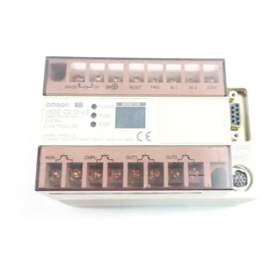
Section V600-CAjA-Vj ID Controller V600-CAjA-Vj ID Controller 2-1-1 Nomenclature Front Panel Protective conductor terminal Reset input terminals Power supply terminals Monitor Unit connector Operation indicators V600-CAjA-Vj ID Controller Error output terminals Open terminals (do not use) Note Where there is no reference to the “V600-CA8A-V2 only” or the “V600-CA9A-V2 only”... -
Page 12: Specifications
Section V600-CAjA-Vj ID Controller Side Panel R/W Head Connector Up to two R/W Heads can be connected. Parallel Interface Connector Used for communications with the PC. Use the connector provided as an acces- sory with the Unit when making the connection. (Refer to page 69 for details on interface connection.) PARALLEL I/0 HEAD 1... -
Page 13: External Input/Output Specifications
Section V600-CAjA-Vj ID Controller Characteristics Parameter Specifications Memory backup Capacitors used for backup, and storage of statistical errors and latest errors are effective for 20 days after Unit power is turned off (at ambient temperature of 25°C). Refer to the plot given below for the relationship between ambient temperature and memory backup time. -
Page 14: Outer Dimensions
Four, 4.3 dia. mounting holes 2-1-5 Communications Specifications OMRON’s original parallel interface built into the V600-CA8A-Vj/9A-Vj ID Controller enables communications with a general-purpose PC. The parallel interface includes input and output sections, connected separately to the PC Input Unit and Output Unit. -
Page 15: Input/Output Specifications
Section V600-CAjA-Vj ID Controller 2-1-6 Input/Output Specifications • Use a bi-directional input unit for the PC. • The ID Controller input section common terminal (I COM) and output section common terminal (O COM) are not connected internally. Input Section Input Unit 24 VDC: +10% (including ripple component), –15% On voltage 19 V min. -
Page 16: Monitor Unit
Section Monitor Unit Monitor Unit 2-2-1 General Specifications General specifications are the same as those for the ID Controller. Note that the operating ambient temperature must be in the range 0°C to 40°C. 2-2-2 Dimensions 80.6 120.6 22.6 Refer to Section 4 Monitor Unit Operation for information on the functions and operating procedures of the Monitor Unit. -
Page 17: Communications With Programmable Controller
SECTION 3 Communications with Programmable Controller This section provides procedures and formats required for communications with the Programmable Controller. Program examples are also provided. Data Carrier Motion and Command Conditions ....... . . 3-1-1 Communications Control Procedure . -
Page 18: Data Carrier Motion And Command Conditions
Data Carrier Motion and Command Conditions 3-1-1 Communications Control Procedure OMRON’s unique host communications control procedure enables the ID Con- troller to communicate with a general-purpose PC via the PC’s I/O Unit. • The ID Controller has access to the PC via a total of 32 points (i.e., 21 input and 11 output points of the ID Controller are used). -
Page 19: Data Carrier Motion And Command Conditions
Data Carrier Motion and Command Conditions Section 3-1-2 Read and Write Functions Command Processing The read/write functions are used for communications when the DC is station- ary. Thus, before using these commands, it is necessary to check that the DC is at a specific position. -
Page 20: Automatic Read/Write Function
Data Carrier Motion and Command Conditions Section 3-1-3 Automatic Read/Write Function Command Processing Under the automatic commands, the ID Controller does not return a response until the DC comes close to the specified R/W Head. This means that the com- munications path to the PC remains in the busy condition until the response is returned, and the IBM PC/AT or compatible cannot send commands specifying the other R/W Head of the same ID Controller. -
Page 21: Simultaneous Processing Of Commands
Data Carrier Motion and Command Conditions Section 3-1-4 Simultaneous Processing of Commands The ID Controller can have two R/W Heads connected to it, and communications can be conducted with them independently. (DC) (ID Controller) (DC) Busy Auto read Not close condition (Head 1) (Head 1) -
Page 22: Data Carrier Memory Map
Data Carrier Memory Map Section 3-1-5 Command Processing in Busy Condition The ID Controller accepts commands from the PC and remains in the busy condition from that time until a DC approaches (until it can execute a command). If a new command is sent to the ID Controller for the same Head while the ID Controller is in the busy condition, the new command replaces the old command which becomes invalid. -
Page 23: Memory Map
Data Carrier Memory Map Section 3-2-1 Memory Map DC with a Memory Capacity of 256 Bytes or Less Data Address Write protected area 0 0 0 0 0 0 0 1 0 0 0 2 0 0 0 3 User area 1 byte DC with a Memory Capacity of More Than 256 Bytes Data... -
Page 24: Write Protect Function
Data Carrier Memory Map Section Note 1. The last two digits of the year is used. For example, 92 for 1992. 2. The month is represented by two digits. For example, 03 for March and 10 for October. Example In the case of September 1992, the bits are as follows: Address 0000 0001... - Page 25 Data Carrier Memory Map Section Example 2 All bytes from 0001 through 00FD will be write-protected when bit 7 is ON and the end address is set to 00. Address 0000 0001 É É É É É É É É É É É É Write-protected area É...
- Page 26 Data Carrier Memory Map Section When the addresses are not write protected, the conditions of the addresses are as follows: Address Upper bits Lower bits 0002 0003 0004 0005 Examples Several examples of write-protect settings are listed below. These examples are for a 2K-byte DC, for an 8K-byte DC simply replace 07FF with 1FFF.
-
Page 27: Sram Data Carrier Battery Check
Data Carrier Memory Map Section 4. If start address is greater than the end address (start address > end ad- dress), the write-protected area will wrap through 0006, so that addresses from 0006 through the end address,and from the start address through 07FF will be write-protected. -
Page 28: Communications Methods
Communications Methods Section 3-2-5 EEPROM Batteryless Data Carrier Check Unlike the V600-CA1A-Vj or V600-CA2A-Vj Serial Interface ID Controller, the MDL command (which manages the number of overwriting operations) cannot be used with the DC that incorporates EEPROM (batteryless-type DC). To keep a record of the number of overwriting operations on the Parallel Interface ID Controller, the user should use the write or auto write command to increase the number of overwriting operations. -
Page 29: Command/Response Format
Command/Response Format Section 3. When a communications error is recognized, communications are turned off. Note 1. A page that the ID Controller has access to must be set with DIP switch 1 of the ID Controller. The setting will be effective when the power is turned on. Any setting altered with DIP switch 1 after the power is turned on will not be effective. -
Page 30: Response Format
Command/Response Format Section Example: In this example, the DC’s address 0318 is specified for command processing. 3 4 5 6 7 8 Address Lines: Write Data Lines Eight lines (WD0 to WD7) are used to specify the data to be written in the case of write processing. -
Page 31: Command And Response Timing
Command and Response Timing Section 2. The ERR line is not OFF, which informs the PC that local communications have been performed normally. 3. Line RS1 or RS2 of the ID Controller is ON, which informs the PC that the DC write operation has been completed. -
Page 32: Response Output Timing
Command and Response Timing Section Operation 1, 2, 3... 1. The input signals (CEXE, C0 to C2, AD0 to AD7, and WD0 to WD7) will be retrieved following an interval of td(1) after the HS line changes so that the input signals can be retrieved after they are fixed. -
Page 33: Operation Timing Chart
Command and Response Timing Section b) The cycle of the HS change (t ) must be 10 ms or more, taking the I/O delay of the PC and the internal processing time of the ID Controller into consideration. 3-5-3 Operation Timing Chart The following is an example of transmission of an auto read command to Head 1 and a write command to Head 2. -
Page 34: Communications Time
Communications Time Section 4. In synchronization with the next HS line change, after an interval of td(3), line RS1 will be turned OFF. Note a) t DC wait time (t ) + command execution time (t ) + HS line wait time (t ) + td(2) If an auto command is to be executed, the DC wait time (t... -
Page 35: Program Examples
Program Examples Section Program Examples This section gives examples of SYSMAC C500 auto read and auto write pro- grams. Example of PC and ID Controller Connections ID Controller Output Unit Contact No. Channel No. Signal Name Clock signal Send destination Head no. Command execution CEXE C2 = 0: Head 1... -
Page 36: Program Examples
Program Examples Section 3-7-1 Example of One-byte Auto Read Operation When read start contact goes on, data is read from DC address 00, and stored in DM 100. 0208(RS1) Capture of response data into DM100 ANDW(34) #00FF DM 100 0210(ERR) Normal termination contact 0210(ERR) Abnormal termination contact... -
Page 37: Example Of One-Byte Auto Write Operation
Program Examples Section 3-7-2 Example of One-byte Auto Write Operation When write start contact goes on, data $51 is written to DC address 10. 0208(RS1) ANDW(34) Stored of response data into DM100 #00FF DM 100 0210(ERR) Normal termination contact 0210(ERR) Abnormal termination contact Write start contact DIFU(13) -
Page 38: Example Of Five-Byte Auto Read Command
Program Examples Section 3-7-3 Example of Five-byte Auto Read Command Five bytes of data is read starting from DC address 00, and stored in DM 100 to DM 104. 0208(RS1) ANDW(34) Indirect address specification (Store read data to DM100 to 104) #00FF *DM 001 0210(ERR) -
Page 39: Example Of Five-Byte Auto Write Command
Program Examples Section 3-7-4 Example of Five-byte Auto Write Command Five bytes of data from DM050 to 054 is written into DC addresses 10 to 14. 0208(RS1) Store response data to DM100 ANDW(34) #00FF DM 100 0210(ERR) Normal termination contact 1003 0210(ERR) 1004... - Page 40 Program Examples Section 1003 1000 Write continuation contact Increment write data storage address INC(38) DM 001 Increment write address INC(38) DM 000 CMP(20) DM 000 #0014 6305(>) Write termination contact 1001 1004 1002 Retry contact at abnormal termination (Normally OFF contact) 6114 Select Head 1 0002(C2)
-
Page 41: Monitor Unit Operation
SECTION 4 Monitor Unit Operation This section provides the commands and procedures required for Monitor Unit operations. Using Monitor Unit (V600-P01) ..........4-1-1 Monitor Unit Functions . -
Page 42: Using Monitor Unit (V600-P01)
Using Monitor Unit (V600-P01) Section Using Monitor Unit (V600-P01) The Monitor Unit is a monitoring tool mounted on the ID Controller. It can be used during system startup to check communications with the DC, to read or write data to the DC, and to read any error messages. 4-1-1 Monitor Unit Functions The Monitor Unit has the following functions which are executed in the MON- ITOR Mode. -
Page 43: Mounting The Monitor Unit
Using Monitor Unit (V600-P01) Section 4-1-2 Mounting the Monitor Unit The Monitor Unit is attached by sliding the ID Controller connector cover in the direction of the arrow on the cover. Press the four tabs on the back of the Monitor Unit down until they lock to make sure that it is mounted properly and securely. -
Page 44: Preparations For Operations In Monitor Mode
Using Monitor Unit (V600-P01) Section Operation Keys These are used to select functions and execute operations and also include numerical keys. Key Designations Function selection TEST ADRS DATA Operation WRITE WRITE READ PESET Numbers English/Japanese Character Selection Note There is a beeper in the ID Controller, which activated when a mistake is made in the Monitor Unit key operations, or when read or write operations cannot be per- formed (because DC is not present or other reasons). -
Page 45: Monitor Unit Operation List
Monitor Unit Operation List Section DATA Setting For a write operation, one byte of the specified data is written to the DC in the area defined by the start and end addresses. Note 1. Data setting is not required for an operation test with the test read or test auto read command to check the relationship of the position. -
Page 46: Data Read And Write Operations
Monitor Unit Operation List Section 4-2-2 Data Read and Write Operations Operation Description Basic operation procedure Page mode Read (READ) Data from any desired Address Job spec READ setting address is read from Decrement address, and read READ Step write One byte of data is Address WRITE... -
Page 47: Basic Operations
Basic Operations Section Basic Operations 4-3-1 Changing Operation Mode The following describes how to switch the ID Controller operation mode. By pressing the Left or Right Arrow Key when MONITOR is displayed, the English or Japanese display can be selected. The selected display will be on hold until the Left or Right Arrow Key is pressed again. -
Page 48: Job Specification (Job)
Basic Operations Section 4-3-2 Job Specification (JOB) This enables setting of the Head number and page number for data reading, writing and testing in the MONITOR Mode. Operation Procedure The following is an example specifying R/W Head 1 and Page 2 (DC memory area addresses 0200 to 02FF). -
Page 49: Address Setting (Adrs)
Basic Operations Section 4-3-3 Address Setting (ADRS) This enables the setting of the start address for data reading, writing, and test- ing. Operation Procedure Start address: 5A in this example aXXdXX RESET a_ dXX ADRS a5_dXX a5AdXX a5AdXX a5AdXX 1, 2, 3... 1. -
Page 50: Data Specification (Data)
Basic Operations Section 4-3-4 Data Specification (DATA) When writing data to the DC, specify the data in two hexadecimal digits in the range 00 to FF. Operation Procedure The following procedure is an example showing how to specify 3C as the data. aXXdXX RESET aXXd... -
Page 51: Data Read And Write Operations
Data Read and Write Operations Section Data Read and Write Operations These operations are used to read data from or write data to the DC in the offline condition. Before executing these operations, check that the R/W Head is con- nected, and check for the presence or absence of the DC. - Page 52 Data Read and Write Operations Section Note 1. If the INC/DEC Key is pressed, and the address exceeds the 00 to FF range: Page 2 Page 2 2. If the address is FF when the INC Key is pressed, the setting returns to ad- dress 00 of the same page.
-
Page 53: Step Write
Data Read and Write Operations Section 4-4-2 Step Write This is used to write one byte of data to the desired DC address. Operation Procedure Job specification Head no. setting Page no. setting Address setting ADRS aFEd_ DATA aFEd3 aFEd3C WRITE S WRITE? SWaFEd3C... -
Page 54: Continuous Write (Write2)
Data Read and Write Operations Section 4-4-3 Continuous Write (WRITE2) This is used to write the same one byte of data to a continuous series of DC ad- dresses. Operation Procedure The example shows the procedure for writing 0F into locations 50 to 5F. Job specification Head no. -
Page 55: Operation Test (Test)
Operation Test (TEST) Section 2. Specify the end address. When either of the horizontal cursor keys is pressed, the display changes to the end address. Note a) Ensure that the start address does not exceed the end address. b) In the case of a DC with SRAM, page 0 addresses 00 and 01 are reserved for registration of the production date (year, month, day), and data cannot be written in this area. -
Page 56: Test Read
Operation Test (TEST) Section Test Menu Selection MONITOR Monitor mode switch a00d00 RESET TEST 1 4 TEST Test read Test write In the test mode, the selected command is executed repeatedly. Test auto read Test auto write 1, 2, 3... 1. - Page 57 Operation Test (TEST) Section If the start address is set, only the data in that location is displayed. While the read test is in progress, the data in the display flashes every second, and the ID Controller Head number display indicator also flashes every second. Note When an error occurs in communications between the DC and a R/W Head, the error code is displayed (see page 78).
- Page 58 Operation Test (TEST) Section 2. Specify the write end address. If the start address exceeds the end address, then data is written only to the start address location. 3. Specify the data. 4. When the TEST Key is pressed, the test menu is shown on the display. 5.
- Page 59 Operation Test (TEST) Section 4-5-4 Test Auto Write One byte of data is written repeatedly to any memory area defined by specified start and end addresses from the DC while it is in motion. The step number of the send data can be set to any value in the range 1 to FF (256 bytes maximum), enabling a total communications test checking relationships between installa- tion positions, speeds, and other parameters.
-
Page 60: Reading Error Information (Err)
Reading Error Information (ERR) Section 5. Press Key 4 to select auto write, and then TAW is shown on the display. Head 1 indicator lights now. 6. When the DC enters the operation range, the specified data is sent to the memory area defined by the start and end addresses, and Head 1 indicator flashes while processing occurs. -
Page 61: Reading Error Data
Reading Error Information (ERR) Section 2. When the ERR Key is pressed, the error mode selection menu appears on the display. Use numerical keys 1 to 4 to select the error mode. 4-6-1 Reading Error Data The ID Controller has a memory area designated for data storage of errors oc- curring in the RUN Mode. -
Page 62: Reading Error Statistics
Reading Error Information (ERR) Section Note Error data (up to 30 items) and error statistics are stored in the ID Controller RAM. Data storage is supported by a maintenance-free back-up capacitor, and data is preserved for approximately 20 days (at 25°C) after power to the ID Con- troller is turned off. -
Page 63: Clear Error Data
Reading Error Information (ERR) Section 3. When the INC Key is pressed, the number of error occurrences for the first error code 10 is displayed. The maximum number of occurrences that can be counted for each error code is 999. 4. -
Page 64: Clear Error Statistics
Reading Error Information (ERR) Section 4-6-4 Clear Error Statistics This procedure is used to clear error statistics from memory, and to specify the new date (year, month, day) to start collecting statistics. Here we take August 10, 1988, as an example. Operation Procedure ERROR1 4 RESET... -
Page 65: Installation And Wiring
SECTION 5 Installation and Wiring This section provides installation and pre-operation setting procedures. Installation Environment ........... 5-1-1 Location . -
Page 66: Installation Environment
ID Controller Installation Section Installation Environment The V600-CA8A-Vj/9A-Vj ID Controller is a high-reliability control system that is resistant to variations in environmental conditions. Nevertheless, it is im- portant to observe the following precautions during installation to increase reli- ability and ensure that all system functions can be used to the utmost. 5-1-1 Location Do not install the ID Controller in locations subject to the the following conditions. -
Page 67: Din Rail Attachment
Spacer Note: Take DIN rail height into consideration. DIN Rail PFP-100N2 (made by OMRON Co.) 1, 2, 3... 1. When attaching the ID Controller to a DIN rail, first attach at A, then push in direction B to mount the ID Controller. -
Page 68: Connecting And Disconnecting R/W Head Connector
Connecting and Disconnecting R/W Head Connector Section Connecting and Disconnecting R/W Head Connector 5-3-1 Connection Procedure 1, 2, 3... 1. Hold the rubber molded section of the connector and insert the cable con- nector by fitting it into the key groove. 2. -
Page 69: Wiring Procedures
Wiring Procedures Section Wiring Procedures 5-4-1 Power Supply and Ground Line Wiring The ID Controller conforms to IEC1010-1, EN61010-1, UL3101 and CSA1010-1. Therefore, field wiring is readily available. Insulated transformer Breaker AC power supply: 100 to 240 VAC, 50/60 Hz Class 3 ground Note Use a Tokin GT-20601 filter or equivalent approved by TÜV or VDE. -
Page 70: Input/Output Line Wiring Precautions
Wiring Procedures Section 5-4-2 Input/Output Line Wiring Precautions Reset Signal Input • Take sufficient care to ensure that the input voltage does not exceed the maxi- mum applied voltage (26.4 V). Exceeding the permissible voltage level will damage the equipment. •... -
Page 71: Wiring Processing Precautions
Wiring Procedures Section 5-4-4 Wiring Processing Precautions Applying excessive external forces to connectors while they are connected to the system can cause damage to the connectors and internal PCBs, or cause cable wiring disconnections. Thus, it is important to provide at least 10 cm of space under the ID Controller to protect the connectors from external forces originating from the right or left. -
Page 72: Page Number Settings
Page Number Settings Section Page Number Settings This section describes the procedure for setting the page number in the DC memory area from which data is to be read or to which data is to be written. The host will have access to only the specified page area. Remove the connector cover and set the DIP switches as shown below. -
Page 73: Connecting Parallel Interface
Connecting Parallel Interface Section Connecting Parallel Interface Use the connector provided as an accessory as the communications connector. The user must provide the connecting cable. At ID Controller Connecting cable Recommended cable: UL2464-40X28AWG-Y-GRA (Forty 0.38-mm diameter conductors, cable diameter: 10.5 mm) MR-50F Plug MR-50L Hood (Honda Tsushin Kogyo)*... - Page 74 Connecting Parallel Interface Section V600-CA9A-Vj (NPN Output) Pin no. Signal Pin no. Signal Pin no. Signal name name name ICOM1 CEXE ICOM2 ICOM3 OCOM1 OCOM2 Output Section Signal Names and Descriptions V600-CA8A-Vj (PNP Output) Signal name Abbreviation Pin no. Description COMMON OCOM1 RD0 to RD7 common pins...
- Page 75 Connecting Parallel Interface Section V600-CA9A-Vj (NPN Output) Signal name Abbreviation Pin no. Description COMMON OCOM1 RD0 to RD7 common pins READ DATA Response data output – Read: Read data – Write: End code – Error: Error code COMMON OCOM2 RS1. RS2, and ERR common pins RESPONSE Response data output STROBE...
-
Page 76: Connector Assembly
Connecting Parallel Interface Section Note 1. ICOM1 (pin 4), ICOM2 (pin 7), and ICOM3 (pin 10) are connected internally. 2. Do not use pins not listed in the output section and input section signal-pin tables above (pins 1, 2, 11, 16, to 19, 28, 33, 34, and 43). 5-6-2 Connector Assembly Plug 20 to 25 mm... - Page 77 Connecting Parallel Interface Section To remove the connector, completely unscrew the two lock screws, and take out the protruding section of the connector hood by hand and pull it straight out. If it is difficult to remove, hold the ID Controller down with one hand and pull care- fully on the connector with the other.
-
Page 78: Diagnosis And Maintenance
SECTION 6 Diagnosis and Maintenance This section provides diagnosis and maintenance procedures as well as solutions to possible problems and abnormalities. Test Operation ............6-1-1 Checklist . -
Page 79: Test Operation
Test Operation Section Test Operation 6-1-1 Checklist Check the following items before performing the test operation. Check items Checks Page Power supply and I/O line Has wiring been done correctly? connections Are the terminal screws loose? DIP switch settings Have page settings been made correctly? R/W Head connection Are R/W Heads connected correctly? DC positioning... -
Page 80: Diagnostic Functions
Diagnostic Functions Section 6-1-3 Using Monitor Unit for Offline Test The Monitor Unit can be used to test communications between the R/W Heads and the DCs with the ID Controller disconnected from the host computer. Use this test to check the installation positions and speeds prior to performing test operations (see Appendix C Offline Test and Auto Read/Auto Write). -
Page 81: Error Lists
Error Lists Section Operation Continuation When an abnormality occurs in communications between the ID Controller and Abnormality the host computer or a R/W Head, the ERROR indicator lights. Up to 30 files of abnormality data are stored, and if this number is exceeded, old abnormality data is erased from the beginning to make room for the new data. -
Page 82: Dealing With Abnormalities
Dealing with Abnormalities Section 6-3-2 System Errors Error Name Error Description and cause code message Power P OFF CMD Power is disconnected during command After applying power once disconnection execution. again, execute the command during command again. processing Power P OFF WT Power was disconnected during disconnection execution of a write or auto write... -
Page 83: Maintenance And Inspections
Maintenance and Inspections Section Improving Ground Other Other equipment Controller equipment controller ground Dealing with Power Supply Noise Controller Power supply Twist lines and ensure that Noise filter they are not parallel to other power lines Note Use a Tokin GT-20601 filter or equivalent approved by TÜV or VDE. Then ground its ground terminal. -
Page 84: Inspection Parameters
Maintenance and Inspections Section 6-5-1 Inspection Parameters Inspection Inspection description Criteria Remarks parameters Line voltage variation (i) Determine whether it’s within standards Line voltage should be Tester by checking power supply terminal within specified range. strip. (ii) Is there frequent instantaneous power Voltage variation should Power drops or sudden voltage fluctuations? -
Page 85: Troubleshooting
Troubleshooting Section Troubleshooting When abnormalities occur, it is important to make the following checks to deter- mine completely the nature of the problem, determine whether there is any pos- sibility of reoccurrence, and to find out if there is any relation to other devices. 6-6-1 Main Troubleshooting Flowchart START Handle problems by first making a general check... -
Page 86: System Connection Troubleshooting Flowchart
Troubleshooting Section 6-6-2 System Connection Troubleshooting Flowchart START connector cable connections Turn Power on Connect properly. Not lit “POWER” indicator? “ERROR” indicator? Is specified voltage (“STOP” indicator) supplied? Not lit Supply specified voltage “STOP” indicator Not lit Is reset input Mount Monitor Unit Turn reset input off MONITOR... -
Page 87: Host Communications Troubleshooting Flowchart
Troubleshooting Section 6-6-3 Host Communications Troubleshooting Flowchart START Is connector wiring okay? Repair connector wiring Are host operations okay? Correct host program or replace PC... -
Page 88: Local Communications Troubleshooting Flowchart
Troubleshooting Section 6-6-4 Local Communications Troubleshooting Flowchart START Can Monitor Unit be used? Mount Monitor Unit, Do not mount Monitor switch to monitor mode, Unit, turn power on, and turn power on and connect to host Execute test AW Send AW command Does Head indi- cator go from on to off? -
Page 89: External Environment Troubleshooting Flowchart
Troubleshooting Section (Continued) (Continued) R/W Head E7C? Replace R/W Head Is write DC OK? protect setting E7D? Clear write protect Replace DC Is distance communica- DC OK? between R/W Head and DC tions OK? Replace DC Adjust distance Normal termination? Replace Unit 6-6-5 External Environment Troubleshooting Flowchart START... -
Page 90: A Standard Models
Appendix A Standard Models ID Controller and System Components Product Specification Model number Remarks ID Controller Serial interface, 100 to 240 ––– V600-CA8A-Vj (PNP VAC power supply output) V600-CA9A-Vj (NPN output) Monitor Unit ––– V600-P01 ––– Communications connector Connector plug MR-50F A connector plug and connector hood are... -
Page 91: B Auto Read/Auto Write
Appendix B Auto Read/Auto Write Use of Auto Read and Auto Write Commands In general, read and write commands are used while DCs are stationary. Auto commands are used while DCs are in motion. Read and Write Commands • Communications distance can be greater than when DC is in motion, and so accurate communications can be performed. - Page 92 Appendix B Auto Read/Auto Write Application Example of Command Item Application Description Note Command Transmits next auto command after – When DC passes – Keep transportation transmission by response is returned. through the speed constant. timer communications area of – Valid only for systems R/W Head at fixed where communication is intervals.
-
Page 93: C Conformity To Standards
Appendix C Conformity to Standards UL (Underwriters’ Laboratories Inc.) UL3101 Listing Mark File No. E41515 CSA (Canadian Standard Association) CSA1010.1 Listing Mark File No. LR46463 EC Directives We hereby declare that the following products are in conformity with the requirements of the EC Directives listed below: Identification System V600-CA8A/9A-V2 ID Controllers... - Page 94 Appendix C Conformity to Standards Technical Data Intended Environment: Industrial Type designation: V600-CA8A/9A-V2 Host interface: Parallel interface CA8A-V2: PNP, CA9A-V2: NPN Number of Read/Write Heads connectable: 2 channels Rated power supply voltage: 100 to 240 VAC, 50/60 Hz Acceptable power supply voltage: 85 to 264 VAC Power consumption: 35 VA max.
- Page 95 Appendix C Conformity to Standards • Read/Write Heads V600-H j j-j I II III IV I – V600: Inductive Identification System II – H: Read/write head III – j: Shape – 0 or 1 Square type – 5 Cylindrical type IV –...
-
Page 96: Revision History
Revision History A manual revision code appears as a suffix to the catalog number on the front cover of the manual. Cat. No. Z045-E1-3 Revision code The following table outlines the changes made to the manual during each revision. Page numbers refer to the previous version.
Need help?
Do you have a question about the V600-CA8A-V Series and is the answer not in the manual?
Questions and answers