
Related Manuals for Allied Telesis AT-MC103SC/FSx


Summary of Contents for Allied Telesis AT-MC103SC/FSx
- Page 1 AT-MC101XL AT-MC102XL AT-MC103XL AT-MC103LH AT-MC103SC/FSx AT-MC103ST/FSx Fast Ethernet Media Converters Version 3 Installation Guide PN 613-10771-00 Rev F...
- Page 2 Copyright 2003 Allied Telesyn, Inc. 960 Stewart Drive Suite B, Sunnyvale CA 94086 USA All rights reserved. No part of this publication may be reproduced without prior written permission from Allied Telesyn, Inc. Ethernet is a registered trademark of Xerox Corporation. All other product names, company names, logos or other designations mentioned herein are trademarks or registered trademarks of their respective owners.
-
Page 3: Electrical Safety And Emission Compliance
Electrical Safety and Emission Compliance Standards: This product meets the following standards. U.S. Federal Communications Commission Declaration Of Conformity Manufacture Name: Allied Telesyn, Inc. Manufacture Address: 960 Stewart Drive, Suite B Sunnyvale, CA 94086 USA Manufacture Telephone: 408-730-0950 Declares that the Product: Fast Ethernet Media Converters Model Numbers: AT-MC101XL, AT-MC102XL,... - Page 4 Electrical Safety and Emission Compliance Industry Canada This Class B digital apparatus meets all requirements of the Canadian Interference-Causing Equipment Regulations. Cet appareil numérique de la classe B respecte toutes les exigences du Règlement sur le matériel brouilleur du Canada. RFI Emission EN55022 Class B Immunity...
- Page 5 AT-MC100 Series Installation Guide Importante: O Anexo A contém advertências de segurança traduzidas para instalar este equipamento. Quando vir o símbolo ! , leia a advertência de segurança traduzida no seu idioma no Anexo A. Importante: El Apéndice A contiene mensajes de seguridad traducidos para la instalación de este equipo.
-
Page 7: Table Of Contents
Table of Contents Electrical Safety and Emission Compliance..........iii Table of Contents ..................vii Welcome to Allied Telesyn ................ix Where to Find Web-based Guides ..............ix Document Conventions ..................ix Contacting Allied Telesyn Technical Support........... x Online Support .................... x Telephone Support .................. - Page 8 Chapter 3 Troubleshooting .................... 15 Troubleshooting Guidelines ................15 Loopback Test ....................17 Appendix A Technical Specifications ................19 Physical ......................19 Environmental ....................19 Electrical Rating ....................19 Agency Certifications..................20 Fiber Optic Port Specifications ................ 20 Appendix B Translated Electrical Safety and Emission Information.....
-
Page 9: Welcome To Allied Telesyn
Welcome to Allied Telesyn This guide contains instructions on how to install an AT-MC100 Series Fast Ethernet Media Converter. Where to Find Web-based Guides The Allied Telesyn web site at www.alliedtelesyn.com offers you an easy way to access the most recent documentation, software, and technical information for all of our products. -
Page 10: Contacting Allied Telesyn Technical Support
Welcome to Allied Telesyn Contacting Allied Telesyn Technical Support You can contact Allied Telesyn technical support online or by telephone or e-mail. Online Support You can request technical support online by accessing the Knowledge Base at http:\\kb.alliedtelesyn.com. You can use the Knowledge Base to submit questions to our technical support staff and review answers to previously asked questions. -
Page 11: Returning Products
AT-MC100 Series Installation Guide Returning Products Products for return or repair must first be assigned a Return Materials Authorization (RMA) number. A product sent to Allied Telesyn without a RMA number will be returned to the sender at the sender’s expense. To obtain an RMA number, contact Allied Telesyn’s Technical Support at one of the following locations: North America... -
Page 12: Tell Us What You Think
Welcome to Allied Telesyn Tell Us What You Think If you have any comments or suggestions on how we might improve this or other Allied Telesyn documents, please fill out the General Enquiry Form online. This form can be accessed by selecting “Contact Us” from www.alliedtelesyn.com. -
Page 13: Overview
Chapter 1 Overview The AT-MC100 Series Fast Ethernet Media Converters include the following models: AT-MC101XL AT-MC103SC/FS3 AT-MC102XL AT-MC103ST/FS3 AT-MC103XL AT-MC103SC/FS4 AT-MC103LH AT-MC103ST/FS4 The AT-MC100 Series Fast Ethernet Media Converters are designed to extend the distance of your network by interconnecting LAN devices that are physically separated by large distances. -
Page 14: Key Features
Overview Table 1 lists the maximum operating distances for the media converters. Table 1 Maximum Operating Distances Model Type of Connector Maximum Operating Distance 100Base-FX 100Base-TX 100Base-FX 100Base-TX AT-MC101XL RJ-45 2 km (1.2 mi) 100 m (328 ft) AT-MC102XL RJ-45 2 km (1.2 mi) 100 m (328 ft) AT-MC103XL... -
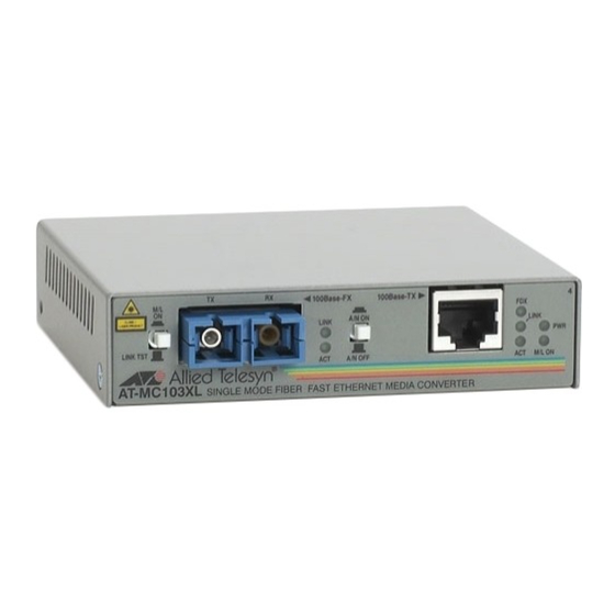
Page 15: Status Leds
AT-MC100 Series Installation Guide Status LEDs Table 2 defines the media converter’s LEDs. Table 2 Status LEDs State Color Description Green Power is applied to the media converter. Green A link has been established on the port. Green Data is being received on the port. Green The port is operating in full-duplex mode. -
Page 16: Link Test/Missinglink Button
Overview Link Test/MissingLink Button The Link Test/MissingLink button allows you to perform a link test on the ports on the media converter. This button also allows you to activate the MissingLink feature on the unit. Both features are describe in the following section. -
Page 17: Auto-Negotiation Button
AT-MC100 Series Installation Guide The value to this type of network monitoring and fault notification is that some hubs and switches can be configured to take a specific action in the event of the loss of connection on a port. In some cases, the unit can be configured to seek a redundant path to a disconnected node or send out a trap to a network management station, and so alert the network administrator of the problem. -
Page 18: External Ac/Dc Power Adapter
Overview There is one situation where it may be necessary to disable the auto- negotiation feature, and that is to prevent a mismatch from occurring between the duplex modes of the end-nodes. For example, Figure 2 shows two units that have been connected with a media converter. Unit 1 is a repeater that is capable of operating in half-duplex mode only. -
Page 19: Network Topologies
AT-MC100 Series Installation Guide Network Topologies The AT-MC100 Series Media Converters can be used in two different types of topologies: standalone and back-to-back. Both topologies are described below. Standalone Topology Figure 3 illustrates a standalone topology where two AT-8224XL switches have been interconnected with an AT-MC102XL media converter. -
Page 20: Back-To-Back Topology
Overview Back-to-Back Topology Figure 4 illustrates two media converters in a back-to-back configuration. AT-8224XL AT-MC103SC/FS3 STATUS RS-232 PORT ACTIVITY TERMINAL PORT 10BASE-T / 100BASE-TX 10BASE-T / 100BASE-TX SWITCH FAST ETHERNET CLASS 1 100Base-FX 100Base-TX LASER PRODUCT DO NOT STARE INTO BEAM A/N ON A/N OFF MDI-X... -
Page 21: Installing The Media Converter
Chapter 2 Installing the Media Converter Verifying the Package Contents Make sure the following items are included in your package. If any item is missing or damaged, contact your Allied Telesyn sales representative for assistance. One AT-MC100 Series Fast Ethernet Media Converter Four protective feet (for desktop use only) An external AC/DC power adapter This installation guide... - Page 22 Installing the Media Converter Table 3 100Base-TX Twisted Pair Port Cabling Specifications Cable Type Maximum Operating Distance Shielded or unshielded Category 5 or better 100 m (328 ft) Table 4 100Base-FX Fiber Optic Port Specifications (Full-duplex) Model Type of Fiber Optic Maximum Maximum Allowable Cable...
-
Page 23: Reviewing Safety Precautions
AT-MC100 Series Installation Guide Table 5 100Base-FX Fiber Optic Port (Half-duplex) Number of Media Converters Connected Devices Maximum Operating Distance One Media Converter Inline Switch to Switch 372 m (1,221 ft) Workstation to Switch 372 m (1,221 ft) Switch to Class I Repeater 137 m (450 ft) Switch to Class II Repeater 185 m (607 ft) -
Page 24: Installing The Media Converter
Installing the Media Converter Caution All Countries: Install this product in accordance with local and National Electric Codes. Installing the Media Converter The following procedure explains how to install an AT-MC100 Series Media Converter. To install the media converter, perform the following procedure: Remove all equipment from the package and store the packaging material in a safe place. - Page 25 AT-MC100 Series Installation Guide Set the Link Test/MissingLink button to LNK TST (OUT) position. Set the auto-negotiation feature as follows: If both end-nodes will use auto-negotiation to determine the duplex mode, or if both are pre-set to operate with the same duplex mode, such as half-duplex, set the switch to the A/N ON (IN) position.
-
Page 26: Warranty Registration
Installing the Media Converter 11. Set the MDI/MDI-X button as follows: If you are connecting a workstation to the 100Base-TX port, set the MDI/MDI-X button to the MDI-X (OUT) position. MDI-X is the default position. If you are connecting a hub or a switch to the 100Base-TX port, set the MDI/MDI-X switch to the MDI (IN) position. -
Page 27: Chapter 3 Troubleshooting
Chapter 3 Troubleshooting Troubleshooting Guidelines Follow the guidelines below to test and troubleshoot the installation in the event a problem occurs. If the PWR LED is OFF, do the following: If the unit is installed on a desktop, check to be sure that the power adapter is securely connected to a power outlet and that the power adapter cable is securely connected to the back of the media converter. - Page 28 Troubleshooting If the LNK LED for the fiber optic port is OFF, do the following: Verify that then end-node connected to the port is ON and is operating properly. Check that the fiber optic cable is securely connected to the fiber optic port on the media converter and on the end-node.
-
Page 29: Loopback Test
AT-MC100 Series Installation Guide Loopback Test To check hardware reliability of the media converter, perform the following procedure: Power OFF the media converter by unplugging the power adapter from the wall outlet and from the back of the unit. Connect the RJ-45 twisted pair port to a 100Base port on the end-node and power ON the end-node. -
Page 31: Technical Specifications
Appendix A Technical Specifications Physical Dimensions: W x D x H 10.5 cm x 9.5 cm x 2.5 cm (4.125 in x 3.75 in x 1.0 in) Weight: 0.27 kg (0.60 lbs) Environmental Maximum Operating Temperature: 0° C to 40° C (32° F to 104° F) Maximum Storage Temperature: -20°... -
Page 32: Agency Certifications
Technical Specifications Agency Certifications EMI/RFI: FCC Class B, EN55022 Class B, VCCI Class B Electrical Safety: EN60950 (TUV), UL1950 ( CE Compliant Immunity: EN55024 VCCI Class B Fiber Optic Port Specifications Table 6 through Table 9 lists the specifications for the 100Base-FX fiber optic port. - Page 33 AT-MC100 Series Installation Guide Table 7 Fiber Optic Receiver Model Fiber Fiber Optical Type Optic Wavelength Receive Power (dBm) Diameter (microns) Min. Typical Saturation AT-MC101XL 50/125 or 1310 nm -31.8 -34.5 -14.0 62.5/125 AT-MC102XL AT-MC103XL 9/125 1310 nm -31.0 -31.0 -8.0 AT-MC103LH 9/125...
- Page 34 Technical Specifications Table 8 Fiber Optic Datalink (Continued) Model Fiber Minimum Average Minimum Maximum Type Power / Signal Distance Distance Link Loss Spec. Spec. Budget AT-MC103SC/FS3 9/125 SMF 33.00 dB 35.00 dB 15 km 75 km (9.4 mi) (46.5 mi) AT-MC103ST/FS3 AT-MC103SC/FS4 9/125 SMF...
-
Page 35: Translated Electrical Safety And Emission Information
Appendix B Translated Electrical Safety and Emission Information Important: This appendix contains multiple-language translations for the safety statements in this guide. Wichtig: Dieser Anhang enthält Übersetzungen der in diesem Handbuch enthaltenen Sicherheitshinweise in mehreren Sprachen. Vigtigt: Dette tillæg indeholder oversættelser i flere sprog af sikkerhedsadvarslerne i denne håndbog. - Page 36 Translated Electrical Safety and Emission Information Standards: This product meets the following standards. U.S. Federal Communications Commission Declaration Of Conformity Manufacture Name: Allied Telesyn, Inc. Manufacture Address: 960 Stewart Drive, Suite B Sunnyvale, CA 94086 USA Manufacture Telephone: 408-730-0950 Declares that the Product: Fast Ethernet Media Converters Model Numbers: AT-MC101XL, AT-MC102XL,...
- Page 37 AT-MC100 Series Installation Guide Industry Canada This Class B digital apparatus meets all requirements of the Canadian Interference-Causing Equipment Regulations. Cet appareil numérique de la classe B respecte toutes les exigences du Règlement sur le matériel brouilleur du Canada. RFI Emission EN55022 Class B Immunity EN50082-1 1997...
- Page 38 Translated Electrical Safety and Emission Information ! 12 All Countries: Install product in accordance with local and National Electrical Codes. Normen: Dieses Produkt erfüllt die Anforderungen der nachfolgenden Normen. Hochfrequenzstörung EN55022 Klasse B Störsicherheit EN50082-1 1997 Achtung: Für dieses Produkt sind abgeschirmte Kabel erforderlich, damit den Richtlinien für Emission und Interferenzschutz entsprochen wird.
- Page 39 AT-MC100 Series Installation Guide Standarder: Dette produkt tilfredsstiller de følgende standarder. Radiofrekvens forstyrrelsesemissionEN55022 Klasse B Immunitet EN50082-1 1997 Advarsel: Dette produkt skal bruges med afskærmede kabler for at overholde bestemmelserne vedrørende udstråling og støjimmunitet. Hvis det bruges med uafskærmede kabler, kan det blive påkrævet af brugeren at korrigere interferensproblemer for egen regning.
- Page 40 Translated Electrical Safety and Emission Information Eisen: Dit product voldoet aan de volgende eisen. RFI Emissie EN55022 Klasse B Immuniteit EN50082-1 1997 Waarschuwing: Om te voldoen aan de emissie- en immuniteitsnormen dient dit apparaat te zijn voorzien van afgeschermde kabels. Als het met niet-afgeschermde kabels wordt gebruikt, kan het zijn dat de gebruiker maatregelen moet treffen om interferentieproblemen voor eigen rekening op te lossen.
- Page 41 AT-MC100 Series Installation Guide Normes: ce produit est conforme aux normes de suivantes. Emission d'interférences radioélectriques EN55022 Classe B Immunité EN50082 - 1 1997 Avertissement: Il faut utiliser des câbles blindés pour ce produit afin de respecter les normes d’émission et d’immunité. Si l’utilisateur choisit d’utiliser des câbles non blindés, il sera peut-être contraint de prendre les mesures nécessaires pour corriger les problèmes d’interférences, ainsi que d’assumer le coût correspondant.
- Page 42 Translated Electrical Safety and Emission Information Standardit: Tämä tuote on seuraavien standardien mukainen. Radioaaltojen häirintä EN55022 Luokka B Kestävyys EN50082-1 1997 Varoitus: Tämä tuote vaatii suojattuja kaapeleita toimiakseen emissio- ja häiriönsietostandardien mukaisesti. Jostuotetta käytetään ilman suojattuja kaapeleita, käyttäjä voi joutua korjaamaan häirinnän aiheuttaman ongelman omallakustannuksellaan.
- Page 43 AT-MC100 Series Installation Guide Standard: Questo prodotto è conforme ai seguenti standard. Emissione RFI (interferenza di radiofrequenza) EN55022 Classe B Immunità EN50082-1 1997 Avvertenza: questo prodotto, se utilizzato con cavi schermati, è conforme alle norme sulle emissioni e sull’immunità. In caso di uso senza cavi schermati, l’utente può...
- Page 44 Translated Electrical Safety and Emission Information Sikkerhetsnormer: Dette produktet tilfredsstiller følgende sikkerhetsnormer. RFI stråling EN55022 Klasse B Immunitet EN50082-1 1997 Advarsel: Dette produktet må brukes med vernede kabler for å tilfredsstille emisjons- og fritakelsesstandarder. Dersom produktet brukes med uvernede kabler, må brukeren muligens rette forstyrrelsesproblemene for egen regning.
- Page 45 AT-MC100 Series Installation Guide Padrões: Este produto atende aos seguintes padrões. Emissão De Interferência De Radiofrequência EN55022 Classe B Imunidade EN50082-1 1997 Advertência: Este produto requer a utilização de cabos blindados para cumprimento dos standards de limites de emissão e imunidade. Se o produto for utilizado com cabos não blindados, o utilizador poderá...
- Page 46 Translated Electrical Safety and Emission Information Estándares: Este producto cumple con los siguientes estándares. Emisión RFI EN55022 Clase B Inmunidad EN50082-1 1997 Advertencia: Este producto exige cables protectores para ajustarse a las normas de emisión e inmunidad. Si se utiliza con cables sin protección, el usuario tendrá...
- Page 47 AT-MC100 Series Installation Guide Standarder: Denna produkt uppfyller följande standarder. Radiostörning EN55022 Klass B Immunitet EN50082-1 1997 Varning! Denna produkt kräver skärmade kablar för att uppfylla standardkraven för emission och immunitet. Om den används med oskärmade kablar kan användaren vara tvungen att vidta åtgärder på egen bekostnad för att åtgärda störningsproblemet.
Need help?
Do you have a question about the AT-MC103SC/FSx and is the answer not in the manual?
Questions and answers