Table of Contents
Advertisement
Advertisement
Table of Contents
Troubleshooting

Related Manuals for ABB IRB 4400


Summary of Contents for ABB IRB 4400
- Page 1 Product Specification IRB 4400 3HAC 5671-1 M98A / BW OS 3.2 / Rev. 1...
- Page 2 ABB Robotics Products AB´s written permission, and contents thereof must not be imparted to a third party nor be used for any unauthorized purpose. Contravention will be prosecuted. Additional copies of this document may be obtained from ABB Robotics Products AB at its then current charge.
-
Page 3: Table Of Contents
3.7 Maintenance and Troubleshooting ................. 40 3.8 Robot Motion......................41 3.9 External Axes ......................46 3.10 Inputs and Outputs....................47 3.11 Communication..................... 51 4 Specification of Variants and Options................53 5 Accessories ........................69 6 Index ..........................71 Product Specification IRB 4400 M98A/BaseWare OS 3.2... - Page 4 Product Specification IRB 4400 Product Specification IRB 4400 M98A/BaseWare OS 3.2...
-
Page 5: Introduction
Introduction 1 Introduction Thank you for your interest in the IRB 4400. This manual will give you an overview of the characteristics and performance of the robot. The IRB 4400 is a 6-axis industrial robot, designed specifically for manufacturing industries that use flexible robot-based automation. The robot has built-in process ware, an open structure that is specially adapted for flexible use, and can communicate extensively with external systems. - Page 6 The programming language is described in the RAPID Reference Manual. The Product Manual describes how to install the robot, as well as maintenance procedures and troubleshooting. The Product Specification RobotWare describes the software options. Product Specification IRB 4400 M98A/BaseWare OS 3.2...
-
Page 7: Description
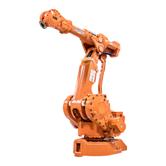
Axis 4 Axis 6 Axis 3 Axis 2 Axis 1 Figure 1 The IRB 4400 manipulator has 6 axes. Teach pendant Operator´s panel Mains switch Disk drive Figure 2 The controller is specifically designed to control robots, which means that optimal performance and functionality are achieved. -
Page 8: Safety/Standards
A delayed stop gives a smooth stop. The robot stops in the same way as at a normal program stop with no deviation from the programmed path. After approx. one second the power supplied to the motors shuts off. Product Specification IRB 4400 M98A/BaseWare OS 3.2... -
Page 9: Operation
All information, including the complete programming language, is in English or, if preferred, some other major language. (For a list of languages, see Product Specification RobotWare.) Product Specification IRB 4400 M98A/BaseWare OS 3.2... - Page 10 - Service and installation Operator’s panel Motors On button Operating mode selector and indicating lamp Emergency stop Duty time counter Figure 5 The operating mode is selected using the operator’s panel on the controller. Product Specification IRB 4400 M98A/BaseWare OS 3.2...
-
Page 11: Installation
The configuration can be stored on a diskette and/or transferred to other robots that have the same characteristics. All the versions of IRB 4400 are designed for floor mounting except one version for shelf-mounting. Depending on robot version an end effector of max. weight 30 to 60 kg, including payload, can be mounted on the mounting flange (axis 6). -
Page 12: Programming
The velocity may be specified in the following units: - mm/s - seconds (time it takes to reach the next programmed position) - degrees/s (for reorientation of the tool or for rotation of an external axis). Product Specification IRB 4400 M98A/BaseWare OS 3.2... - Page 13 - execute forward/backward step-by-step - simulate wait conditions - temporarily reduce the speed - change a position - tune (displace) a position during program execution. For more information, see the User’s Guide and RAPID Reference Manual. Product Specification IRB 4400 M98A/BaseWare OS 3.2...
-
Page 14: Automatic Operation
- Oil is used for the main gear boxes. - The cabling is routed for longevity, and in the unlikely event of a failure, its modular design makes it easy to change. - It has a program memory “battery low” alarm. Product Specification IRB 4400 M98A/BaseWare OS 3.2... - Page 15 - There are commands and service programs in RAPID to test units and func- tions. Most errors detected by the user program can also be reported to and handled by the standard error system. Error messages and recovery procedures are displayed in plain language. Product Specification IRB 4400 M98A/BaseWare OS 3.2...
-
Page 16: Robot Motion
Description 2.8 Robot Motion IRB 4400/45 and /60 2140 1223 1955 IRB 4400FS (1529) 0-30 (1344) (1291) (1453) Figure 8 Working space of IRB 4400/45 and /60 (dimensions in mm). Product Specification IRB 4400 M98A/BaseWare OS 3.2... - Page 17 Description IRB 4400L/30 2390 1453 2432 IRB 4400L/10 2450 1477 2547 Figure 9 Working space of IRB 4400L/30 and L/10 (dimensions in mm). Product Specification IRB 4400 M98A/BaseWare OS 3.2...
- Page 18 Using this coordinate system, it is possible to relate the robot position to a fixed point in the workshop. The world coordinate system is also very useful when two robots work together or when using a robot carrier. Product Specification IRB 4400 M98A/BaseWare OS 3.2...
- Page 19 The robot can be manually operated in any one of the following ways: - Axis-by-axis, i.e. one axis at a time. - Linearly, i.e. the TCP moves in a linear path (relative to one of the coordinate systems mentioned above). - Reoriented around the TCP. Product Specification IRB 4400 M98A/BaseWare OS 3.2...
-
Page 20: External Axes
Signals can be assigned to special system functions, such as program start, so as to be able to control the robot from an external panel or PLC. Product Specification IRB 4400 M98A/BaseWare OS 3.2... -
Page 21: Communication
I/O signals can also be routed to connectors on the upper arm of the robot. 2.11 Communication The robot can communicate with computers or other equipment via RS232/RS422 serial channels or via Ethernet. However this requires optional software, see Product Specification RobotWare. Product Specification IRB 4400 M98A/BaseWare OS 3.2... - Page 22 Description Product Specification IRB 4400 M98A/BaseWare OS 3.2...
-
Page 23: Technical Specification
Option 115 Extended cover Option 114 980 * Lifting points for forklift * Castor wheels Figure 11 View of the controller from the front, from above and from the side (dimensions in mm). Product Specification IRB 4400 M98A/BaseWare OS 3.2... - Page 24 880 for 4400/45 and /60 IRB 4400L/30 1380 for 4400FS and 4400L/30 A - A M8 (2x) 1720 D=105 D=130 25° D=232 B - B Figure 12 View of the manipulator from the side (dimensions in mm). Product Specification IRB 4400 M98A/BaseWare OS 3.2...
- Page 25 Technical specification IRB 4400/45 IRB 4400/60 IRB 4400FS IRB 4400L/30 Figure 13 View of the manipulator from above (dimensions in mm). Product Specification IRB 4400 M98A/BaseWare OS 3.2...
- Page 26 Technical specification IRB 4400L/10 1500 1720 A - A D=105 D=121 Figure 14 View of the manipulator from the side and above (dimensions in mm). Product Specification IRB 4400 M98A/BaseWare OS 3.2...
-
Page 27: Safety/Standards
0 in paragraph 9.2.5.4. EN 60204-1 accepts one channel circuit without monitoring, instead the design is made to comply with category 3 according to EN 954-1, where the demand for redundancy is founded. Product Specification IRB 4400 M98A/BaseWare OS 3.2... -
Page 28: Operation
Display one of the robot’s various windows. These windows control a number of different functions: - Jogging (manual operation). - Programming, editing and testing a program. - Manual input/output management. - File management. - System configuration. - Service and troubleshooting. - Automatic operation. Product Specification IRB 4400 M98A/BaseWare OS 3.2... -
Page 29: Installation
Authorisation Password protection for configuration and program window Most common I/O User-defined lists of I/O signals Instruction pick list User-defined set of instructions Instruction builder User-defined instructions Operator dialogs Customised operator dialogs Product Specification IRB 4400 M98A/BaseWare OS 3.2... - Page 30 D=22 Z = centre line axis 1 +0.039 D=35 H8 (2X) 0.25 Section A - A The same dimensions View from the bottom of the base Figure 17 Hole configuration (dimensions in mm). Product Specification IRB 4400 M98A/BaseWare OS 3.2...
- Page 31 J = maximum own moment of inertia on the total handle weight = max. 2.5 kgm Figure 18 Maximum weight permitted for load mounted on the mounting flange at different positions (centre of gravity). Product Specification IRB 4400 M98A/BaseWare OS 3.2...
- Page 32 J = maximum own moment of inertia on the total handle weight = max. 2.5 kgm Figure 19 Maximum weight permitted for load mounted on the mounting flange at different positions (centre of gravity). Product Specification IRB 4400 M98A/BaseWare OS 3.2...
- Page 33 J = maximum own moment of inertia on the total handle weight = max. 1.3 kgm Figure 20 Maximum weight permitted for load mounted on the mounting flange at different positions (centre of gravity). Product Specification IRB 4400 M98A/BaseWare OS 3.2...
- Page 34 J = maximum own moment of inertia on the total handling weight = ≤0.040 kgm Figure 21 Maximum weight permitted for load mounted on the mounting flange at different positions (centre of gravity). Product Specification IRB 4400 M98A/BaseWare OS 3.2...
- Page 35 Technical specification Mounting equipment IRB 4400/45, 4400/60, 4400FS and 4400L/30 M8 (2x) Used if M8 (3x) option 043 is chosen Depth of thread 14 Depth of thread 9 B - B Max. 15 kg 571 for 4400/45 and /60 1071 for 4400FS and 4400L/30 29.5...
- Page 36 D=100 (3x) Max. 35 kg C - C Figure 23 The shaded area indicates the permitted positions (centre of gravity) for any extra equipment mounted in the holes (dimensions in mm). Product Specification IRB 4400 M98A/BaseWare OS 3.2...
- Page 37 Figure 24 The mechanical interface, mounting flange (dimensions in mm). IRB 4400L/10 +0.012 The hole can go through 0.05 B M6 (6x) R=25 A - A Figure 25 The mechanical interface, mounting flange (dimensions in mm). Product Specification IRB 4400 M98A/BaseWare OS 3.2...
-
Page 38: Programming
IF a condition is met, THEN execute a sequence of instructions label Line name (used together with GOTO) TEST Depending on the value of an expression ... WHILE Repeats as long as ... Product Specification IRB 4400 M98A/BaseWare OS 3.2... - Page 39 Waits until a digital output is set AInput Reads the value of an analog input signal DInput Reads the value of a digital input signal DOutput Reads the value of a digital output signal Product Specification IRB 4400 M98A/BaseWare OS 3.2...
- Page 40 Calculates the exponential value with an arbitrary base ACos Calculates the arc cosine value ASin Calculates the arc sine value ATan/ATan2 Calculates the arc tangent value Calculates the cosine value Calculates the sine value Product Specification IRB 4400 M98A/BaseWare OS 3.2...
- Page 41 The RAM memory is backed up by two Lithium batteries. Each battery has a typical capacity of >12 months power off time. A warning is given at power on when one of the batteries is empty. Product Specification IRB 4400 M98A/BaseWare OS 3.2...
-
Page 42: Automatic Operation
- Changing filter for the transformer/drive unit cooling every year. - Changing batteries every third year. The maintenance intervals depends on the use of the robot. For detailed information on maintenance procedures, see Maintenance section in the Product Manual. Product Specification IRB 4400 M98A/BaseWare OS 3.2... -
Page 43: Robot Motion
(1223) 1955 Angles (degrees) Positions (mm) Axis 2 Axis 3 1080 1720 2140 1894 -126 1554 1210 Figure 26 The extreme positions of the robot arm IRB 4400/45 and /60 (dimensions in mm). Product Specification IRB 4400 M98A/BaseWare OS 3.2... - Page 44 Axis 2 Axis 3 1580 1720 1320 2390 Dimensions marked with * valid at 30 2360 -417 1804 1254 Figure 27 The extreme positions of the robot arm IRB 4400FS (dimensions in mm). Product Specification IRB 4400 M98A/BaseWare OS 3.2...
- Page 45 Pos 4 1453 2432 Positions (mm) Angles (degrees) Axis 2 Axis 3 1580 1720 1320 2390 2303 -448 1804 1254 Figure 28 The extreme positions of the robot arm IRB 4400L/30 (dimensions in mm). Product Specification IRB 4400 M98A/BaseWare OS 3.2...
- Page 46 (1477) 2547 Angles (degrees) Positions (mm) Axis 2 Axis 3 1700 1720 1424 2450 2401 -135 -786 1864 1265 Figure 29 The extreme positions of the robot arm IRB 4400L/10 (dimensions in mm). Product Specification IRB 4400 M98A/BaseWare OS 3.2...
- Page 47 0.2 - 0.35 sec. (on 35 mm linear path) 0.45 - 0.6 sec. (on 350 mm linear path) The above values are the range of average test-results from a number of robots. If guaranteed values are required, please contact your nearest ABB Flexible Automation Centre. Velocity Axis no.
-
Page 48: External Axes
Not supplied on delivery Measurement System 2 alt. Not supplied Drive System 2 inside on delivery Measurement user designed cabinet System 1 (no ABB drives) Not supplied on delivery Figure 30 Outline diagram, external axes. Product Specification IRB 4400 M98A/BaseWare OS 3.2... -
Page 49: Inputs And Outputs
20 (including SIM units) Max. total cable length 100 m Cable type (not included) According to DeviceNet specification release 1.2 Data rate (fixed) 500 Kbit/s * Max. four units can be mounted inside the cabinet. Product Specification IRB 4400 M98A/BaseWare OS 3.2... - Page 50 Input voltage range: “1” 90 to 140 V AC Input voltage range: “0” 0 to 45 V AC Input current (typical): 7.5 mA ≤ 20 ms Time intervals: hardware ≤ 4 ms software Product Specification IRB 4400 M98A/BaseWare OS 3.2...
- Page 51 0 to +10 V Load impedance: min. 2 kohm Resolution: 2.44 mV (12 bits) Accuracy: ±25 mV ±0.5% of output voltage Potential difference: max. 500 V ≤ 2.0 ms Time intervals: hardware ≤ 4 ms software: Product Specification IRB 4400 M98A/BaseWare OS 3.2...
- Page 52 Resets error Resets emergency stop System reset Analog output TCP speed signal 1. Program can be decided when configuring the robot. For more information on system signals, see User’s Guide - System Parameters. Product Specification IRB 4400 M98A/BaseWare OS 3.2...
-
Page 53: Communication
This requires the option Advanced functions, see Product Specification RobotWare. In addition to the physical channels, a Robot Application Protocol (RAP) can be used. This requires either of the options FactoryWare Interface or RAP Communication, see Product Specification RobotWare. Product Specification IRB 4400 M98A/BaseWare OS 3.2... - Page 54 Technical specification Product Specification IRB 4400 M98A/BaseWare OS 3.2...
-
Page 55: Specification Of Variants And Options
Specification of Variants and Options 4 Specification of Variants and Options The different variants and options for the IRB 4400 are described below. The same numbers are used here as in the Specification form. For software options, see Product Specification RobotWare. - Page 56 The safety lamp is required on a UL/UR approved robot. DRESSING 919 Mounting of extra equipment ordered from ABB Flexible Automation Sweden/Dpt U. POSITION SWITCH Switches indicating the position of axis 1. Designs with 1, 2 or 3 adjustable switches are available.
- Page 57 Stop lugs for restricting the working range. Figure 35 illustrates the mounting positions of the stops. Note! 5 is not valid for 4400FS. Figure 35 623 Axis 3 Equipment for electrically restricting the working range in increments of 5 Product Specification IRB 4400 M98A/BaseWare OS 3.2...
-
Page 58: Control System
The cabinet extension is opened via a front door and it has no floor. The upper part of the standard cabinet is therefore accessible. This option cannot be combined with option 142. This option is inconsistent with UL approval (option 695 UL Listed). Product Specification IRB 4400 M98A/BaseWare OS 3.2... - Page 59 182 External, i.e. in a separate operator’s unit. All necessary cabling, including flange, connectors, sealing strips, screws, etc., is supplied. External enclosure is not supplied. (See Figure 37). 183 External, mounted in a box. (See Figure 38) Product Specification IRB 4400 M98A/BaseWare OS 3.2...
- Page 60 Figure 37 Required preparation of external panel enclosure (all dimensions in mm). M5 (x4) for fastening of box Connection flange Figure 38 Operator’s panel mounted in a box (all dimensions in mm). Product Specification IRB 4400 M98A/BaseWare OS 3.2...
- Page 61 (The option number is depending on the transformer). 177-179 Mains filter DOOR KEYS 461 Standard 462 DIN 3 mm 463 Square outside 7 mm 465 EMKA Product Specification IRB 4400 M98A/BaseWare OS 3.2...
- Page 62 141* Rotary switch in accordance with the standard in section 3.2 and IEC 337-1, VDE 0113. 142 Rotary switch with door interlock. 143 Flange disconnect in accordance with the standard in section 3.2. Includes door interlock. Product Specification IRB 4400 M98A/BaseWare OS 3.2...
- Page 63 X1 - 4 safety signals X6 CONTROL PANEL XT5, customer signals X9 (CAN1) XT6, customer power XT21 (115/230 V ACsupply) XT8, position switch XT31 (24V supply) Figure 41 I/O unit and screw terminal locations. Product Specification IRB 4400 M98A/BaseWare OS 3.2...
- Page 64 I/O units that can be mounted in cabinet by one. The signals are connected directly to the Profibus DP slave unit (one 9-pole D-sub) in the upper part of the cabinet, and to a 5-pole screw connector. Product Specification IRB 4400 M98A/BaseWare OS 3.2...
- Page 65 68M-P Digital I/O 120 V AC: 16 inputs/16 outputs. 68Q-T Digital I/O with relay outputs: 16 inputs/16 outputs. Allen Bradley Remote I/O 68V-X Interbus-S Slave 68Y-Z Profibus DP Slave 69A-B Encoder interface unit for conveyor tracking Product Specification IRB 4400 M98A/BaseWare OS 3.2...
- Page 66 A maximum of two extension cables may be used; i.e. the total length of cable between the controller and the teach pendant should not exceed 30 m. 662 2 x 10 m Product Specification IRB 4400 M98A/BaseWare OS 3.2...
- Page 67 I/O unit slot. The resolvers are connected to a standard industrial 64-pin connector in accordance with DIN 43652, on the left-hand side of the cabinet. 387 Serial measurement board as separate unit Product Specification IRB 4400 M98A/BaseWare OS 3.2...
- Page 68 Figure 44 Motor selecting table. EQUIPMENT Manipulator cable, internal connectors 641- The cables are connected directly to the drive units inside the cabinet via a cable 644 gland on the left-hand side of the controller. Product Specification IRB 4400 M98A/BaseWare OS 3.2...
-
Page 69: Power Supply
To increase personal safety, the service outlet can be supplied with an earth fault protection which trips at 30 mA earth current. The earth fault protection is placed next to the service outlet (see Figure 41). Voltage range: 110 - 240 V AC. Product Specification IRB 4400 M98A/BaseWare OS 3.2... - Page 70 402 Standard, total memory 8+8 MB 403 Extended memory, total 8+16 MB EXTRA DOCUMENTATION Product Manuals G11-G13 English G21-G23 Swedish G31-G33 German G41-G43 French G51-G53 Spanish G61-G63 Portuguese G71-G73 Danish G81-G83 Italian G91-G93 Dutch Product Specification IRB 4400 M98A/BaseWare OS 3.2...
-
Page 71: Accessories
5 Accessories There is a range of tools and equipment available, specially designed for the robot. Software options for robots and PC Robot Peripherals - Track Motion - Tool System - Motor Units Product Specification IRB 4400 M98A/BaseWare OS 3.2... - Page 72 Accessories Product Specification IRB 4400 M98A/BaseWare OS 3.2...
-
Page 73: Index
9, 27 digital signals 18, 48 instructions 36 diskette 39 Interbus-S Slave 47, 62 display 7, 26 interrupt 19 distributed I/O 47 interrupt handling 36 DOOR KEYS 59 drive units 65, 66 jogging 17 Product Specification IRB 4400 M98A/BaseWare OS 3.2... - Page 74 3, 53 operating mode 8 operating mode selector 8, 59 operating requirements 27 safeguarded space stop 6, 25 operation 7, 26 delayed 6, 25 operator dialogs 27 safety 6, 25 operator’s panel 8, 57 Product Specification IRB 4400 M98A/BaseWare OS 3.2...
- Page 75 27 testing programs 11 transformer 60 trap routines 19 troubleshooting 12 TrueMove 16 user-defined keys 27 variants 53 volume 21 weight 21 window keys 26 windows 7 working space restricting 7, 9, 55 Product Specification IRB 4400 M98A/BaseWare OS 3.2...
- Page 76 Index Product Specification IRB 4400 M98A/BaseWare OS 3.2...
Need help?
Do you have a question about the IRB 4400 and is the answer not in the manual?
Questions and answers