Table of Contents
Advertisement
Advertisement
Table of Contents

Related Manuals for Videx 25H/SP/DDA/2W


Summary of Contents for Videx 25H/SP/DDA/2W
- Page 1 VIDEX 25H/SP/DDA/2W (1 Way “2 Wire” DDA Audio Intercom Kit) VIDEX Technical Manual WE RECOMMEND 25H/SP/DDA/2W EN-UK This equipment is installed by a V.1.2 Competent Electrician, Security 04/01/16 or Communications Engineer.
-
Page 2: Customer Support
It was created to eliminate obstacles to the Fax: 0191 224 1559 circulation of products in European Union Member States by harmonising Email: tech@videxuk.com different national standards. 25H/SP/DDA/2W - TECHNICAL MANUAL EN-UK - V.1.2 - 04/01/16... -
Page 3: Table Of Contents
POWERING UP THE ART.UIM-138 DISPLAY MODULE....................34 RESETTING THE ART.UIM-138 DISPLAY MODULE......................35 QUICK USB DRIVER SETUP GUIDE..........................35 QUICK SOFTWARE SETUP GUIDE............................ 35 TROUBLE SHOOTING............................... 36 - 37 NOTES....................................38 - 39 25H/SP/DDA/2W - TECHNICAL MANUAL EN-UK - V.1.2 - 04/01/16... -
Page 4: Manual Introduction
A copy of this Technical Manual can also be downloaded from the Videx website: www.videxuk.com. SYSTEM INTRODUCTION The 25H/SP/DDA/2W - 1 way “2 wire” DDA audio intercom kit includes features to aid users with disabilities and makes the process of calling an apartment more user friendly helping comply with the Equality Act 2010. -
Page 5: Intercom Back Boxes
Back Box Dimensions FRONT PANEL FLUSH (VRFB120x280) 120mm 120mm 100mm 50mm 100mm 50mm FLUSH WITH BEZEL (VRBB120x280) SURFACE WITH RAINSHIELD (VRSB120x280) 157mm 157mm 60mm 60mm 124mm 124mm 80mm 80mm 123mm 123mm 25H/SP/DDA/2W - TECHNICAL MANUAL EN-UK - V.1.2 - 04/01/16... -
Page 6: Intercom Door Panel
INTERCOM DOOR PANEL 120mm Art. UIM-138 Made in Italy User information module Down High 0V A0 I1 I2 I3 I4 I5 SPEAK BUSY OPEN 1 2 3 4 5 6 7 8 CALL 25H/SP/DDA/2W - TECHNICAL MANUAL EN-UK - V.1.2 - 04/01/16... -
Page 7: System Operation
Once the call ends and the audiophone recieiver has been replaced the busy LED will switch OFF and the display will show ‘END’ . The panel will go back into standby. 25H/SP/DDA/2W - TECHNICAL MANUAL EN-UK - V.1.2 - 04/01/16... -
Page 8: Art.138N Amplifier Unit For The Vx2200 System
The Art.138N is a functional digital amplifier unit based on the “2 wire” BUS intercom for the VX2200 system. Although the Art.138N amplifier unit can be connected up to 24 call buttons the 25H/SP/DDA/2W panel will already have a US91-15 DDA friendly braille push button pre-wired into the J1 and J2 button harness (using the yellow (1) and white (A) wires). - Page 9 Finally adjust the speaker and mic POTs to optimal level ensuring that no feedback occurs when the panel is placed back into the back box). 25H/SP/DDA/2W - TECHNICAL MANUAL EN-UK - V.1.2 - 04/01/16...
- Page 10 UIM harness connection (for connection of UIM-138 display module) Technical Specifications Memory Capacity : up to 24 users Working Voltage : 13Vdc +/- 10% Max. Current : approx. 350mA Working Temp. : -10 +50 25H/SP/DDA/2W - TECHNICAL MANUAL EN-UK - V.1.2 - 04/01/16...
-
Page 11: Art.uim-138 Display Module (For Use With The Art.138N Amplifier Module)
Scroll < (back) Call Scroll > (forward) End call currently unavailable Call ID.25 Call ID.26 Call ID.27 Call ID.28 Call ID.29 5 - 10 currently unavailable, left for future expansion 25H/SP/DDA/2W - TECHNICAL MANUAL EN-UK - V.1.2 - 04/01/16... - Page 12 : approx. 34mA (max.) Harness Connection : 5 way pin connector USB port : USB Module Dimensions : 80mm (L) x 60mm (W) x 32mm (D) Working Temp. : -10 +50 25H/SP/DDA/2W - TECHNICAL MANUAL EN-UK - V.1.2 - 04/01/16...
-
Page 13: Art.3171 Audiophone
Internally the Art.3171 audiophone has an 8 way dip-switch to set up the phone ID and is based on binary addressing (for the 25H/SP/DDA/2W audio kit the default address for the Art.3171 audiophone should be set to phone ID.1 as shown below). -
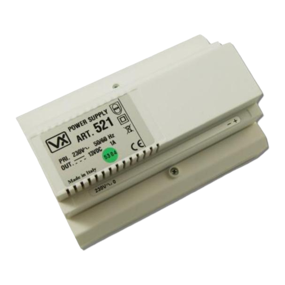
Page 14: Art.521 Power Supply
: 230Vac @ 50/60Hz +/- 10% Output Voltage : 13.5Vdc +/- 10% Current (continuous) : 800mA, (surge 1A max.) Module Dimensions : 157.5mm (L) x 105mm (W) x 65mm (D) Working Temp. : -10 +50 25H/SP/DDA/2W - TECHNICAL MANUAL EN-UK - V.1.2 - 04/01/16... -
Page 15: Software Installation And Setup
Launch the 2X00PC software by double clicking on the desktop icon. the top of the window the software will show that it is checking for any devices connected to the PC or laptop. 25H/SP/DDA/2W - TECHNICAL MANUAL EN-UK - V.1.2 - 04/01/16... -
Page 16: The Main Programmer Screen
I1, I2, I3, I4 or I5 has been triggered). • Aux. Out Time - the auxiliary output time can be set (in seconds, from 1 to 99 seconds) in this field. 25H/SP/DDA/2W - TECHNICAL MANUAL EN-UK - V.1.2 - 04/01/16... - Page 17 ‘name’ field under the ‘apartments’ tab (refer to page 19). 4. Call ID.27 - when set into mode 4 the UIM-138 will trigger the 138N speaker amp to call phone ID.27. 25H/SP/DDA/2W - TECHNICAL MANUAL EN-UK - V.1.2 - 04/01/16...
- Page 18 3 the auxiliary output AO will activate for the time period setup in the ‘Aux. Out Time’ field (described on page 16). The AO will activate from when the call button on the panel is pressed until the ‘Aux. Out Time’ expires. 25H/SP/DDA/2W - TECHNICAL MANUAL EN-UK - V.1.2 - 04/01/16...
- Page 19 From the top menu on the main programmer screen when ‘File’ is selected the following drop down menu will appear (as shown on page 20) and the following options are available: 25H/SP/DDA/2W - TECHNICAL MANUAL EN-UK - V.1.2 - 04/01/16...
- Page 20 (a specified file path and location can be selected as shown below). • Print - select this option from the drop down menu to print out the settings and the database file (as shown on page 21). 25H/SP/DDA/2W - TECHNICAL MANUAL EN-UK - V.1.2 - 04/01/16...
- Page 21 ‘Download’ is selected the following drop down menu will appear (as shown). Clicking on ‘Download All’ will download all the programming from the existing UIM-138 display module that the programmer software is connected to. 25H/SP/DDA/2W - TECHNICAL MANUAL EN-UK - V.1.2 - 04/01/16...
- Page 22 Art.2206N bus exchange device has been used. In most cases the ‘Upload All’ option described above would be used). The block ID in this field relates to the block ID number in the block ID column in the apartments ‘tab’ . 25H/SP/DDA/2W - TECHNICAL MANUAL EN-UK - V.1.2 - 04/01/16...
- Page 23 Language From the top menu on the main programmer screen when ‘Language’ is selected the following drop down menu will appear, as shown (the default language is English). 25H/SP/DDA/2W - TECHNICAL MANUAL EN-UK - V.1.2 - 04/01/16...
-
Page 24: The Status And Progress Bar
The ‘Refresh List’ option can be selected from the ‘Communication’ drop down list (from the top menu) and the status bar will confirm that the ports list has been updated, this can be seen to the right of the progress bar as shown below. 25H/SP/DDA/2W - TECHNICAL MANUAL EN-UK - V.1.2 - 04/01/16... - Page 25 UIM-138 display module. This is done by selecting ‘Upload All’ from the ‘Upload’ drop down list from the top menu. The status and upload progress can be seen to the right of the progress bar as shown below. 25H/SP/DDA/2W - TECHNICAL MANUAL EN-UK - V.1.2 - 04/01/16...
-
Page 26: Cable Requirements
(1 way “2 wire” DDA audio intercom kit) CABLE REQUIREMENTS The 25H/SP/DDA/2W audio kit follows the same cable requirements for the VX2200 (audio) system. The following tables below show the minimum number of cable cores required for this audio kit. -
Page 27: Block Cable Diagram
(1 way “2 wire” DDA audio intercom kit) BLOCK CABLE DIAGRAM Fig.2 below shows the minimum number of cable cores required for a 1 entrance 25H/SP/DDA/2W audio kit using the information taken from the tables shown on page 26. Art.3171... -
Page 28: Wiring Diagram
0V A0 I1 I2 I3 I4 I5 230Vac 50/60Hz Mains Input EMERGENCY DOOR RELEASE BREAK GLASS 1 2 3 4 5 6 7 8 PRESS HERE 1N4002 DIODE 12Vdc Fail Safe = pre-wired Lock Release 25H/SP/DDA/2W - TECHNICAL MANUAL EN-UK - V.1.2 - 04/01/16... -
Page 29: Lock Release Wiring And Back Emf Protection
IMPORTANT: PLEASE READ THESE INSTRUCTIONS CAREFULLY BEFORE COMMENCING WITH THE INSTALLATION. Videx recommends that any cabling and Videx product be installed by a competent and qualified electrician, security installation speclialist or communications engineer. DO NOT install any Videx product in areas where the following may be present or occur: •... -
Page 30: Power Supply Installation
(mains) cables. • Replace the terminal covers and fix them back into place using the relevant screws. • When all connections are made restore the mains supply. Fig.4B Fig.4C 25H/SP/DDA/2W - TECHNICAL MANUAL EN-UK - V.1.2 - 04/01/16... -
Page 31: Panel And Back Box Installation
Earthing the VR Panel and Back Box The VR intercom door panel must be earthed to its back box (with the earth strap provided) and then the back box earthed to the buildings earth connection. 25H/SP/DDA/2W - TECHNICAL MANUAL EN-UK - V.1.2 - 04/01/16... - Page 32 VIDEX 25H/SP/DDA/2W (1 way “2 wire” DDA audio intercom kit) Flush (VRFB120x280) Fig.5 Bezel (VRBB120x280) Fig.6 Surface (VRSB120x280) Fig.7 25H/SP/DDA/2W - TECHNICAL MANUAL EN-UK - V.1.2 - 04/01/16...
- Page 33 After the back box has been fitted the VR panel can then be fixed into position using the hex pin security screws provided and using a ‘torx’ screwdriver, as shown in Fig.9. Fig.9 25H/SP/DDA/2W - TECHNICAL MANUAL EN-UK - V.1.2 - 04/01/16...
-
Page 34: Panel Care And Maintenance
‘PRESS BUTTON TO CALL’ , as shown in Fig.11 PRESS BUTTON and will be ready to connect to a PC or laptop for programming (refer to pages 15 - 25 for software TO CALL installation and setup). Fig.11 25H/SP/DDA/2W - TECHNICAL MANUAL EN-UK - V.1.2 - 04/01/16... -
Page 35: Resetting The Art.uim-138 Display Module
5. Connect the USB cable between the PC and the UIM-138 display module. 6. Once the Programmer software setup is complete ‘double click’ on the programmer desktop icon to launch the software. 25H/SP/DDA/2W - TECHNICAL MANUAL EN-UK - V.1.2 - 04/01/16... -
Page 36: Trouble Shooting
Check the GND and +12Vdc connections on the Art.521 PSU and on panel the the intercom door panel Art.138N speaker, also check the voltage output on the PSU with and without does not switch ON. load. 25H/SP/DDA/2W - TECHNICAL MANUAL EN-UK - V.1.2 - 04/01/16... - Page 37 Check for voltage on the terminals of the lock (for fail secure locks 12Vdc should appear across the lock terminals, for fail safe locks 12Vdc should drop off the lock terminals). 25H/SP/DDA/2W - TECHNICAL MANUAL EN-UK - V.1.2 - 04/01/16...
-
Page 38: Notes
VIDEX 25H/SP/DDA/2W (1 way “2 wire” DDA audio intercom kit) NOTES 25H/SP/DDA/2W - TECHNICAL MANUAL EN-UK - V.1.2 - 04/01/16... - Page 39 VIDEX 25H/SP/DDA/2W (1 way “2 wire” DDA audio intercom kit) 25H/SP/DDA/2W - TECHNICAL MANUAL EN-UK - V.1.2 - 04/01/16...
- Page 40 VIDEX Southern Office Videx Security Ltd. 1 Osprey, Trinity Park Trinity Way’ London E4 8TD Northern Office Videx Security Ltd. Unit 4-7 Chillingham Industrial Estate Newcastle Upon Tyne NE6 2XX 25H/SP/DDA/2W - TECHNICAL MANUAL EN-UK - V.1.2 - 04/01/16...
Need help?
Do you have a question about the 25H/SP/DDA/2W and is the answer not in the manual?
Questions and answers