Advertisement
Quick Links
IP system - Accessories
Art. 2505
2 inputs - 2 outputs IP relay module
DESCRIPTION
2 inputs - 2 outpus IP relay module.
LEGEND
Mobile connection terminals
A
Relays status LEDs
B
L1 LED
C
P1 button for manual activation of relay 1
D
L2 LED
E
P2 button for manual activation of relay 2
F
PoE Ethernet interface with power LED
G
P3 button bootloader mode
H
RS485 termination jumper
I
Inputs status LEDs
L
L1 AND L2 LEDS - STATUS INDICATIONS
L1 and L2 LEDs (Fig. 1,
and
C
Slow flashing
The gateway is absent
Fast flashing
L1
Videx Cloud service is absent
OFF
All services are properly
connected
P1 AND P2 BUTTONS
MANUAL ACTIVATION OF RELAYS
P1 and P2 buttons (Fig. 1,
tivate a relay.
If the relay activates for a specific time it will remain actived for
the specified time.
If the relay operates in latch mode it will enable and disable
every time the button is pressed.
POE ETHERNET INTERFACE
The Ethernet connector (Fig. 1,
that the power supply is present, whether it is from PoE or via the connection terminals.
RS485 BUS TERMINATION SWITCH
The switch
sets the RS485 bus termination when connected to other RS485 devices.
I
By default the switch is set to the open position (lower position).
When more than one RS485 device is connected to the device in series on the RS485 bus
terminals then the switch can be set to the closed position (upper position) and only set
to the closed position on the end of line devices.
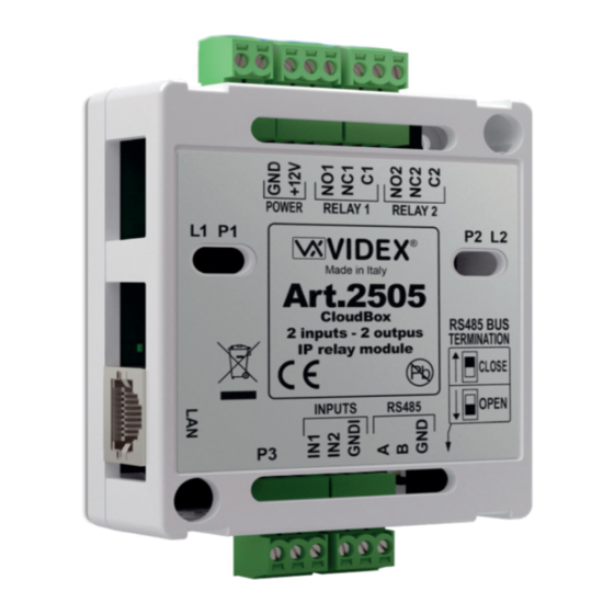
Art. 2505
- Installation instructions
C
D
G
H
Fig. 1 Front
) indicates the state of connections to the various services.
E
Slow flashing
The device is in "maintenace
mode" forced by Wizard
L2
software
OFF
The device is in normal working
mode
L1
Both fast flashing
and
The device is in "bootloader"
L2
mode
and
) are used for manually ac-
D
F
) is a standard RJ45 with PoE function. A red LED is placed close to the connector and indicates
G
POWER
RELAY 1
RELAY 2
L1
P1
Made in Italy
Art.2505
CloudBox
2 inputs - 2 outpus
IP relay module
INPUTS
RS485
P3
P3 BUTTON
BOOTLOADER MODE
P3 button (Fig. 1,
1. Remove the mains;
2. Press and keep pressed P3 button;
3. Restore the mains: L1 and L2 LED's are flashing fast to indicate
that the device is in "bootloader" mode.
- 1 -
A
B
P2
L2
E
F
RS485 BUS
TERMINATION
CLOSE
OPEN
I
L
A
Fig. 2 Left side
RELAYS AND INPUTS STATUS LEDS
These LEDs (Fig. 1,
B
when a relay or a input is energized.
) is used to start the "bootloader" mode:
H
RS485 open
Move the switch
position
RS485 closed
Move the switch
position
66251830 - V1.2 - 30/04/21
Rev.0.1
G
and
) indicate
L
to the lower
I
to the upper
I
Advertisement

Related Manuals for Videx 2505


Summary of Contents for Videx 2505
- Page 1 Slow flashing The gateway is absent The device is in “maintenace mode” forced by Wizard Fast flashing software Videx Cloud service is absent The device is in normal working All services are properly mode connected Both fast flashing The device is in “bootloader”...
-
Page 2: Technical Specification
Art. 2505 2 inputs- 2 outpus IP relay module PROGRAMMING All programming is carried out through the Videx IP Wizard software. To download the programming software On the lower side of the device there is a QR code with MAC ad- VX IP Wizard and obtain the latest firmware dress and the various parameters. - Page 3 Il gateway è assente Il dispositivo è in “modalità manutenzione” forzata dal Lampeggio veloce software Wizard Il servizio Videx Cloud è assente Il dispositivo è nella modalità di Tutti i servizi correttamente lavoro normale connessi Entrambi lampeggio veloce Il dispositivo è in modalità...
-
Page 4: Specifiche Tecniche
PROGRAMMAZIONE Tutte le programmazioni vengono effettuate tramite il software Per scaricare il software di programmazione Videx IP Wizard. VX IP Wizard ed ottenere gli ultimi aggiorna- Sul lato inferiore del dispositivi è presente un codice QR conte- meni di firmware e manuali è necessario regi- nente l’indirizzo MAC e altri parametri... - Page 5 Relay 1 Relay 2 2505 2505 2505 2505 IPure-diagram-002-EN V1.0 - 15/04/21 Active low input 1 Active low input 2 Videx Electronics S.p.A. www.videx.it Electric Push button 1 Push button 2 lock Electric lock Gate Gate - 5 - 66251830 - V1.2 - 30/04/21...
- Page 6 Art.2505 CloudBox mode Art.2505 modalità CloudBox 2505 2505 Smartphone with CloudNected app 6296 2505 2505 Smartphone with CloudNected app 6398 2505 2505 Smartphone with CloudNected app 6798 switch/router World Wide Electric lock HDR-15-12 Gate 4533X-2 plus 4045 - 6 -...
- Page 7 DISPOSAL In accordance with the Legislative Decree no. 49 of 14 March 2014 “Implementation of the Directive 2012/19/EU on waste electrical and electronic equipment (WEEE)”. The crossed-out bin symbol on the equipment or on the packaging indicates that when the product reaches the end of its lifetime, it must be collected separately from mixed municipal waste.
- Page 8 MANUFACTURER VIDEX ELECTRONICS S.P.A. FABBRICANTE Via del Lavoro, 1 FABRICANT 63846 Monte Giberto (FM) Italy FABRICANTE Tel (+39) 0734 631669 FABRIKANT Fax (+39) 0734 632475 www.videx.it - info@videx.it FABRICANTE ال� ش كة المص ن ِّ عة CUSTOMER SUPPORT VIDEX ELECTRONICS S.P.A.
Need help?
Do you have a question about the 2505 and is the answer not in the manual?
Questions and answers