Panasonic AK-UB300G Operating Instructions Manual
Multi-purpose camera
Hide thumbs
Also See for AK-UB300G:
- Operating instructions manual (52 pages) ,
- Operating instructions manual (48 pages)
Table of Contents
Advertisement
Quick Links
Advertisement
Table of Contents

Related Manuals for Panasonic AK-UB300G


Summary of Contents for Panasonic AK-UB300G
-
Page 1: Operating Instructions
Operating Instructions Multi-Purpose Camera AK-UB300G Model No. Before operating this product, please read the instructions carefully and save this manual for future use. Before using this product, be sure to read “Read this first!” (pages 3 to 6). ENGLISH W1116HM0 -YI... - Page 2 f Microsoft , Windows , Windows 7, Windows 8, Windows 8.1, Windows 10, Internet Explorer , ActiveX , and DirectX are registered trademarks or ® ® ® ® ® ® ® ® ® trademarks of Microsoft Corporation in the United States, Japan, and/or other countries. f Apple, Mac, and OS X are trademarks of Apple Inc., registered in the United States and other countries.
-
Page 3: Read This First
Read this first! Read this first! indicates safety information. WARNING: CAUTION: • To reduce the risk of fire or electric shock, do not Do not leave the unit in direct contact with the skin expose this equipment to rain or moisture. for long periods of time when in use. -
Page 4: Fcc Warning
Read this first! indicates safety information. FCC NOTICE (USA) This device complies with Part 15 of the FCC Rules. Operation is subject to the following two conditions: (1) This device may not cause harmful interference, and (2) this device must accept any interference received, including interference that may cause undesired operation. -
Page 5: Important Safety Instructions
Read this first! IMPORTANT SAFETY INSTRUCTIONS 1) Read these instructions. 2) Keep these instructions. 3) Heed all warnings. 4) Follow all instructions. 5) Do not use this apparatus near water. 6) Clean only with dry cloth. 7) Do not block any ventilation openings. Install in accordance with the manufacturer’s instructions. 8) Do not install near any heat sources such as radiators, heat registers, stoves, or other apparatus (including amplifiers) that produce heat. - Page 6 мільйон; 6. полібромдефенілові ефіри (PBDE) – не перевищує 0,1 % ваги речовини або в концентрації до 1000 частин на мільйон. Manufactured by: Panasonic Corporation, Osaka, Japan Importer’s name and address of pursuant to EU rules: Panasonic Marketing Europe GmbH Panasonic Testing Centre Winsbergring 15, 22525 Hamburg, Germany –...
-
Page 7: Table Of Contents
Contents Contents Read this first! [INTELLIGENT] [NETWORK SETUP] Chapter 1 Overview [FILE] [MAINTENANCE] Before using the camera [DIAGNOSTIC] Notes Chapter 5 Connecting to External Devices Required environment for computer Disclaimer Connecting the remote camera controller (AW-RP50N/ Notes regarding network AW-RP50E/AW-RP120G) Using the camera in a system Serial connection with the <I/F>... -
Page 8: Chapter 1 Overview
Overview Chapter 1 Before using the camera, read this chapter. -
Page 9: Before Using The Camera
This product includes MIT Licensed software. This product includes BSD Licensed software. For details on obtaining the source codes, visit the following website. http://pro-av.panasonic.net/ However, do not contact Panasonic for questions regarding obtained source codes. – 9 –... -
Page 10: Notes
OS X 10.8 Safari 6.1.2 Disclaimer In any case, Panasonic will not liable for any of the following: f Incidental, special, or consequential damage or harm caused directly or indirectly in regard to the camera f Trouble or malfunctions caused by the misuse or careless use of a user... -
Page 11: Using The Camera In A System
Chapter 1 Overview — Using the camera in a system Using the camera in a system An example of a standard system configured with the Multi-Purpose Camera (AK-UB300G) and peripheral devices is as follows. For details on the connected devices, refer to the Operating Instructions of each device. - Page 12 Chapter 1 Overview — Using the camera in a system f Remote camera controller Connect AW-RP50N/AW-RP50E or AW-RP120G to the <I/F> terminal or the <LAN> terminal. – 12 –...
-
Page 13: Accessories
Chapter 1 Overview — Accessories Accessories Mount cap (already attached to the product) Flange nut (x1) Wire mounting screws (x 2) NOTE t Properly dispose of the packaging materials after unboxing the product. – 13 –... -
Page 14: Frame Frequency Setting
Chapter 1 Overview — Frame frequency setting Frame frequency setting When the camera is shipped, the frame frequency is not set. Before using the camera for the first time, follow the steps below to set the frame frequency. SELECT FORMAT TYPE PLEASE SELECT FORMAT TYPE SET FORMAT TYPE 59.94Hz? FROM THE ITEM BELOW... -
Page 15: Chapter 2 Description Of Parts
Description of Parts Chapter 2 This chapter describes the names of the parts, functions, and operations of this camera. -
Page 16: Front Side
Chapter 2 Description of Parts — Front side Front side 1 Front tally lamp Lights up when the tally signal is supplied. Blinks in red while displaying warning, and blinks in green during the firmware update. NOTE t The brightness can be set with [MAIN MENU] → [SWITCH MODE] → [TALLY] → [FRONT TALLY]. Blinks in green [LOW] regardless of setting during the firmware update. -
Page 17: Left Side
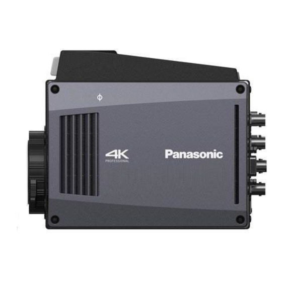
Chapter 2 Description of Parts — Left side Left side 1 < > mark Indicates the imaging plane inside the camera. – 17 –... -
Page 18: Right Side
Chapter 2 Description of Parts — Right side Right side 1 < > mark Indicates the imaging plane inside the camera. – 18 –... -
Page 19: Rear Side
Chapter 2 Description of Parts — Rear side Rear side 1 Back tally lamp Lights up when the tally signal is supplied. Blinks in red while displaying warning, and blinks in green during the firmware update. NOTE t The brightness can be set with [MAIN MENU] → [SWITCH MODE] → [TALLY] → [BACK TALLY]. Blinks in green [LOW] regardless of setting during the firmware update. -
Page 20: Upper Side
Chapter 2 Description of Parts — Upper side Upper side 1 Drop prevention wire mounting screw hole f Mounting hole size - M4 2 Mounting screw holes This is used when installing in a camera housing, etc. f Mounting hole size - 1/4-20 UNC (x 3) NOTE t Depth of the screw hole is 10 mm. -
Page 21: Bottom Side
Chapter 2 Description of Parts — Bottom side Bottom side 1 Mounting screw holes This is used when installing in the camera housing, or attaching the pan head or the tripod. f Mounting hole size - 1/4-20 UNC (x 3) - 3/8-16 UNC (x 2) NOTE t Depth of the screw hole is 10 mm. -
Page 22: Chapter 3 Operation
Operation Chapter 3 This chapter describes the operation of this camera. -
Page 23: On-Screen Displays Of The Monitor
Chapter 3 Operation — On-screen displays of the monitor On-screen displays of the monitor The setting and the operation status of the Multi-Purpose Camera are displayed in the monitor screen. All items that can be displayed are located as follows. 2160-59.94P H.SENS. -
Page 24: On-Screen Displays Of The Monitor
Chapter 3 Operation — On-screen displays of the monitor 11 Color temperature display Indicates the color temperature that is set on the camera. This can be either the memory value when automatic white balance is performed or the value configured in the menu. 12 Shutter speed display Current shutter speed is displayed. -
Page 25: Data
Chapter 3 Operation — Data Data The following shows the data handled in the camera. Managed system Name Quantity Description component Camera User file 1 - 3 These files contain equipment configuration data held by the camera, set in [MAIN MENU]. The data is managed by the camera. -
Page 26: Operation Procedure
Chapter 3 Operation — Operation procedure Operation procedure Turn on the power of each device. Illuminate the subject appropriately. Adjust the lens flange back and adjust the iris and focus. Always perform the lens flange back adjustment when using the camera for the first time or when the lens is changed. Adjust the white balance. -
Page 27: Adjustment For Shooting
Chapter 3 Operation — Adjustment for shooting Adjustment for shooting Lens flange back adjustment The lens flange back is an adjustment to focus in all ranges from the most telephoto to the most wide-angle of the zoom lens. Adjustment is necessary when using a zoom lens. -
Page 28: Genlock Adjustment
Chapter 3 Operation — Adjustment for shooting Genlock adjustment The video signal output from the camera can be locked to the reference signal supplied from an external source. This camera can receive the external reference signal from the <G/L IN> terminal or the <I/F> terminal. Supply HD-Y signal or composite signal matching the frame frequency of the system to the <G/L IN>... -
Page 29: Image Quality Adjustment
Chapter 3 Operation — Image quality adjustment Image quality adjustment The image quality of the video to be recorded can be set in [MAIN MENU] → [PAINT]. Measurement equipment such as vector scope is necessary to set in a higher level. Detail function This function thickens or weakens the outlines of images. -
Page 30: Rb Gain Control Function
Chapter 3 Operation — Image quality adjustment RB gain control function This is a function to set to add or reduce intensity of red and blue. This operates with automatic white balance. This will not operate with auto tracking white balance. r General settings Use the camera with the factory settings. -
Page 31: Color Correction Function
Chapter 3 Operation — Image quality adjustment Color correction function This function sets color saturation and phase. It applies individual effect on 12 phases in an image. It can be set to individual color hue. Yl-R R-Mg PHASE G-Yl Mg-B Cy-G B-Cy r General settings... -
Page 32: Knee Function
Chapter 3 Operation — Image quality adjustment Knee function This function sets the compression of video signals to prevent halation in images. r General settings Use the camera with the factory settings. r Advanced settings Set in [MAIN MENU] → [PAINT] → [KNEE]. f When [AUTO] is selected in [MAIN MENU] →... -
Page 33: Intelligent Function
Chapter 3 Operation — Intelligent function Intelligent function The brightness and color temperature changes drastically in the morning → day time → dusk → night at the outdoor where the camera is used. The intelligent function will automatically correct the image level and color temperature in accordance with the change at outdoor. Outdoor will drastically change as follows. -
Page 34: Multi-Formats
Chapter 3 Operation — Multi-formats Multi-formats The video output method for UHD, HD crop (UHD CROP) from UHD and HD can be selected with [MAIN MENU] → [SYSTEM MODE] → [FORMAT]. f The output from the <HD SDI OUT 1> terminal and the <UHD/HD SDI OUT 1> to <UHD/HD SDI OUT 4> terminals are used as the main line. Characters such as menu or status cannot be superimposed. - Page 35 Chapter 3 Operation — Multi-formats [MAIN MENU] Output terminal <UHD/HD SDI OUT 1> <UHD/HD SDI OUT 2> <UHD/HD SDI OUT 3> <UHD/HD SDI OUT 4> [FORMAT] terminal terminal terminal terminal (Main line) (Main line) (Main line) (Main line) [1080/23.98PsF] 1080/23.98psf No output [1080/23.98p] 1080/23.98p over 59.94i...
-
Page 36: Convenient Shooting Functions
Chapter 3 Operation — Convenient shooting functions Convenient shooting functions Scan reverse shooting Image can be displayed reversed vertically or horizontally by setting [MAIN MENU] → [SYSTEM MODE] → [SCAN REVERSE]. Displaying the zebra pattern The camera can display two types of zebra patterns. The zebra pattern set by the menu is displayed by setting [MAIN MENU] →... -
Page 37: Color Bar
Chapter 3 Operation — Convenient shooting functions NOTE t This will only operate in the HD mode. This will not operate in the UHD mode/UHD CROP mode. Color bar The color bar convenient to adjust the image quality of a TV or an external monitor can be displayed. Three types of color bar type ([FULL]/[SMPTE]/[ARIB]) can be selected in [MAIN MENU] →... -
Page 38: Uhd Crop Function
Chapter 3 Operation — Convenient shooting functions Using the flash band compensation function The flash band compensation function is activated when there are large changes in brightness at the bottom of the screen regardless of whether there is flash strobe light. The flash band compensation function may be activated depending on the shooting environment such as where a bright window has zoomed in and then out. -
Page 39: Haze Elimination Function
Chapter 3 Operation — Convenient shooting functions If the crop frame is overlapping in the same position, the crop frame selected in [CROP OUT SEL] will be prioritized, and then it is displayed in the order of [YL], [G], and [MG]. To move the crop frame f Selects the color of the crop frame in [MAIN MENU] →... -
Page 40: Chapter 4 Menu Operations
Menu Operations Chapter 4 This chapter describes how to operate the camera menus and the structure and details of the setting menu. -
Page 41: Menu Operations
Chapter 4 Menu Operations — Menu operations Menu operations Basic operations <MENU> button MAIN MENU DISPLAY SETUP SWITCH MODE PAINT SYSTEM MODE IN/OUT SELECT INTELLIGENT NETWORK SETUP FILE MAINTENANCE DIAGNOSTIC Fig. 1 Jog dial button DISPLAY SETUP MARKER (1/3) MARKER FOCUS ASSIST SW MONITOR DISPLAY FOCUS ASSIST... -
Page 42: Menu Operations
Chapter 4 Menu Operations — Menu operations Entering characters SCENE FILE SCENE FILE MODE STORE MODE STORE FILE SEL SCENE FILE SEL SCENE FILE NO. FILE NO. FILE NAME :SCENE1 FILE NAME :SCENE1 EXECUTE EXECUTE Fig. 1 Fig. 2 SCENE FILE SCENE FILE MODE STORE... -
Page 43: Menu Configuration
Chapter 4 Menu Operations — Menu configuration Menu configuration [MAIN MENU] [DISPLAY SETUP] Configures the setting regarding what to be displayed in the monitor. [SWITCH MODE] Configures the function assigned to the switch. [PAINT] Configures the image settings. [SYSTEM MODE] Configures the system frequency and shooting mode. -
Page 44: Menu List
Chapter 4 Menu Operations — Menu list Menu list : Can be saved and loaded as a scene file data. : Can be saved and loaded as a user file data. [DISPLAY SETUP] [MARKER] Item Description of settings [FOCUS ASSIST SW] Enables/disables the focus assist switch. -
Page 45: [Switch Mode]
Chapter 4 Menu Operations — Menu list [MONITOR DISPLAY] Item Description of settings [F NUMBER] Shows/hides the iris display (F value). [OFF], [ON] f Factory setting: [OFF] This is displayed when you use a lens that outputs position information. [ZOOM] Shows/hides the zoom position display. -
Page 46: Menu Operations
Chapter 4 Menu Operations — Menu list [DIGITAL EXTENDER] Item Description of settings [DIGITAL EXTENDER] Enables/disables the function to double the image by digital process. [OFF], [ON] f Factory setting: [OFF] [GAIN SETTING] Item Description of settings [GAIN SELECT] Switches the gain switch. [LOW], [MID], [HIGH], [S.GAIN1], [S.GAIN2], [S.GAIN3] f Factory setting: [LOW] [LOW GAIN]... -
Page 47: Menu Operations
Chapter 4 Menu Operations — Menu list [IRIS] Item Description of settings [WINDOW SELECT] Sets the photometric range. [1] - [4] The image of window will be as follows. f Factory setting: [1] [IRIS LEVEL] Adjusts the target value (brightness) of the auto iris. [0] - [100] f Factory setting: [50] [PEAK RATIO]... -
Page 48: [Paint]
Chapter 4 Menu Operations — Menu list Item Description of settings [SHUTTER SPEED] Sets the shutter speed when [SHUTTER MODE] is [SHUTTER]. [59.94i]/[59.94p] mode: [1/100], [1/120], [1/125], [1/250], [1/500], [1/1000], [1/1500], [1/2000], [180.0deg], [172.8deg], [144.0deg], [120.0deg], [90.0deg], [45.0deg] [50i]/[50p] mode: [1/60], [1/100], [1/125], [1/250], [1/500], [1/1000], [1/1500], [1/2000], [180.0deg], [172.8deg], [144.0deg], [120.0deg], [90.0deg], [45.0deg] [29.97p] mode:... -
Page 49: Menu Operations
Chapter 4 Menu Operations — Menu list Item Description of settings [GAMMA] Enables/disables gamma. [OFF], [ON] f Factory setting: [ON] [BLACK GAMMA] Enables/disables black gamma. [OFF], [ON] f Factory setting: [OFF] [KNEE] Enables/disables knee. [OFF], [MANUAL], [AUTO] f Factory setting: [MANUAL] [WHITE CLIP] Enables/disables white clips. -
Page 50: Menu Operations
Chapter 4 Menu Operations — Menu list Item Description of settings [R GAIN] Sets the correction level of red to the color temperature. [−400] - [+400] f Factory setting: [0] [B GAIN] Sets the correction level of blue to the color temperature. [−400] - [+400] f Factory setting: [0] [G AXIS]... -
Page 51: Menu Operations
Chapter 4 Menu Operations — Menu list Item Description of settings [V SAW G] Adjusts the white shading gain for Gch vertically using a saw-toothed waveform. [−100] - [+100] f Factory setting: [0] [V SAW B] Adjusts the white shading gain for Bch vertically using a saw-toothed waveform. [−100] - [+100] f Factory setting: [0] [V PARA R]... -
Page 52: Menu Operations
Chapter 4 Menu Operations — Menu list Item Description of settings [MASTER BLACK GAMMA] Adjusts the gamma characteristic adjacent to black. [−32] - [+32] f Factory setting: [0] [R BLACK GAMMA] Adjusts the gamma characteristic of red adjacent to black to the master gamma. [−20] - [+20] f Factory setting: [0] [B BLACK GAMMA]... -
Page 53: Menu Operations
Chapter 4 Menu Operations — Menu list [DRS] Item Description of settings [DRS] Enables/disables the dynamic range stretcher function. Set this to [ON] to automatically adjust the contrast. [OFF], [ON] It is displayed as [---] in the UHD mode/UHD CROP mode. f Factory setting: [OFF] [EFFECT DEPTH] Sets the compression level of the high-luminance areas of the dynamic range stretcher function. -
Page 54: Menu Operations
Chapter 4 Menu Operations — Menu list [DOWNCON DETAIL SETTING] This item is not displayed in the HD mode. Item Description of settings [DETAIL] Enables/disables all detail functions. [OFF], [ON] f Factory setting: [ON] [MASTER DETAIL] Sets the master detail. [−31] - [+31] f Factory setting: [0] [H DETAIL LEVEL]... - Page 55 Chapter 4 Menu Operations — Menu list Item Description of settings [ZEBRA EFFECT Selects the table of the zebra display. MEMORY] [A], [B], [C], [A+B], [A+C], [B+C], [A+B+C] f Factory setting: [A+B+C] [SKIN TONE EFFECT MEMORY] Selects the skin tone table used to apply the skin tone detail. [A], [B], [C], [A+B], [A+C], [B+C], [A+B+C] f Factory setting: [A+B+C] [SKIN TONE CRISP]...
-
Page 56: Menu Operations
Chapter 4 Menu Operations — Menu list Item Description of settings [MATRIX (B-R)_N] Adjusts the linear matrix between blue and red. This item is not available when [MATRIX] is set to [OFF]. [−31] - [+31] f Factory setting: [0] [MATRIX (B-R)_P] Adjusts the linear matrix between blue and red. -
Page 57: Menu Operations
Chapter 4 Menu Operations — Menu list Item Description of settings [CY-G PHASE] Adjusts the hue between green and cyan. [−127] - [+127] f Factory setting: [0] [CY PHASE] Adjusts cyan hue. [−127] - [+127] f Factory setting: [0] [B-CY PHASE] Adjusts the hue between cyan and blue. -
Page 58: [System Mode]
Chapter 4 Menu Operations — Menu list [SCENE FILE] Item Description of settings [MODE] Selects the operation mode. [LOAD], [STORE] f Factory setting: [LOAD] [FILE NO.] Selects a file number. When [MODE] is [LOAD]: [OFF], [1] - [8] When [MODE] is [STORE]: [1] - [8] f Factory setting: [OFF] [FILE NAME] Enters a file name. -
Page 59: [Intelligent]
Chapter 4 Menu Operations — Menu list Item Description of settings [DISPLAY STATUS/BAR [CAM ID SWITCH] Sets the status display to superimpose in the main line signal. OSD] [OFF]: Camera ID is not displayed. [BAR]: Camera ID is displayed only when set to [BAR]. [ON]: Camera ID is constantly displayed. -
Page 60: [Network Setup]
Chapter 4 Menu Operations — Menu list Item Description of settings [IRIS LIMIT] Sets the iris control range for the auto gain control operation. [1]: F2.0 - F8 [2]: F2.0 - F11 [3]: F2.0 - F16 f Factory setting: [2] [ATW SPEED] Sets the convergence time for the auto tracking white balance in 5 steps. -
Page 61: [Maintenance]
Chapter 4 Menu Operations — Menu list Item Description of settings [FILE NAME] Enters a file name. (15 characters or less) f Factory setting: [SCENE1] [EXECUTE] Selects whether to execute with the configured settings. [NO], [YES] [USER FILE] Item Description of settings [MODE] Selects the operation mode. -
Page 62: [Diagnostic]
Chapter 4 Menu Operations — Menu list Item Description of settings [W V SAW R] Adjusts Rch white shading for the data selected in [FILE NO.] vertically using a saw-toothed waveform. [−100] - [+100] f Factory setting: [0] [W V SAW G] Adjusts Gch white shading for the data selected in [FILE NO.] vertically using a saw-toothed waveform. - Page 63 Chapter 4 Menu Operations — Menu list [HOUR METER] Item Description of settings [FAN] Display the operating time of the fan. [0000000] - [1193046] [OPERATION] Display the operating time of the camera head. [0000000] - [1193046] – 63 –...
-
Page 64: Chapter 5 Connecting To External Devices
Connecting to External Devices Chapter 5 This chapter describes the external devices that can be connected to the camera. -
Page 65: Connecting The Remote Camera Controller (Aw-Rp50N/Aw-Rp50E/Aw-Rp120G)
Chapter 5 Connecting to External Devices — Connecting the remote camera controller (AW-RP50N/AW-RP50E/AW-RP120G) Connecting the remote camera controller (AW-RP50N/AW-RP50E/AW-RP120G) f Some of the functions can be controlled remotely by connecting the remote camera controller AW-RP50N/AW-RP50E/AW-RP120G (optional). f The unit can be controlled without using the pan head by the direct connection control of the remote camera controller AW-RP50N/AW-RP50E/ AW-RP120G. - Page 66 Chapter 5 Connecting to External Devices — Connecting the remote camera controller (AW-RP50N/AW-RP50E/AW-RP120G) Controlling the UHD cropping function r Controlling by AW-RP50N/AW-RP50E Press the <MENU> button to illuminate the button. Press the <9 SETUP> button in <PRESET MEMORY/MENU> to illuminate the button. Turn the <F1>...
-
Page 67: Ip Connection With The
Chapter 5 Connecting to External Devices — Connecting the remote camera controller (AW-RP50N/AW-RP50E/AW-RP120G) IP connection with the <LAN> terminal (Example 1) When connecting without going through a hub POWER ALARM CAMERA MENU PAGE GAIN/PED R/B GAIN R/B PED AWB/ABB SHUTTER EXIT STORE DELETE...Terminal -
Page 68: Chapter 6 Web Screen
Web Screen Chapter 6 This chapter describes how to configure the settings from a computer. -
Page 69: Setting The Network
Setting the network Software Download EASY IP Setup Software (EasyIPSetup.exe) from the following website, and install it. (Windows) http://pro-av.panasonic.net/ r EASY IP Setup Software (EasyIPSetup.exe) This software is used for configuring the network settings of the camera. (page 69) r Plugin software for the display Install the plugin software (Network Camera View 4S) required to display the IP images of the camera on a web browser. -
Page 70: Installing The Plugin Software For Display
Chapter 6 Web Screen — Setting the network f After clicking the [Save] button, it will take approximately two minutes to complete configuration of the camera. Disconnecting the AC adaptor or LAN cable before the configuration has been completed will invalidate the settings. In such a case, configure the settings again. -
Page 71: Displaying The Web Screen
Chapter 6 Web Screen — Displaying the web screen Displaying the web screen You can connect the camera to a computer to view IP images of the camera on a web browser or to configure various settings. To connect the camera’s IP control LAN terminal and a computer directly, use a crossover LAN cable. To connect via a switching hub, etc., use a straight-through LAN cable. -
Page 72: Switching [Live]/[Setup] Screens
Chapter 6 Web Screen — Displaying the web screen It is also recommended that the password is changed regularly. t If you attempt to display multiple H.264 videos on a single computer, the IP images may not be displayed depending on the specifications of the computer. -
Page 73: [Live] Screen (Single Display Mode)
Chapter 6 Web Screen — [Live] screen (single display mode) [Live] screen (single display mode) The camera image can be displayed on the computer. The items displayed differ between when [H.264] is selected and when [JPEG] is selected with the [Compression] button. r H.264 r JPEG 1 Main area (IP image display area) (page 74) -
Page 74: Names And Functions Of Parts ([Live] Screen)
Chapter 6 Web Screen — [Live] screen (single display mode) Names and functions of parts ([Live] screen) Main area (IP image display area) This area displays the IP images of the connected camera. You can use the digital zoom of the plugin software for display by operating the mouse wheel in the area. (Windows) f Depending on the computer being used, the drawing processor (GDI) of the OS may have restrictions and the images may cause tearing (part of images show deviated display) at major changes of shooting scenes. - Page 75 Chapter 6 Web Screen — [Live] screen (single display mode) 2 [JPEG] Displays JPEG images. In the following cases, the selection status of the [Compression] button returns to the setting in [Stream] for [Initial display settings for "Live" page] in the [Video over IP] tab.
- Page 76 Chapter 6 Web Screen — [Live] screen (single display mode) 1 [1920×1080] The image in the main area is displayed in the resolution of 1920 × 1080. 2 [1280×720] The image in the main area is displayed in the resolution of 1280 × 720. 3 [640×360] The image in the main area is displayed in the resolution of 640 ×...
-
Page 77: [Live] Screen (Multi Display Mode)
Chapter 6 Web Screen — [Live] screen (multi display mode) [Live] screen (multi display mode) Confirms images from multiple cameras in a single screen (multi-screen). Up to four or 16 camera images can be confirmed at once. [Live] screen of corresponding camera in single display mode is displayed in a separate window by clicking the camera title in each image. To use the multi-screen, it is necessary to set the camera to display in multi-screen in advance. -
Page 78: [Setup] Screen
Chapter 6 Web Screen — [Setup] screen [Setup] screen Various settings of this camera can be configured. The setup menu is only available to users set as [1. Administrator] in [Access level]. (page 85) Logging in to the [Setup] screen Fig. -
Page 79: [Basic] Screen
Chapter 6 Web Screen — [Setup] screen 7 [Maintenance] button Clicking this button displays the [Maintenance] screen in the main area. (page 87) [Basic] screen Item Description of settings [Camera title] Enter the name of the camera. Clicking the [Set] button displays the entered name on the camera title display area. The factory setting value is the product number of the camera. - Page 80 Chapter 6 Web Screen — [Setup] screen Item Description of settings [Stream] Selects the image to be displayed on the [Live] screen. [H.264(1)]: Displays movie (H.264 (1)). [H.264(2)]: Displays movie (H.264 (2)). [H.264(3)]: Displays movie (H.264 (3)). [H.264(4)]: Displays movie (H.264 (4)). [JPEG(1)]: Displays still image (JPEG (1)).
- Page 81 Chapter 6 Web Screen — [Setup] screen r H.264 Set [Max bit rate (per client)], [Image capture size], [Image quality], etc. for H.264 image. (Windows) The following screen shows an example of [H.264(1)]. Item Description of settings [H.264 transmission] Sets whether to transmit H.264 images. [On]: Transmits H.264 images.
- Page 82 Chapter 6 Web Screen — [Setup] screen Item Description of settings [Control time period] Sets the duration for which the H.264 bitrate is controlled. Images are transmitted so that the average transmission amount in the selected duration will be the bitrate set in [Max bit rate (per client)].
-
Page 83: [Multi-Screen Setup] Screen
Chapter 6 Web Screen — [Setup] screen Item Description of settings [Unicast port1 (Image)] Sets the unicast port number (to be used when images are transmitted from the camera). This item must be configured when [Transmission type] is set to [Unicast port (MANUAL)]. [1024] - [50000] Only even numbers can be configured. -
Page 84: [User Mng.] Screen
Chapter 6 Web Screen — [Setup] screen Item Description of settings [IP address] Enter the IP address of the camera to display in the multi-screen. Maximum of four groups with four cameras in each group (16 cameras) can be registered. Enter as follows when the HTTP port number of the camera to display is changed. -
Page 85: [Network] Screen
Chapter 6 Web Screen — [Setup] screen Item Description of settings [Password] Enter a password. [Retype password] Number of characters that can be entered: 4 to 32 Characters that cannot be entered: Double-byte and single-byte symbols " & [Access level] Sets the access level for users. - Page 86 Chapter 6 Web Screen — [Setup] screen Item Description of settings [IP address(IPv4)] Enter the IP address of the camera. Enter an IP address that does not conflict with the ones set for computers or other network cameras. f Factory setting: [192.168.0.40] [Subnet mask] Enter the subnet mask of the camera.
-
Page 87: [Maintenance] Screen
Chapter 6 Web Screen — [Setup] screen Item Description of settings [Recommended network setting for internet] Sets the recommended configuration for making the camera public on the Internet. When the [Set] button is clicked, a dialog box appears indicating the setting configuration of the item is to be changed. - Page 88 - CAM FPGA: Approx. one minute - NETWORK and AVIO FPGA: Approx. two minutes - Others: 30 seconds or less t Use the following files specified by Panasonic as the software for update. - CPU Software - CAM MAIN RX_SOFT.srx - CPU Software –...
- Page 89 Chapter 6 Web Screen — [Setup] screen r Saving the network-related settings of the camera to a computer ([Download]) Perform the following procedure to save the network-related settings of the camera to a computer. Do not turn off the power of the camera while the download operation is in process. Do not perform any operation from the start of the download operation until its end.
-
Page 90: Chapter 7 Ub300 Setting Tool
UB300 Setting Tool Chapter 7 This chapter describes the changing of setting menu and updating the firmware using the UB300 Setting Tool. -
Page 91: Introduction
Camera information f IP address: Specify the IP address of AK-UB300G to connect. f Port number: Specify the port number of AK-UB300G to connect. The default for camera side is 80. r Authentication information f User name: Specify the account name with administrator privilege to be used at the time of connection. -
Page 92: Setup
Double-click the downloaded file. The file is expanded and setup.exe is displayed. The UB300 Setting Tool can be downloaded from the following site: http://pro-av.panasonic.net/ Double-click setup.exe. The introduction screen is displayed. From hereafter, install following the instruction of the installer. -
Page 93: Connection
When hub is used LAN cable (straight cable: optional) Set the IP address of the personal computer with a separate address of AK-UB300G within the range of private address. Set the subnet mask to the same address as AK-UB300G. (Example) f Personal computer: 192.168.0.100... -
Page 94: Operation
Selects the setting menu to change in the connected AK-UB300G. 5 [OSD Menu Operation] button This is the button for the OSD operation. This can display the OSD menu or operate the cursor against the output image of AK-UB300G. 6 Menu setting screen Displays the setting menu for the category selected by the [Main Menu] button. -
Page 95: Connection Setting Screen
Sets the IP address of AK-UB300G to be connected. f [Port] Sets the port number of AK-UB300G to be connected. This setting is not necessary when the HTTP port number at the AK-UB300G side is not changed from its default. 2 [Authentication] f [User Name] Specifies the account name used to connect to AK-UB300G. -
Page 96: Setting Menu Screen
The items that can be changed from [Main Menu] of UB300 Setting Tool may change without prior notice. t The setting value of the displayed setting menu may not match with the connected AK-UB300G depending on the network environment or the status of the operating personal computer. -
Page 97: Chapter 8 Maintenance
Maintenance Chapter 8 This chapter describes the warning displays and after-sales services of the camera. -
Page 98: Troubleshooting
Chapter 8 Maintenance — Troubleshooting Troubleshooting For operations Problem Cause/solution The camera cannot be turned on. Does the power cable plugged into the power outlet securely? Operation from the IP connected remote camera Is the power turned on? controller is not possible f If the power lamp of the camera is not lit, the power of the camera is off. -
Page 99: For Ip Images
Chapter 8 Maintenance — Troubleshooting Problem Cause/solution The setting file cannot be downloaded. Is the file download function disabled? (Windows) Perform the following procedure to set. 1) Select [Tools] - [Internet Options] on Internet Explorer. 2) Click the [Security] tab, and then click the [Custom Level…] button on [Security level for this zone]. 3) On the [Security Setting] dialog box, set the [Enable] radio button of [Download file] to on. -
Page 100: Web Screen
Internet Explorer 1) Select [Grant(A)]. 9.0/10.0/11.0. [This webpage wants to run the following add- on: 'WebVideo Module' from 'Panasonic System Networks Co.,Ltd.'.] The information bar indicating the following Perform the following procedure to grant the permission. message appears on Internet Explorer 8.0. -
Page 101: Checking The Operating Time
Chapter 8 Maintenance — Checking the operating time Checking the operating time The operating time can be checked in [MAIN MENU] → [DIAGNOSTIC] → [HOUR METER]. [OPERATION]: Displays the total time of this unit powered up. [FAN]: Displays the run time of the fan. –... -
Page 102: Warning Displays
Chapter 8 Maintenance — Warning displays Warning displays Content of the warning is displayed in the output from the <HD SDI OUT 2> terminal when an error is detected while operating. Camera warning displays r When AWB (automatic white balance) is executed [AWB HIGH LIGHT NG] Automatic white balance cannot be executed because the light amount is excessive. -
Page 103: Updating The Camera Firmware
Chapter 8 Maintenance — Updating the camera firmware Updating the camera firmware Refer to the following website for new updates of the firmware and for operating instructions. http://pro-av.panasonic.net/ – 103 –... -
Page 104: Chapter 9 Specifications
Specifications Chapter 9 This chapter describes the specifications of this product. -
Page 105: Specifications
Chapter 9 Specifications — Specifications Specifications General Power DC e 12 V (DC 11 V–17 V) Power consumption 40 W (body only, when 3G SDI×4 is output) 60 W (maximum power when all accessories are connected and each output terminal is outputting at maximum) indicates safety information. -
Page 106: Video Input/Output
Chapter 9 Specifications — Specifications Video input/output <HD SDI OUT 1> terminal BNC × 1 3G/1.5G HD SDI: 0.8 V [p-p], 75 Ω <HD SDI OUT 2> terminal BNC × 1 3G/1.5G HD SDI: 0.8 V [p-p], 75 Ω <UHD/HD SDI OUT 1> terminal BNC×1 3G/1.5G HD SDI: 0.8 V [p-p], 75 Ω... -
Page 107: Details Of The Connector Signals
Chapter 9 Specifications — Details of the connector signals Details of the connector signals DC IN UNREG GND Not used Not used +12 V HA16RA-4P(77) (Hirose Electric Co.) NOTE t Use the external power supply with correct polarity. TALLY OUT R TALLY (open collector) G TALLY (open collector) UNREG+12 V (max. - Page 108 Chapter 9 Specifications — Details of the connector signals Not used Not used TX_N (EIA422)/TXD (EIA232) output RX_N (EIA422)/RXD (EIA232) input Not used G/L signal input Not used TX_P (EIA422) output RX_P (EIA422) input Not used D02-M15SAG-20L9E (Japan Aviation Electronics Industry) r Interface cable specifications Use a cable equivalent or higher performance than the following description.
-
Page 109: Index
Index Index Black balance adjustment Safety zone marker Black control function Scan reverse shooting [Setup] screen [Basic] screen Center marker [Image] screen Chroma setting function [Maintenance] screen Color bar [Multi-screen setup] screen Color correction function [Network] screen Connector signal [User mng.] screen Shutter mode Shutter speed Detail function... - Page 110 For more information about collection and recycling, please contact your local municipality, dealer or supplier. Penalties may be applicable for incorrect disposal of this waste, in accordance with national legislation. Web Site: http://www.panasonic.com © Panasonic Corporation 2016...
Need help?
Do you have a question about the AK-UB300G and is the answer not in the manual?
Questions and answers