Table of Contents
Advertisement
Before operating this product, please read the instructions carefully and save this manual for future use.
Before using this product, be sure to read "Read this first!" (pages 2 to 5).
GJ GSJ
W1020MZ0 -FJ
Operating Instructions
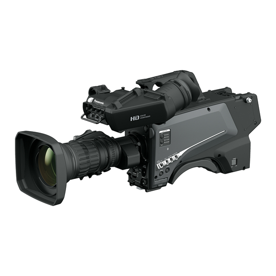
AK-HC3900G
Model No.
AK-HC3900GS
Model No.
HD Studio Camera
ENGLISH
DVQP2413ZA
Advertisement
Table of Contents

Related Manuals for Panasonic AK-HC3900G


Summary of Contents for Panasonic AK-HC3900G
- Page 1 Operating Instructions HD Studio Camera AK-HC3900G Model No. AK-HC3900GS Model No. Before operating this product, please read the instructions carefully and save this manual for future use. Before using this product, be sure to read “Read this first!” (pages 2 to 5).
- Page 2 Read this first! Read this first! indicates safety information. WARNING: CAUTION: This equipment must be earthed. Excessive sound pressure from earphones and headphones can cause hearing loss. To ensure safe operation, make sure that the optical cable is securely connected to an earthed CCU when in use. CAUTION: The fact that the equipment operates satisfactorily does Invisible Laser radiation is emitted from the Optical fiber...
- Page 3 FCC NOTICE (USA) Supplier’s Declaration of Conformity Model Number: AK-HC3900G/AK-HC3900GS Trade Name: Panasonic Responsible Party: Panasonic Corporation of North America Two Riverfront Plaza, Newark, NJ 07102 Support contact: 1-800-524-1448 This device complies with part 15 of the FCC Rules. Operation is subject to the following two conditions: (1) This device may not cause harmful interference, and (2) this device must accept any interference received, including interference that may cause undesired operation.
- Page 4 Read this first! IMPORTANT SAFETY INSTRUCTIONS 1) Read these instructions. 2) Keep these instructions. 3) Heed all warnings. 4) Follow all instructions. 5) Do not use this apparatus near water. 6) Clean only with dry cloth. 7) Do not block any ventilation openings. Install in accordance with the manufacturer’s instructions. 8) Do not install near any heat sources such as radiators, heat registers, stoves, or other apparatus (including amplifiers) that produce heat.
- Page 5 Read this first! AEEE Yönetmeliğine Uygundur. AEEE Complies with Directive of Turkey. Manufactured by: Panasonic Corporation, Osaka, Japan Importer’s name and address of pursuant to EU rules: Panasonic Marketing Europe GmbH Panasonic Testing Centre Winsbergring 15, 22525 Hamburg, Germany < Предупреждение >...
- Page 6 • • SDXC logo is a trademark of SD-3C, LLC. • • All other names, company names, product names, etc., contained in this instruction manual are trademarks or registered trademarks of their respective owners. • • Transferring, copying, disassembling, decompiling, reverse engineering, and exporting in violation of export laws of any software included with this product are strictly prohibited.
-
Page 7: Table Of Contents
Contents Contents Read this first! Chapter 7 Specifications Chapter 1 Overview Specifications Dimensions Before using the camera Specifications Notes Details of the connector signals Disclaimer Index Notes regarding network SD memory card Using the camera in a system Basic configuration devices Expanded configuration devices System block diagram Accessories... -
Page 8: Overview
Overview Chapter 1 Before using the camera, read this chapter. -
Page 9: Before Using The Camera
• • The cooling fan is a consumable supply. Replace it after approximately 50,000 hours of use. Be sure to contact your dealer for the replacement. „ Peripheral devices and software • • The software of the peripheral devices (CCU and ROP) that are connected to AK-HC3900G/AK-HC3900GS may require upgrading. • • For details, contact your dealer. - Page 10 Insert the SD card to which the file has been written into a computer and select "LICENSE.TXT". For details on these descriptions (originally provided in English) and how to obtain the source code, visit the following website. https://pro-av.panasonic.net/ We do not accept inquiries about the details of the source code obtained by the customer.
-
Page 11: Disclaimer
Notes Disclaimer In any case, Panasonic will not liable for any of the following: • • Incidental, special, or consequential damage or harm caused directly or indirectly in regard to the camera • • Trouble or malfunctions caused by the misuse or careless use of a user •... -
Page 12: Using The Camera In A System
Chapter 1 Overview — Using the camera in a system Using the camera in a system An example of a standard system consisting of the HD Studio Camera (AK-HC3900G/AK-HC3900GS) and peripheral devices is as follows. For details on the connected devices, refer to the Operating Instructions of each device. -
Page 13: System Block Diagram
Chapter 1 Overview — Using the camera in a system System block diagram (AK-HCU250P/ AK-HCU250PS/ AK-HCU250E/ AK-HCU250ES) (AK-HC3900G/AK-HC3900GS) a: Microphone kit b: 3.45-inch color viewfinder/1.5-inch HD viewfinder c: Handy lens d: Microphone holder e: 7-inch LCD color viewfinder f: Master setup unit... -
Page 14: Accessories
Chapter 1 Overview — Accessories Accessories Camera number sheet (1 to 12) Mount cap (already attached to the product) D-sub connector cover (already attached to the product) NOTE • • Properly dispose of the packaging materials after unboxing the product. –... -
Page 15: Working Frequency Setting
Chapter 1 Overview — Working frequency setting Working frequency setting When the camera is shipped, the working frequency is not set. Before using the camera for the first time, follow the steps below to set the working frequency. SELECT FORMAT TYPE SELECT FORMAT TYPE PLEASE SELECT FORMAT TYPE SET FORMAT TYPE 60Hz? -
Page 16: Chapter 2 Description Of Parts
Description of Parts Chapter 2 This chapter describes the names of the parts, functions, and operations of this camera. -
Page 17: Front Side
Chapter 2 Description of Parts — Front side Front side 1 Lens cable/microphone cable clamp Used for securing the lens and microphone cables. 2 Lens mount (Bayonet type) This is where the lens is mounted. 3 <SHUTTER> switch This is the electronic shutter switch. <OFF>: Disables the electronic shutter. -
Page 18: Left Side
Chapter 2 Description of Parts — Left side Left side 11 12 13 1 <LOCAL> lamp While this lamp is lit, the ND filter can be adjusted manually. 2 <FILTER LOCAL> switch This switch sets whether to adjust the ND filter manually or remotely. 3 ND filter selector switch <ND FILTER>... - Page 19 Chapter 2 Description of Parts — Left side 12 <WHITE BAL> switch Selects the white balance memory. Data can be recorded to <A> or <B>. <PRST>: The white balance configured in [MAIN MENU] → [PAINT] → [COLOR TEMP SETTING] is set. This switch cannot be used when the CCU or ROP is connected to the camera.
-
Page 20: Right Side
Chapter 2 Description of Parts — Right side Right side 1 <OPT FIBER> terminal Used to connect with the CCU using the optical fiber multi cable. When the terminal is not in use, attach the dust cap. 2 <LAN> terminal Used to connect the LAN cable (100BASE-TX/1000BASE-T). -
Page 21: Rear Side
Chapter 2 Description of Parts — Rear side Rear side 1 <CALL> lamp Lights up in green when the call switch is pressed from the ROP or CCU. 2 <CALL> switch While this switch is pressed, the call lamps on the ROP and CCU are lit and the ROP buzzer sounds. (When the ROP buzzer setting is enabled) NOTE •... - Page 22 Chapter 2 Description of Parts — Rear side 12 <LEVEL> dial (<INTERCOM>) Used to adjust the volume level of the intercom when the mixing function of the intercom connected to the <INTERCOM> terminal and the PGM is enabled. The mixing function of the intercom and the PGM can be enabled/disabled from [MAIN MENU] → [INTERCOM SETTING] → [INCOM RECEIVE SETTING] →...
-
Page 23: Upper Side
Chapter 2 Description of Parts — Upper side Upper side 1 Viewfinder front/back positioning lever To adjust the front/back position of the viewfinder, loosen this lever and slide the viewfinder forwards or backwards to adjust the viewfinder to a position that enables easy viewing. After adjusting the viewfinder, turn the lever towards <LOCK> to lock the position. 2 Viewfinder left-right positioning ring To adjust the left/right position of the viewfinder, loosen this lever and slide the viewfinder to the left or right to adjust the viewfinder to a position that enables easy viewing. -
Page 24: Chapter 3 Preparation
Preparation Chapter 3 Follow the procedures described in this chapter to mount the accessories before using the camera. -
Page 25: Attaching The Viewfinder
Chapter 3 Preparation — Attaching the viewfinder Attaching the viewfinder Attach the viewfinder (optional). Attaching the viewfinder HD viewfinder AJ-CVF50G (optional) can be used with this camera. For details on handling the HD viewfinder, refer to the Operating Instructions of the viewfinder. Viewfinder left-right positioning ring Knob Fig. -
Page 26: Attaching The Rear Viewfinder
Chapter 3 Preparation — Attaching the viewfinder Attaching the rear viewfinder LCD viewfinder AK-HVF100G (optional) can be used with this camera. For details on handling the LCD viewfinder, refer to the Operating Instructions of the viewfinder. Connector cover V-groove Lock release button V-shaped protrusion Fig. -
Page 27: On-Screen Displays Of The Viewfinder
Chapter 3 Preparation — On-screen displays of the viewfinder On-screen displays of the viewfinder HD Studio Camera settings and messages indicating operating statuses appear on the viewfinder screen. All items that can be displayed are located as follows. 59.94p HDR 1080/59.94p FAN OFF MENU RET1... - Page 28 Chapter 3 Preparation — On-screen displays of the viewfinder 8 Return ID display Displays the return ID of the current return output number. The ID (character string) set in [MAIN MENU] → [RETURN SETTING] → [RETURN1 ID] to [RETURN2 ID] is displayed. The following return IDs (character strings) are set in factory settings.
- Page 29 Chapter 3 Preparation — On-screen displays of the viewfinder 26 Focus information display Displays the focus information of the focus. NOTE • • This is displayed only when an auto focus lens with the function to return the focus information is mounted. 27 Optical level display Indicates the level of the optical signals the camera will receive.
-
Page 30: Connecting A Microphone
Chapter 3 Preparation — Connecting a microphone Connecting a microphone When mounting a microphone on the viewfinder (optional) for use A microphone such as microphone kit AJ-MC700P (optional) can be mounted on the viewfinder. Microphone holder Clamp screw Fig. 1 Fig. -
Page 31: When Mounting A Microphone Holder (Optional) For Use
Chapter 3 Preparation — Connecting a microphone When mounting a microphone holder (optional) for use Clamping screw Fig. 1 Fig. 2 Lock lever <MIC> terminal (front) Fig. 3 Fig. 4 Remove the screws on the microphone holder mounting position and mount the microphone holder AJ-MH800G (optional). (Fig. -
Page 32: Using External Dc Power Supply
Chapter 3 Preparation — Using external DC power supply Using external DC power supply DC cable External DC power supply <DC IN> terminal Connect the external DC power supply to the <DC IN> terminal on the camera. Turn on the <POWER> switch of the external DC power supply (if the external DC power supply has a <POWER> switch). Set the <POWER>... -
Page 33: Data
CAC file has a name specific to each lens and it can be downloaded from the website. You can check the CAC compatible lenses guaranteed for use with this camera on the Panasonic website. You can also obtain a CAC file from the support desk on the Panasonic website. -
Page 34: Chapter 4 Menu Operations
Menu Operations Chapter 4 This chapter describes how to operate the camera menus and the structure and details of the setting menu. -
Page 35: Menu Operations
Chapter 4 Menu Operations — Menu operations Menu operations Basic operations MAIN MENU (1/2) DISPLAY SETUP SWITCH MODE RETURN SETTING INTERCOM SETTING MIC SETTING PAINT HDR-PAINT SYSTEM MODE IN/OUT SELECT <MENU> button Fig. 1 <SELECT> dial button DISPLAY SETUP DSP SETUP > MARKER (1/4) MARKER FOCUS ASSIST SW VIEW FINDER DETAIL... - Page 36 Chapter 4 Menu Operations — Menu operations Entering characters FILE > SD CARD FILE > SD CARD MODE STORE MODE STORE FILE SEL SCENE FILE SEL SCENE FILE NO. FILE NO. FILE NAME :SCENE1 FILE NAME :SCENE1 SD FILE NO. SD FILE NO.
-
Page 37: Menu Configuration
Chapter 4 Menu Operations — Menu configuration Menu configuration [MAIN MENU] [DISPLAY SETUP] Configures the settings for the details to be displayed in the viewfinder. [SWITCH MODE] Configures the function assigned to the switch. [RETURN SETTING] Configures the return switch and return signal name. [INTERCOM SETTING] Configures the details such as gain, etc. -
Page 38: Menu List
Chapter 4 Menu Operations — Menu list Menu list : Can be saved and loaded as a scene file data. : Can be saved and loaded as a user file data. : Can be saved and loaded as an operation file data. : Can be saved and loaded as a reference file data. - Page 39 Chapter 4 Menu Operations — Menu list Item Description of settings [SAFETY MARK1 SWITCH] Shows/hides the safety marker 1. [OFF], [ON] • • Factory setting: [OFF] [SAFETY MARK1] Sets the aspect ratio of safety marker 1. [16:9], [15:9], [14:9], [13:9], [4:3] •...
- Page 40 Chapter 4 Menu Operations — Menu list [VIEW FINDER DETAIL] Item Description of settings [VIEW FINDER DETAIL] Adjusts the details of the viewfinder. [0]…[23] • • Factory setting: [7] [ZOOM LINK] Enables/disables the details of the zoom-interlocked viewfinder. [OFF], [ON] •...
- Page 41 Chapter 4 Menu Operations — Menu list Item Description of settings [RETURN SELECT] Shows/hides the return ID display. [OFF], [ON] • • Factory setting: [OFF] [STATUS] Shows/hides the display appearing when functions are selected. [OFF], [ON] • • Factory setting: [OFF] [STATUS(AUTO)] Shows/hides the display appearing when AWB/ABB/ASU are activated or deactivated.
-
Page 42: [Switch Mode]
Chapter 4 Menu Operations — Menu list [!LED] For items whose setting is [ON], the LED in the viewfinder ( ) lights up when the operating status of the camera becomes irregular. Item Description of settings [GAMMA OFF] Shows/hides the status display when gamma is disabled. [OFF], [ON] •... - Page 43 Chapter 4 Menu Operations — Menu list [GAIN SETTING] Item Description of settings [LOW GAIN] Sets the amount of gain increase when <L> is selected for the <GAIN> switch. [−6dB]…[36dB] • • Factory setting: [0dB] [OFFSET LOW GAIN] Sets the offset from [LOW GAIN]. [−2.9dB]…[+2.9dB] (0.1 dB step) •...
- Page 44 Chapter 4 Menu Operations — Menu list Item Description of settings [LENS EXT COMP LEVEL] Sets the iris compensation level when lens extender 3 is enabled. [−100]…[+100] • • Factory setting: [0] [EXTENDER4] Sets the magnification of lens extender 4. [NONE], [0.1]…[9.9] •...
- Page 45 Chapter 4 Menu Operations — Menu list Item Description of settings [SYNCHRO SCAN] Sets the shutter speed when [SHUTTER MODE] is [SYNCHRO]. [59.94i]/[59.94p] mode: [61.7Hz]…[6130Hz] • • Factory setting: [61.7Hz] [50i]/[50p] mode: [51.5Hz]…[6250Hz] [29.97p] mode: [30.9Hz]…[2600Hz] [25p] mode: [25.7Hz]…[3130Hz] [23.98p] mode: [24.7Hz]…[2880Hz] [SHUTTER SELECT] Item...
- Page 46 Chapter 4 Menu Operations — Menu list Item Description of settings [POSITION4] Sets the shutter speed of [POSITION4]. [59.94i]/[59.94p] mode: [1/100], [1/120], [1/125], [1/250], [1/500], [1/1000], [1/1500], [1/2000] • • Factory setting: [1/250] [50i]/[50p] mode: [1/60], [1/100], [1/125], [1/250], [1/500], [1/1000], [1/1500], [1/2000] •...
-
Page 47: [Return Setting]
Chapter 4 Menu Operations — Menu list Item Description of settings [POSITION8] Sets the shutter speed of [POSITION8]. [59.94i]/[59.94p] mode: [1/100], [1/120], [1/125], [1/250], [1/500], [1/1000], [1/1500], [1/2000] • • Factory setting: [1/2000] [50i]/[50p] mode: [1/60], [1/100], [1/125], [1/250], [1/500], [1/1000], [1/1500], [1/2000] •... -
Page 48: [Intercom Setting]
Chapter 4 Menu Operations — Menu list [INTERCOM SETTING] [INTERCOM] Item Description of settings [INCOM TALK SETTING] [MIC TYPE] Selects the type of the intercom microphone. [DYN]: Dynamic type [ECM]: Condenser type [CBN]: Carbon type • • Factory setting: [DYN] [MIC POWER] Sets the on/off for the power supply to the intercom microphone. - Page 49 Chapter 4 Menu Operations — Menu list Item Description of settings [WHITE CLIP] Enables/disables white clips. [OFF], [ON] • • Factory setting: [ON] [DRS SW] Enables/disables dynamic range stretcher. [OFF], [ON] In the UHD mode, [---] is displayed. • • Factory setting: [OFF] [DETAIL] Enables/disables the detail.
- Page 50 Chapter 4 Menu Operations — Menu list [COLOR TEMP SETTING] Item Description of settings [COLOR TEMP [COLOR TEMP PRE Enables/disables the color temperature adjustment. PRESET] SWITCH] [OFF], [ON] • • Factory setting: [OFF] [COLOR TEMP] Sets the color temperature when [COLOR TEMP PRE SWITCH] is [ON]. [2000K]…[15000K] •...
- Page 51 Chapter 4 Menu Operations — Menu list [RGB GAIN CONTROL SETTING] Item Description of settings [G GAIN REL CONTROL SWITCH] Enables/disables the relative value control of Gch gain. [OFF], [ON] • • Factory setting: [OFF] [RGB GAIN PRESET] [R GAIN] Sets the preset value of Rch gain.
- Page 52 Chapter 4 Menu Operations — Menu list Item Description of settings [V SAW B] Adjusts the white shading gain for Bch vertically using a saw-toothed waveform. [−100]…[+100] • • Factory setting: [0] [V PARA R] Adjusts the white shading gain for Rch vertically using a parabolic waveform. [−100]…[+100] •...
- Page 53 Chapter 4 Menu Operations — Menu list [KNEE] Item Description of settings [KNEE] — Enables/disables the knee function. This cannot be set in HDR mode. [OFF], [ON] • • Factory setting: [ON] [KNEE MASTER POINT] Sets the knee point position. [080.00%]…[110.00%] (0.25% step) •...
- Page 54 Chapter 4 Menu Operations — Menu list Item Description of settings [KNEE APERTURE LEVEL] Adjusts the knee aperture level. This cannot be set in HDR mode. [00]…[5] • • Factory setting: [0] [DETAIL KNEE] Adjusts the detail components of knee. This cannot be set in HDR mode.
- Page 55 Chapter 4 Menu Operations — Menu list Item Description of settings [SKIN GET] Selects whether to automatically obtain the color saturation and hue information from the cursor position. [NO], [YES] [MEMORY SELECT] Selects the skin tone table of the subject to apply the skin tone table to. [A], [B], [C] •...
- Page 56 Chapter 4 Menu Operations — Menu list Item Description of settings [I CENTER] Sets the center position on the I axis (the area where the skin tone effect is applied). [0]…[255] • • Factory setting: [140] (UHD mode), [33] (HD mode) [I WIDTH] Sets the width of the area where the skin tone effect is applied on the I axis with [I CENTER] being the center.
- Page 57 Chapter 4 Menu Operations — Menu list Item Description of settings [COLOR CORRECT Selects the table for color correction. TABLE] [A], [B] • • Factory setting: [A] [R SAT] Adjusts the color saturation of red. This item is not available when [COLOR CORRECT] is set to [OFF]. [−63]…[+63] •...
- Page 58 Chapter 4 Menu Operations — Menu list Item Description of settings [CY PHASE] Adjusts the hue of cyan. This item is not available when [COLOR CORRECT] is set to [OFF]. [−127]…[+127] • • Factory setting: [0] [CY_G PHASE] Adjusts the hue between cyan and green. This item is not available when [COLOR CORRECT] is set to [OFF].
-
Page 59: [Hdr-Paint]
Chapter 4 Menu Operations — Menu list [ROP CONTROL] Item Description of settings [CONTROL ROTATION MODE] Sets the control rotation mode of ROP. [MODE1], [MODE2] • • Factory setting: [MODE2] [HDR-PAINT] Configures the image settings during HDR. Item Description of settings [HLG MODE] Sets the mode of HLG. -
Page 60: [System Mode]
Chapter 4 Menu Operations — Menu list [SYSTEM MODE] [FORMAT] cannot be selected right after the power is turned on, because boot of the camera is in progress. This is not an error. Perform operation after a while. Item Description of settings [FORMAT] Sets the system format. -
Page 61: [Network Setup]
Chapter 4 Menu Operations — Menu list Item Description of settings [HD-SDI1 3G-SDI] Sets the output format when [HD-SDI1 OUT] is [CAM] and when the image output from the <HD SDI1> terminal is 3G output. [LEVEL-A], [LEVEL-B] • • Factory setting: [LEVEL-B] NOTE •... -
Page 62: [File]
Chapter 4 Menu Operations — Menu list [FILE] [SD CARD] [SD CARD] cannot be selected right after the power is turned on, because boot of the camera is in progress. This is not an error. Perform operation after a while. Item Description of settings [MODE]... -
Page 63: [Maintenance]
Chapter 4 Menu Operations — Menu list [CAC FILE] [CAC FILE] cannot be selected right after the power is turned on, because boot of the camera is in progress. This is not an error. Perform operation after a while. Item Description of settings [CARD FILE SELECT] Selects a file. - Page 64 Chapter 4 Menu Operations — Menu list Item Description of settings [FILE NO.] Selects a file. When [LENS FILE MODE] is [LOAD]: [1]…[32] When [LENS FILE MODE] is [STORE]: [1]…[32] • • Factory setting: [1] [FILE NAME] Enters a file name. (15 characters or less) •...
- Page 65 Chapter 4 Menu Operations — Menu list [F DROP ADJUST] Item Description of settings [F DROP RANGE] Sets the determination reference value for the F drop of the lens. [1]…[40] • • Factory setting: [10] [BLACK SHADING] Item Description of settings [CORRECT] Enables/disables the auto correction function of black shading.
-
Page 66: [Diagnostic]
Chapter 4 Menu Operations — Menu list [UPDATE] [UPDATE] cannot be selected right after the power is turned on, because boot of the camera is in progress. This is not an error. Perform operation after a while. Description of settings Updates the software. -
Page 67: Chapter 5 Network Settings
Network Settings Chapter 5 This chapter describes how to configure the settings from a computer. -
Page 68: Setting The User Account
Use the following procedure to register the account on this unit. Software To install the software, download User Account Setup Software (AccoutGen) from the following website. (Windows) https://pro-av.panasonic.net/ „ User Account Setup Software (AccoutGen) User account setting of this unit can be set using User Account Setup Software. -
Page 69: Chapter 6 Maintenance
Maintenance Chapter 6 This chapter describes the warning displays and after-sales services of the camera. -
Page 70: Troubleshooting
Chapter 6 Maintenance — Troubleshooting Troubleshooting For operations Problem Cause/solution The camera cannot be turned on. Does the power cable plugged into the power outlet securely? The camera cannot be operated from the ROP Is the power turned on? (AK-HRP1000G) that is connected via IP. •... -
Page 71: Checking The Operating Time
Chapter 6 Maintenance — Checking the operating time Checking the operating time The operating time can be checked in [MAIN MENU] → [DIAGNOSTIC] → [HOUR METER]. [HEAD]: The operating time of the camera head can be checked. – 71 –... -
Page 72: Warning Displays
Chapter 6 Maintenance — Warning displays Warning displays Warning displays appear when errors have occurred in camera’s auto functions. Camera warning displays „ When AWB (automatic white balance) is executed [AWB BREAK] Automatic white balance has been interrupted. [AWB HIGH LIGHT NG] Automatic white balance cannot be executed because the light amount is excessive. -
Page 73: Updating The Camera Firmware
Chapter 6 Maintenance — Updating the camera firmware Updating the camera firmware Refer to the following website for new updates of the firmware and for operating instructions. https://pro-av.panasonic.net/ – 73 –... - Page 74 Specifications Chapter 7 This chapter describes the specifications of this product.
- Page 75 Chapter 7 Specifications — Specifications Specifications Dimensions 151 mm (5-31/32 Inches) 369 mm (14-17/32 Inches) Specifications General Power 12 V (when using an external power supply) 190 V (when AK-HCU250P/AK-HCU250PS/AK-HCU250E/AK-HCU250ES is connected) Power consumption 82 W (maximum, when connecting to an external 12 V and including supply to an externally connected devices) 92 W (maximum, when AK-HCU250P/AK-HCU250PS/AK-HCU250E/AK-HCU250ES is conncected and including supply to an externally connected devices) indicates safety information.
- Page 76 Chapter 7 Specifications — Specifications Body only Dimensions (W×H×D) 151 mm × 267 mm × 369 mm (5-31/32 inches × 10-17/32 inches × 14-17/32 inches) (excluding protrusions) Camera unit Pickup device 11.14 million pixels, CMOS Sensor Optical filter ND: Clear, 1/4, 1/16, 1/64 Lens mount 2/3-type bayonet Sensitivity...
-
Page 77: Notes 11 Details Of The Connector Signals
Chapter 7 Specifications — Details of the connector signals Details of the connector signals OPT FIBER OPT-TX(Mark Band=IN) OPT-RX(Mark Band=OUT) AC240 V(C) AC240 V(H) STBY-SIG STBY-CONT TAJIMI ELECTRONICS OPT-TX(Mark Band=IN) OPT-RX(Mark Band=OUT) STBY-SIG STBY-CONT AC240 V(C) AC240 V(H) LEMO INTERCOM TALK GND TALK RECEIVE GND... - Page 78 Chapter 7 Specifications — Details of the connector signals LENS RET-SW IRIS-AUTO IRIS-CONT UNREG +12 V IRIS-POSI IRIS-G-MAX EXT-POSI ZOOM-POSI FOCUS POSI/LENS RXD IRIS AUTO/LENS TXD HR10A-10R-12SC (Hirose Electric Co.) VF (front) UNREG -12 V UNREG -12 V +9 V VF-P -OUT-GND VF-P...
- Page 79 Chapter 7 Specifications — Details of the connector signals VF (rear) VF-Y-OUT VF-P -OUT VF-P -OUT CAM DETECT I2C DATA R TALLY T TALLY UNREG +12 V UNREG +12 V UNREG +12 V VF-Y-OUT-GND VF-P -OUT-GND VF-P -OUT-GND AGND DGND Not used UNREG GND Not used...
-
Page 80: Index
Index Index CAC file Connector signal DC power supply [DIAGNOSTIC] [DISPLAY SETUP] External DC power supply External power supply [FILE] [HDR-PAINT] [IN/OUT SELECT] [INTERCOM SETTING] [MAINTENANCE] Menu Configuration Operations Microphone Attaching to the microphone holder Attaching to the viewfinder [MIC SETTING] [NETWORK SETUP] Operating time [PAINT]... - Page 81 MEMO – 81 –...
- Page 82 Web Site: https://www.panasonic.com © Panasonic Corporation 2020...
Need help?
Do you have a question about the AK-HC3900G and is the answer not in the manual?
Questions and answers