Table of Contents
Advertisement
Advertisement
Chapters
Table of Contents

Related Manuals for Artesyn NITX-315


Summary of Contents for Artesyn NITX-315
- Page 1 NITX-315/NITX-315-ET Installation and Use P/N: 6806800L71D August 2014...
- Page 2 Artesyn reserves the right to revise this document and to make changes from time to time in the content hereof without obligation of Artesyn to notify any person of such revision or changes.
-
Page 3: Table Of Contents
1.3.1 NITX-315/NITX-315-ET Mechanical Data ........ - Page 4 4.17 GPIO Configuration ..............66 NITX-315/NITX-315-ET Installation and Use (6806800L71D)
- Page 5 Supported Operating Systems ............105 NITX-315/NITX-315-ET Installation and Use (6806800L71D)
- Page 6 Related Documentation ............. . 109 Artesyn Embedded Technologies - Embedded Computing Documentation ....109 Safety Notes .
- Page 7 Environmental Requirements of NITX-315-ET ........
- Page 8 CPU Exception Status Codes ........... . . 99 NITX-315/NITX-315-ET Installation and Use (6806800L71D)
- Page 9 OEM-reserved Status Code Ranges ..........101 Table B-1 Artesyn Embedded Technologies - Embedded Computing Publications ... . . 109 NITX-315/NITX-315-ET Installation and Use (6806800L71D)
- Page 10 List of Tables NITX-315/NITX-315-ET Installation and Use (6806800L71D)
-
Page 11: List Of Figures
Figure 4-1 Block Diagram for NITX-315/NITX-315-ET ........57 Figure 4-2 PCI-E Connection Diagram . - Page 12 List of Figures NITX-315/NITX-315-ET Installation and Use (6806800L71D)
-
Page 13: About This Manual
Audio CODEC (Coder-Decoder) ACPI Advanced Configuration Power Interface - software standard to implement power saving modes in PC-AT systems EEPROM Electrically Erasable Programmable Read-Only Memory General Purpose Input GPIO General Purpose Input Output General Purpose Output NITX-315/NITX-315-ET Installation and Use (6806800L71D) - Page 14 Serial AT Attachment: serial-interface standard for hard disks SDVO Serialized Digital Video Output - Intel defined format for digital video output that can Solid State Drive Universal Serial Bus Video Graphics Adapter Watch Dog Timer. NITX-315/NITX-315-ET Installation and Use (6806800L71D)
- Page 15 Repeated item for example node 1, node 2, ..., node Omission of information from example/command that is not necessary at the time being Ranges, for example: 0..4 means one of the integers 0,1,2,3, and 4 (used in registers) Logical OR NITX-315/NITX-315-ET Installation and Use (6806800L71D)
- Page 16 Indicates a hazardous situation which, if not avoided, may result in minor or moderate injury Indicates a property damage message No danger encountered. Pay attention to important information NITX-315/NITX-315-ET Installation and Use (6806800L71D)
-
Page 17: Figure
NITX-315-ET" on page 30 Updated Table "Environmental Requirements of NITX-315" on page 29 Updated Table "Critical temperature Spots for NITX-315 and NITX-315-ET" on page 30 Updated Figure "Board Thermal Management Diagram" on page 34 Added Figure "eUSB Flash Disk Installation and Removal"... - Page 18 About this Manual About this Manual NITX-315/NITX-315-ET Installation and Use (6806800L71D)
-
Page 19: Introduction
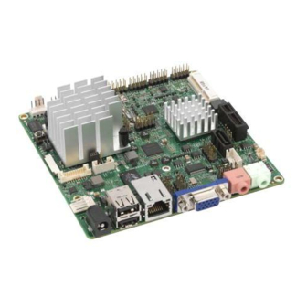
Chapter 1 Introduction Overview NITX-315/NITX-315-ET is a highly integrated Small Form Factor Nano-ITX board based on the Queensbay Platform, including the Tunnel Creek processor and Topcliff IOH. The NITX- 315/NITX-315-ET incorporates the standard processor, memory, graphics and I/O functionality, as is common as a small form factor PC motherboard. The NITX-315/NITX-315- ET operates with or without a local display. - Page 20 Introduction Table 1-1 Key Features of the NITX-315 (continued) Function Features SATA One internal SATA connector (7-pin) One standard 22 (15power+7signal) pins SATA connector for JEDEC MOS-297A internal slim lite SDD application MicroSD Card One Micro SD card slot ...
-
Page 21: Table 1-2 Key Features Of The Nitx-315-Et
Introduction Table 1-2 Key Features of the NITX-315-ET Function Features Processor Intel Tunnel Creek processor E640T 1.0GHz Single channel memory controller supporting DDR2 800 MT/s memory down Both LVDS up to 1280x768 @ 60Hz and SDVO output up to ... -
Page 22: Standard Compliances
Introduction Table 1-2 Key Features of the NITX-315-ET (continued) Function Features CAN bus One set of CAN bus on one 4-pin internal header Video One single-channel LVDS 20-pin header One VGA port derived from the SDVO port ... -
Page 23: Figure 1-1 Nitx-315 Declaration Of Conformity
We have an internal production control system that ensures compliance between the manufactured products and the technical documentation. ___________________________________________________ 08/26/2014 ______ Tom Tuttle, Manager, Product Testing Services Date (MM/DD/YYYY) NITX-315/NITX-315-ET Installation and Use (6806800L71D) -
Page 24: Mechanical Data
Introduction Mechanical Data 1.3.1 NITX-315/NITX-315-ET Mechanical Data Figure 1-2 NITX-315/NITX-315-ET Mechanical Data (Top View) 120.00 116.76 3.20 THROUGH HOLE WITH 5.5mm PAD BOTH SIDE 86.98 4 PLACE 3.00 3.00 0.00 NITX-315/NITX-315-ET Installation and Use (6806800L71D) -
Page 25: Figure 1-3 Nitx-315/Nitx-315-Et Mechanical Data (Side View)
Introduction Figure 1-3 NITX-315/NITX-315-ET Mechanical Data (Side View) 30.22 5.15 NITX-315/NITX-315-ET Installation and Use (6806800L71D) -
Page 26: Board Identification
Introduction Board Identification This section shows the serial number and its location on the board. Figure 1-4 Serial Number Location Ordering Information Use the order numbers below when ordering board variants or board accessories. NITX-315/NITX-315-ET Installation and Use (6806800L71D) -
Page 27: Board Variants
NANO ITX 1.0 GHz, ET 1.5.2 Board Accessories The following table lists the board accessories that are available upon release of this publication. Table 1-5 Available Board Accessories Order Number Description KR8-PS01 DC POWER ADAPTER 60W NITX-315/NITX-315-ET Installation and Use (6806800L71D) - Page 28 Introduction NITX-315/NITX-315-ET Installation and Use (6806800L71D)
-
Page 29: Hardware Preparation And Installation
Environmental and Power Requirements 2.1.1 Environmental Requirements The following tables list the environmental requirements that the NITX-315 and NITX-315-ET boards must meet when operated in your particular system configuration. Operating temperatures refer to the temperature of the air circulating around the board and not to the component temperature. -
Page 30: Thermal Requirements
.01 g^2/Hz @ 5-500Hz Shock 20g 11ms sine or saw Altitude -60 - 4000 m ASL 2.1.2 Thermal Requirements Table 2-3 Critical temperature Spots for NITX-315 and NITX-315-ET Maximum Allowable Component Identifier Heat Dissipation Power (W) Temperature (°C) CPU: 90 (Tj of Commercial... -
Page 31: Power Requirements
Use the handle and face plate, where applicable, or the board edge when removing the product from the enclosure. 2.1.3 Power Requirements The following table describes the power dissipation of the NITX-315 and NITX-315-ET board. Table 2-4 NITX-315 Power Dissipation State +12 V... -
Page 32: Unpacking And Inspecting The Board
Hardware Preparation and Installation Table 2-4 NITX-315 Power Dissipation (continued) State +12 V VCC_RTC Power consumption (w) 0.038A (unplug ethernet) 0.456w (unplug 0.155 A (plug ethernet) ethernet) 1.86w (plug ethernet) Unpacking and Inspecting the Board Read all notices and cautions prior to unpacking the product. -
Page 33: Preparing The Installation Environment
There are available spare parts of the components to be installed or replaced in the equipment warehouse. When the available spare parts are lacking, contact Artesyn Embedded Technologies for help in time. For details on how to get help from Artesyn Embedded Technologies, visit http://www.artesyn.com/computing/. -
Page 34: Board Thermal Management And Placement
Artesyn Embedded Technologies for technical support. Board Thermal Management and Placement NITX-315/NITX-315-ET provides a thermal management strategy. This includes CPU junction temperature monitoring, one on-board fan connector, and can take the corresponding action to protect the system during catastrophic overheating. -
Page 35: Table 2-5 Onboard Led Definition
LED D8 shows this status. Table 2-5 Onboard LED Definition Definition Status Description 'PROCHOT' signal is active The CPU temperature goes up to 110°C Normal status 'THERMTRIP#' signal is active The CPU temperature goes up to 125°C Normal status NITX-315/NITX-315-ET Installation and Use (6806800L71D) -
Page 36: Eusb Flash Disk Installation And Removal
Removing the eUSB Flash Disk from the Module 1. Loosen and remove the screws of the eUSB Flash disk from the standoff. 2. While holding the edges, pull the eUSB Flash disk from the board. NITX-315/NITX-315-ET Installation and Use (6806800L71D) -
Page 37: Sata Hdd And Slim Lite Ssd (Mo-297) Connection And Removal
Damage of Circuits Electrostatic discharge and incorrect module installation and removal can damage circuits or shorten their life. Before touching the module or electronic components, make sure that you are working in an ESD-safe environment. NITX-315/NITX-315-ET Installation and Use (6806800L71D) -
Page 38: Figure 2-3 J9 22-Pin Sata Connector
Hardware Preparation and Installation 1. Locate the J9 22-pin SATA connector on the underside of the NITX-315/NITX-315- ET board. Figure 2-3 J9 22-pin SATA connector 2. Connect one end of the SATA cable to the J9 22-pin SATA connector and the other end to the SATA HDD or SSD device. -
Page 39: Figure 2-5 Slim Lite Ssd (Mo-297)
Hardware Preparation and Installation Figure 2-5 Slim Lite SSD (MO-297) HDD or SDD device should be fastened to a chassis or an enclosure. NITX-315/NITX-315-ET Installation and Use (6806800L71D) - Page 40 Hardware Preparation and Installation NITX-315/NITX-315-ET Installation and Use (6806800L71D)
-
Page 41: Controls, Leds, And Connectors
Chapter 3 Controls, LEDs, and Connectors Board Layout Figure 3-1 NITX-315/NITX-315-ET Module Components NITX-315/NITX-315-ET Installation and Use (6806800L71D) -
Page 42: Figure 3-2 Nitx-315/Nitx-315-Et Module Components (Rear View)
Controls, LEDs, and Connectors Figure 3-2 NITX-315/NITX-315-ET Module Components (Rear View) NITX-315/NITX-315-ET Installation and Use (6806800L71D) -
Page 43: Connectors And Switches
S2 Switch Settings Table 3-1 S2 Switch Settings Signal PWR_SW 3.2.2 LVDS Header (P28) Table 3-2 LVDS Header Pin Definition (P28) Signal Signal VCC_LVDS VCC_LVDS LVDS_A_A0_P LVDS_A_CLK_P LVDS_A_A0_N LVDS_A_CLK_N LVDS_A_A1_P LDDC_CLK LVDS_A_A1_N LDDC_DATA LVDS_A_A2_P LVDS_A_A3_P LVDS_A_A2_N LVDS_A_A3_N NITX-315/NITX-315-ET Installation and Use (6806800L71D) -
Page 44: Lvds Backlight Header (P23)
Table 3-4 LVDS Power Connector Pin Definition Signal D33VS VCC_LVDS_SEL D50VS Table 3-5 LVDS Power Jumper Pin Definition Jumper setting (Jumper:P5) Configuration P5 (1-2) Using 3.3V to power the LVDS panel P5 (2-3) Using 5V to power the LVDS panel NITX-315/NITX-315-ET Installation and Use (6806800L71D) -
Page 45: Usb Client Header (P18)
USB power detect 3.2.6 CPU JTAG header (P20) - Optional Table 3-7 CPU JTAG Header Pin Definition Signal XDP_TDI CPU_TDI INT_TDI CPU_TDO IO_TDO XDP_TDO 3.2.7 USB Header (P6) Table 3-8 USB Header Pin Definition Signal USB0_PWR NITX-315/NITX-315-ET Installation and Use (6806800L71D) -
Page 46: Eusb Header (P2)
Controls, LEDs, and Connectors Table 3-8 USB Header Pin Definition (continued) Signal USB1_PWR USB0_DN USB1_DN USB0_DP USB1_DP dummy 3.2.8 eUSB Header (P2) Table 3-9 eUSB Pin Header Definition Signal USB4_PWR USB5_PWR USB4_DN USB5_DN USB4_DP USB5_DP dummy NITX-315/NITX-315-ET Installation and Use (6806800L71D) -
Page 47: Audio Header (P12)
Controls, LEDs, and Connectors 3.2.9 Audio Header (P12) Table 3-10 Audio Header Pin Definition Signal Dummy Dummy LOUT_R Dummy Dummy LOUT_L LOUT_JD 3.2.10 CAN Bus Header (P15) Table 3-11 CAN Bus Header Pin Definition Signal CAN_H CAN_L VCC5 NITX-315/NITX-315-ET Installation and Use (6806800L71D) -
Page 48: Spi Program Header (P21)
Table 3-12 SPI Program Header Pin Definition Signal V3V3_POWER SPI_CS SPI_CLK SPI_MISO SPI_MOSI 3.2.12 Full Wire RS232 Header (P7) Table 3-13 Full Wire RS232 Header Pin Definition Signal COM1A_DCD COM1A_RXD COM1A_TXD COM1A_DTR COM1A_DSR COM1A_RTS COM1A_CTS COM1A_RI- NITX-315/NITX-315-ET Installation and Use (6806800L71D) -
Page 49: Two Wire Rs232 Header (P14)
Controls, LEDs, and Connectors 3.2.13 Two Wire RS232 Header (P14) Table 3-14 Two Wire RS232 Header Signal COM2_RXD_232 COM2_TXD_232 COM3_RXD_232 COM3_TXD_232 COM4_RXD_232 COM4_RXD_232 3.2.14 SDIO Header (P16) Table 3-15 SDIO Header Pin Definition Signal DAT3 DAT0 DAT1 NITX-315/NITX-315-ET Installation and Use (6806800L71D) -
Page 50: Battery Header (P17)
Table 3-15 SDIO Header Pin Definition (continued) Signal DAT2 3.2.15 Battery Header (P17) Table 3-16 Battery Header Pin Definition Signal VBAT 3.2.16 Front Panel Header (P19) Table 3-17 Front Panel Header Pin Definition Signal HD_LED POWER_LED HD_LED_N PWRBTN RESET Dummy NITX-315/NITX-315-ET Installation and Use (6806800L71D) -
Page 51: Gpio Header (P4)
Table 3-17 Front Panel Header Pin Definition (continued) Signal 3.2.17 GPIO Header (P4) Table 3-18 GPIO Header Pin Definition Signal GPO0 GPI0 GPO1 GPI1 GPO2 GPI2 GPO3 GPI3 3.2.18 TPM Header (P8) Table 3-19 TPM Header (P8) Pin Definition Signal LPC_CLKOUT0 LPC_FRAME_N NITX-315/NITX-315-ET Installation and Use (6806800L71D) -
Page 52: Cpu Fan Header (P1)
Table 3-19 TPM Header (P8) Pin Definition (continued) Signal Dummy TPM_RST_N D50VS LPC_AD<3> LPC_AD<2> D33VS LPC_AD<1> LPC_AD<0> SMB_CLK SMB_DAT D33V LPC_SERIRQ TPM_CLKRUN_N TPM_LPCPD_N TPM_LDRQ0_N 3.2.19 CPU FAN Header (P1) Table 3-20 CPU FAN Header Pin Definition Signal D50VS TACH NITX-315/NITX-315-ET Installation and Use (6806800L71D) -
Page 53: Atx 4-Pin Power Header (J4)
Table 3-21 ATX 4-Pin Power Header Pin Definition Signal +12V +12V 3.2.21 SATA Power Header (P16) Table 3-22 SATA Power Header Pin Definition Signal +12V +3.3V 3.2.22 I2C Header (P9) Table 3-23 I2C Header Pin Definition Signal +3.3V I2C_CLK NITX-315/NITX-315-ET Installation and Use (6806800L71D) -
Page 54: 3.2.23 J9 Sata Connector
Controls, LEDs, and Connectors Table 3-23 I2C Header Pin Definition (continued) Signal I2C_DAT 3.2.23 J9 SATA Connector Table 3-24 J9 SATA Pin Definition Signal SATA_TXP SATA_TXN SATA_RXN SATA_RXP +3.3V +3.3V +3.3V RESERVED NITX-315/NITX-315-ET Installation and Use (6806800L71D) -
Page 55: Onboard Leds
Controls, LEDs, and Connectors Table 3-24 J9 SATA Pin Definition (continued) Signal +12V +12V +12V Onboard LEDs Table 3-25 Onboard LEDs Location Color Description Processor Hot Alert Thermal Trip Alert Green Power OK indicator NITX-315/NITX-315-ET Installation and Use (6806800L71D) - Page 56 Controls, LEDs, and Connectors NITX-315/NITX-315-ET Installation and Use (6806800L71D)
-
Page 57: Functional Description
Chapter 4 Functional Description Block Diagram Figure 4-1 Block Diagram for NITX-315/NITX-315-ET NITX-315/NITX-315-ET Installation and Use (6806800L71D) -
Page 58: Processor
Functional Description Processor NITX-315/NITX-315-ET is designed to support the Tunnel Creek processor. The features are detailed in the table below: Table 4-1 Tunnel Creek Processor Features Feature Description Low-Power Intel Architecture Core 600 MHz (Ultra Low Power SKU), 1.0 GHz (Mainstream SKU) and 1.3 GHz(Premium SKU) with related TDP 2.7, 3.1, 3.3 W... -
Page 59: System Memory
There are 8 1Gb X 8 data width DRAM chips which forms a two Rank total 1GB memory capacity topology. And for some low-end configuration, the DRAM chips can be configured as one Rank topology which is a 512MB solution. NITX-315/NITX-315-ET Installation and Use (6806800L71D) -
Page 60: Pci-E Port
Two SATA ports are routed to the connector from the Topcliff, the SATA rate is 3Gbps and supports AHCI. One port is a 7-pin SATA connector, another is a 15-power+7signals connector which is used for "Slim Lite SSD". NITX-315/NITX-315-ET Installation and Use (6806800L71D) -
Page 61: Microsd
Functional Description MicroSD There are two SDIO links in NITX-315/NITX-315-ET, Link1 is routed to a microSD slot. Link0 is routed to an inner header, see Table 3-15 on page Figure 4-3 SDIO Link Connection Diagram Ethernet Interfaces NITX-315/NITX-315-ET provides a 10/100/1000 Ethernet connecting to the connector RJ45 J1. -
Page 62: Usb Interface
PCIE slot. The function can be selected in the BIOS setup menu. The client USB port is routed to a header. The Following figure is the routing diagram. SeeTable 3-8 on page 45 Table 3-9 on page Figure 4-4 USB ports connections diagram NITX-315/NITX-315-ET Installation and Use (6806800L71D) -
Page 63: Usb Flash
A CAN bus integrated in the Topcliff, The features are: Supports CAN Protocol Version 2.0B Active Supports bit rate up to 1 Mbit/s Supports 32 message objects Each message object has its own mask (identifier/direction/extended/New Data) NITX-315/NITX-315-ET Installation and Use (6806800L71D) -
Page 64: 4.12 I2C Serial Interface And Devices
4.12 I2C Serial Interface and Devices There is one I2C compatible SMbus on the TNC. The following devices connect to the SMbus: One 1x PCI-E slot One Mini PCI-E slot Temperature sensor EMC2103 NITX-315/NITX-315-ET Installation and Use (6806800L71D) -
Page 65: Figure 4-6 Board I2C Device Connection Diagram
Table 4-2 I2C Device Address Device PCIEx1 Mini-PCIE EMC2103 PCA9557 LM80 Address Note1 Note2 The PCI-E x1 slot SMB address depends on the PCI-E x1 card. The Mini PCI-E card SMB address depends on the Mini PCI-E card NITX-315/NITX-315-ET Installation and Use (6806800L71D) -
Page 66: 4.13 Video Interface
3-12 on page 4.17 GPIO Configuration There are three parts of GPIO in NITX-315/NITX-315-ET, one is a user define GPIO which is generated from PCA9557PW. The second part GPIO is coming from the TNC and the 3rd part GPIO is derived from Topcliff. -
Page 67: Table 4-3 Tnc Gpio Definition
Low: USB port5 is routing to Mini PCI-E slot High : USB port5 is routing to eUSB slot GPIO1 GPIO2 GPIO3 GPIO4 GPIO5 Client USB power detect. Low: No Client USB power existence High: Client USB power existence NITX-315/NITX-315-ET Installation and Use (6806800L71D) - Page 68 Functional Description Table 4-4 Topcliff GPIO Configuration (continued) Name Function GPIO6 GPIO7 GPIO8 DRAM vendor. Low: SAMSUNG High: MICRON GPIO9 MEM capacity. Low: 1GB High: 512MB GPIO10 MEM freq. Low: 667MHz High: 800MHz GPIO11 NITX-315/NITX-315-ET Installation and Use (6806800L71D)
-
Page 69: 4.18 Clock Distribution
Functional Description 4.18 Clock Distribution The following figure displays the clock source used by NITX-315/NITX-315-ET: Figure 4-7 Clock Distribution of NITX-315/NITX-315-ET Table 4-5 Clock Assignments DEVICE CLOCK SIGNAL(S) FREQUENCY (MHz) CLOCK TREE SOURCE BCLK BU7335MWV DIFF HPLL_REFCLK BU7335MWV DIFF SDVO_REFCLK... - Page 70 1.8432/12 Crystal or BU7335MWV Single Topcliff IOH_CLK BU7335MWV DIFF Topcliff SATA0_CLK BU7335MWV DIFF Topcliff IOH_USB_CLK BU7335MWV Single Topcliff IOH_SYS_CLK BU7335MWV Single CLK_PCIE_LAN BU7335MWV DIFF PCIE slot CLK_PCIE_SLOT BU7335MWV DIFF Mini PCIE slot CLK_PCIE_MINICARD BU7335MWV DIFF NITX-315/NITX-315-ET Installation and Use (6806800L71D)
-
Page 71: Bios
If you exit Setup without saving any changes, the boot process continues with the search for a boot device. If the changes are saved, the motherboard loads the new settings and resets - re-starting the entire boot process. NITX-315/NITX-315-ET Installation and Use (6806800L71D) -
Page 72: Setup Utility
Serial Port settings Chipset Features including Host Bridge and Southbridge Boot Boot mode and Boot options Security Administrator's password Save & Exit Save with or without changes, Load/save default settings and Boot Device Selection NITX-315/NITX-315-ET Installation and Use (6806800L71D) -
Page 73: Table 5-2 Aptio Navigation
When you are in sub-menu, <Esc> allows you to exit to the upper menu. Function keys When other function keys become available, they are displayed at the right of the screen along with their intended function. NITX-315/NITX-315-ET Installation and Use (6806800L71D) -
Page 74: Main Menu
Figure 5-1 Main Menu Table 5-3 Main Menu Field Description Field Description BIOS Vendor BIOS vendor name. Core Version Aptio core version. Project Version Project name and its version. Build Date BIOS build date. Memory Information NITX-315/NITX-315-ET Installation and Use (6806800L71D) -
Page 75: Table 5-4 Platform Information
There is no default value. Access Level Show Administrator or User access level Table 5-4 Platform Information Field Description Tunnel Creek Version 02 (B1 Stepping) PUNIT Build Date May 24 2011 PUNIT Build Time 0:38:19 NITX-315/NITX-315-ET Installation and Use (6806800L71D) -
Page 76: Advanced Menu
CPU Configuration Parameters, see Table 5-8 on page 78 Watchdog Timer Configuration Enable or Disable Watchdog Timer Function (WDT) , see Table 5-9 on page 79 SDIO Configuration SDIO configuration Parameters, see Table 5-10 on page 79 NITX-315/NITX-315-ET Installation and Use (6806800L71D) -
Page 77: Table 5-6 Acpi Settings
"TPM Support OFF" or "NO TPM Hardware" based on the TPM hardware connection status. If TPM SUPPORT is set to "Enable", it will show the following information TPM Enable Status: Provides the current TPM Enable/Disable status information. Items: Disabled, Enabled. NITX-315/NITX-315-ET Installation and Use (6806800L71D) -
Page 78: Table 5-8 Cpu Configuration
Windows XP SP2, SuSE Linux 9.2, RedHat Enterprise 3 Update 3.) Default is "Enabled". Intel Virtualization When enabled, a VM can utilize the additional hardware capabilities provided by Vanderpool Technology. Default is "Disabled". C-States Enable/Disable C2 and above. Default is "Enabled". NITX-315/NITX-315-ET Installation and Use (6806800L71D) -
Page 79: Table 5-9 Watchdog Timer Configuration
EFI application. Default is "Enabled". EHCI Hand-off This is a workaround for OSes without EHCI hand-off support. The EHCI ownership change should be claimed by EHCI driver. Default is "Enabled". Mass Storage Devices: List the attached Mass Storage Devices. NITX-315/NITX-315-ET Installation and Use (6806800L71D) -
Page 80: Table 5-13 Emc2103 H/W Monitor
Table 5-14 on page 80 COM1(Pci Bus 2,Dev 10,Func2) Console Redirection Console Redirection Enable or Disable. Default is Disabled. Console Redirection Settings See later description COM2(Pci Bus 2,Dev 10,Func3) Console Redirection Console Redirection Enable or Disable. Default is Disabled. NITX-315/NITX-315-ET Installation and Use (6806800L71D) -
Page 81: Table 5-15 Com0 Console Redirection Settings
Selects serial port transmission speed. The speed must be matched on the other side. Long or noisy lines may require lower speeds. Items: 9600, 19200, 57600, 115200. Default is 115200. Data Bits Selects the data bits. Items: 7, 8. Default is 8. NITX-315/NITX-315-ET Installation and Use (6806800L71D) - Page 82 Terminal data. Items: Disabled, Enabled. Default is Disabled. Resolution 100x31 Enables or disables extended terminal resolution. Items: Disabled, Enabled. Default is Enabled. Legacy OS Redirection On Legacy OS, the Number of Rows and Columns supported redirection. Items: 80x24, 80x25. Default is 80x24. NITX-315/NITX-315-ET Installation and Use (6806800L71D)
-
Page 83: Chipset Menu
Table 5-17 on page 83 South Bridge Chipset Configuration South Bridge Parameters, see Table 5-19 on page 84 IOH Configuration IOH Configuration Options Table 5-17 North Bridge Chipset Configuration Field Description North Bridge Chipset Configuration NITX-315/NITX-315-ET Installation and Use (6806800L71D) -
Page 84: Table 5-1 Table
Table 5-19 South Bridge Chipset Configuration Field Description South Bridge Chipset Configuration USB MUX Switch Configure the USB MUX setting, switch to Mini-PCIE or USB header. Items: Mini-PCIE Slot, USB Header. Default is USB Header. NITX-315/NITX-315-ET Installation and Use (6806800L71D) -
Page 85: Table 5-20 Pci Express Ports Configuration > Pci Express Root Port
Enable/Disable the WOL, Default is Disabled. WOL Mode Select WOL Mode. Items: Wake Up Frame, Magic packet. Default is the Wake Up Frame. WOL Speed Select the WOL Speed. Items: 10 Mbps, 100 Mbps, 1000 Mbps. Default is 10 Mbps. NITX-315/NITX-315-ET Installation and Use (6806800L71D) -
Page 86: Boot Menu
GateA20 Active UPON REQUEST - GA20 can be disabled using BIOS services. ALWAYS - do not allow disabling GA20; this option is useful when any RT code is executed above 1MB. Default is Upon Request. NITX-315/NITX-315-ET Installation and Use (6806800L71D) - Page 87 Set display mode for Option ROM. Items: Force BIOS, Keep Current. Default is Force BIOS. Interrupt 19 Capture Enabled: Allows Option ROMs to trap Int 19. Items: Enabled, Disabled. Default is Disabled. Boot Option Priorities Sets the system boot order. NITX-315/NITX-315-ET Installation and Use (6806800L71D)
-
Page 88: Security Menu
BIOS 5.4.5 Security Menu Figure 5-5 Security Menu Table 5-24 Security Menu Field Description Field Description Setup Administrator Sets the setup administrator password. Password User Password Sets the setup user password. NITX-315/NITX-315-ET Installation and Use (6806800L71D) -
Page 89: Save And Exit Menu
Exit system setup after saving the changes. Discard Changes and Exit Exit system setup without saving any changes. Save Changes and Reset Reset the system after saving the changes. Discard Changes and Reset Reset system setup without saving any changes. NITX-315/NITX-315-ET Installation and Use (6806800L71D) -
Page 90: Post Codes
0x50 - 0x5F PEI errors 0x60 - 0xCF DXE execution up to BDS 0xD0 - 0xDF DXE errors 0xE0 - 0xE8 S3 Resume (PEI) 0xE9 - 0xEF S3 Resume errors (PEI) 0xF0 - 0xF8 Recovery (PEI) NITX-315/NITX-315-ET Installation and Use (6806800L71D) -
Page 91: Standard Status Codes
North Bridge initialization after microcode loading South Bridge initialization after microcode loading OEM initialization after microcode loading Cache initialization SEC Error Codes 0xC - 0xD Reserved for future AMI SEC error codes Microcode not found Microcode not loaded NITX-315/NITX-315-ET Installation and Use (6806800L71D) -
Page 92: Pei Status Codes
OEM pre-memory initialization codes 0x2B Memory initialization. Serial Presence Detect (SPD) data reading 0x2C Memory initialization. Memory presence detection 0x2D Memory initialization. Programming memory timing information 0x2E Memory initialization. Configuring memory 0x2F Memory initialization (other). NITX-315/NITX-315-ET Installation and Use (6806800L71D) - Page 93 Post-Memory South Bridge initialization (South Bridge module specific) 0x3F-0x4E OEM post memory initialization codes 0x4F DXE IPL is started PEI Error Codes 0x50 Memory initialization error. Invalid memory type or incompatible memory speed 0x51 Memory initialization error. SPD reading has failed NITX-315/NITX-315-ET Installation and Use (6806800L71D)
- Page 94 0xE9 S3 Resume PPI not Found 0xEA S3 Resume Boot Script Error 0xEB S3 OS Wake Error 0xEC-0xEF Reserved for future AMI error codes Recovery Progress Codes 0xF0 Recovery condition triggered by firmware (Auto recovery) NITX-315/NITX-315-ET Installation and Use (6806800L71D)
-
Page 95: Pei Beep Codes
Memory not Installed Memory was installed twice (InstallPeiMemory routine in PEI Core called twice) DXEIPL was not found DXE Core Firmware Volume was not found Reset PPI is not available Recovery failed S3 Resume failed NITX-315/NITX-315-ET Installation and Use (6806800L71D) -
Page 96: Dxe Status Codes
South Bridge DXE Initialization (South Bridge module specific) 0x75 South Bridge DXE Initialization (South Bridge module specific) 0x76 South Bridge DXE Initialization (South Bridge module specific) 0x77 South Bridge DXE Initialization (South Bridge module specific) NITX-315/NITX-315-ET Installation and Use (6806800L71D) - Page 97 0xA0 Reserved for ASL (see ASL Status Codes section below) 0xA1 IDE initialization is started 0xA2 IDE Reset 0xA3 IDE Detect 0xA4 IDE Enable 0xA5 SCSI initialization is started 0xA6 SCSI Reset 0xA7 SCSI Detect NITX-315/NITX-315-ET Installation and Use (6806800L71D)
- Page 98 Some of the Architectural Protocols are not available 0xD4 PCI resource allocation error. Out of Resources 0xD5 No Space for Legacy Option ROM 0xD6 No Console Output Devices are found 0xD7 No Console Input Devices are found NITX-315/NITX-315-ET Installation and Use (6806800L71D)
-
Page 99: Dxe Beep Codes
Reset protocol is not available 5.5.2.6 CPU Exception Status Codess Table 5-32 CPU Exception Status Codes Status Code Description 0x00 Divide error 0x01 CPU Debug exception 0x02 Non maskable hardware Interrupt occurred 0x03 INT 3 breakpoint NITX-315/NITX-315-ET Installation and Use (6806800L71D) -
Page 100: Asl Status Codes
Table 5-33 ASL Status Codes Status Code Description 0x01 System is entering S1 sleep state 0x02 System is entering S2 sleep state 0x03 System is entering S3 sleep state 0x04 System is entering S4 sleep state NITX-315/NITX-315-ET Installation and Use (6806800L71D) -
Page 101: Oem-Reserved Status Code Ranges
0x80 - 0x8F OEM DXE initialization codes 0xC0 - 0xCF OEM BDS initialization codes Boot Order Support The boot firmware shall be capable of booting an image from eUSB flash, MicroSD and SATA- attached hard disk. NITX-315/NITX-315-ET Installation and Use (6806800L71D) -
Page 102: Windows Xp Installation
To update the BIOS, follow the steps listed below: 1. Prepare a dos bootable USB thumb drive. 2. Get the BIOS flash tool (AFUDOS) from the BIOS vendor. 3. Copy the AFUDOS and BIOS ROM file into the USB thumb drive. NITX-315/NITX-315-ET Installation and Use (6806800L71D) - Page 103 6. Select the USB thumb drive as the first boot device. 7. Save and reset, then the board will boot from the USB thumb drive. 8. Run the command AFUDOS BIOS.ROM /P /B /N /R to flash the BIOS. NITX-315/NITX-315-ET Installation and Use (6806800L71D)
- Page 104 BIOS NITX-315/NITX-315-ET Installation and Use (6806800L71D)
-
Page 105: Operating System And Driver Support
Chapter 6 Operating System and Driver Support Supported Operating Systems This module supports the following operating systems: Microsoft Window XP Professional Microsoft Window 7 Microsoft Windows Embedded Standard 2007 MeeGo Linux NITX-315/NITX-315-ET Installation and Use (6806800L71D) - Page 106 Operating System and Driver Support NITX-315/NITX-315-ET Installation and Use (6806800L71D)
-
Page 107: Replacing The Battery
Appendix A Replacing the Battery Replacing the Battery The battery location is shown in the following figure. Figure A-1 Battery Location NITX-315/NITX-315-ET Installation and Use (6806800L71D) -
Page 108: Replacing The Battery
The battery provides data retention of seven years summing up all periods of actual data use. Artesyn Embedded Technologies therefore assumes that there usually is no need to exchange the battery except, for example, in case of long-term spare part handling. -
Page 109: Related Documentation
The publications listed below are referenced in this manual. You can obtain electronic copies of Artesyn Embedded Technologies - Embedded Computing publications by contacting your local Artesyn sales office. For released products, you can also visit our Web site for the latest copies of our product documentation. - Page 110 Related Documentation NITX-315/NITX-315-ET Installation and Use (6806800L71D)
-
Page 111: Safety Notes
Artesyn intends to provide all necessary information to install and handle the product in this manual. Because of the complexity of this product and its various uses, we do not guarantee that the given information is complete. - Page 112 Changes or modifications not expressly approved by Artesyn Embedded Technologies could void the user's authority to operate the equipment. Board products are tested in a representative system to show compliance with the above mentioned requirements.
- Page 113 Verify that the length of an electric cable connected to a TPE bushing does not exceed 100 meters. Make sure the TPE bushing of the system is connected only to safety extra low voltage circuits (SELV circuits). If in doubt, ask your system administrator. NITX-315/NITX-315-ET Installation and Use (6806800L71D)
- Page 114 When exchanging the onboard lithium battery, make sure that the new and the old battery are exactly the same battery models. If the respective battery model is not available, contact your local Artesyn sales representative for the availability of alternative, officially approved battery models.
-
Page 115: Sicherheitshinweise
Installieren Sie keine Ersatzteile oder führen Sie keine unerlaubten Veränderungen am Produkt durch, sonst verfällt die Garantie. Wenden Sie sich für Wartung oder Reparatur bitte an die für Sie zuständige Geschäftsstelle von Artesyn Embedded Technologies. So stellen Sie sicher, dass alle sicherheitsrelevanten Aspekte beachtet werden. - Page 116 Sicherheitshinweise Das Produkt wurde in einem Artesyn Standardsystem getestet. Es erfüllt die für digitale Geräte der Klasse B gültigen Grenzwerte in einem solchen System gemäß den FCC-Richtlinien Abschnitt 15 bzw. EN 55022 Klasse B. Diese Grenzwerte sollen einen angemessenen Schutz vor Störstrahlung beim Betrieb des Produktes in Gewerbe- sowie Industriegebieten...
- Page 117 Sie, dass das Face Plate oder die Platine deformiert oder zerstört wird. Beschädigung des Produktes und von Zusatzmodulen Fehlerhafte Installation von Zusatzmodulen, kann zur Beschädigung des Produktes und der Zusatzmodule führen. Lesen Sie daher vor der Installation von Zusatzmodulen die zugehörige Dokumentation. NITX-315/NITX-315-ET Installation and Use (6806800L71D)
- Page 118 Verwenden Sie deshalb nur den Batterietyp, der auch bereits eingesetzt wurde und befolgen Sie die Installationsanleitung. Datenverlust Wenn Sie die Batterie austauschen, können die Zeiteinstellungen verloren gehen. Eine Backupversorgung verhindert den Datenverlust während des Austauschs. Wenn Sie die Batterie schnell austauschen, bleiben die Zeiteinstellungen möglicherweise erhalten. NITX-315/NITX-315-ET Installation and Use (6806800L71D)
- Page 119 Batteriehalter beschädigt werden. Um Schäden zu vermeiden, sollten Sie keinen Schraubendreher zum Ausbau der Batterie verwenden. Umweltschutz Entsorgen Sie alte Batterien und/oder Blades/Systemkomponenten/RTMs stets gemäß der in Ihrem Land gültigen Gesetzgebung, wenn möglich immer umweltfreundlich. NITX-315/NITX-315-ET Installation and Use (6806800L71D)
- Page 120 Sicherheitshinweise NITX-315/NITX-315-ET Installation and Use (6806800L71D)
- Page 122 Artesyn Embedded Technologies, Artesyn and the Artesyn Embedded Technologies logo are trademarks and service marks of Artesyn Embedded Technologies, Inc. All other product or service names are the property of their respective owners. © 2014 Artesyn Embedded Technologies, Inc.
Need help?
Do you have a question about the NITX-315 and is the answer not in the manual?
Questions and answers