Table of Contents
Advertisement
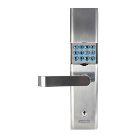
Installation Instructions & User Guide:
Wireless Keypad Lock LE162
PLEASE NOTE
Keep the below information in a safe and secure place for future reference.
IMPORTANT INFORMATION
Lock Programming Code
Six (6) digits
For security reasons, this code is chosen randomly and not held
on any database. If this code is lost, Customer Support will be
unable to assist. It is suggested you hold this code in a safe and
secure location, or change the code to your own, unique number.
1
Advertisement
Table of Contents

Related Manuals for Schlage LE162


Summary of Contents for Schlage LE162
- Page 1 If this code is lost, Customer Support will be unable to assist. It is suggested you hold this code in a safe and Installation Instructions & User Guide: secure location, or change the code to your own, unique number. Wireless Keypad Lock LE162...
-
Page 3: Table Of Contents
Installation Instructions & User Guide: Wireless Keypad Lock LE162 CONTENTS Contents of the box .................. 2 How to install your lock ................3 - Door preparation ..................- Lock installation ................9 - Template (see inside back cover) ........... IBC Lock Parts .................... -
Page 4: Contents Of The Box
CONTENTS OF THE BOX TOOLS NEEDED Phillips Screwdriver Side Cutters Tape Measure Pencil Drill (3mm, 12mm, 54mm Hole Saw Chisel Hammer 25mm bits) -
Page 5: How To Install Your Lock
HOW TO INSTALL YOUR LOCK 1. Door preparation 32mm-45mm 1.1 Measure door width. If the door is thinner than 32mm or thicker than 45mm, then the lock will not fit properly on the door. Door face Door edge 1.2 Mark lock centre line on door face and door edge. Recommend between 1040mm and 1100mm from floor. - Page 6 1. Door preparation (continued). 1.3 Mark and drill 54mm and 12mm holes. (See inside back cover for template). 30mm 60mm 100mm 95mm 12mm drill bit 54mm hole saw 32mm-45mm...
- Page 7 1.4 Mark and drill 25mm hole in door edge. ½ door width 25mm drill bit...
- Page 8 1. Door preparation (continued).
- Page 9 1.5 Measure and mark door jamb for strike. Door jamb Recommended between 1040mm and 1100mm from floor Latch hole Recommended between 1040mm and 1100mm from floor Measure from floor and mark on door jamb. Mark centre for strike hole exactly opposite latch hole.
- Page 10 1. Door preparation (continued). 12mm drill bit As shown, chisel a hole in marked area, depth of 15mm. Line up dust box and strike with hole in door jamb. Use pencil to trace strike and mark holes. Drill two (2) 3mm pilot holes and use chisel to create strike mortice, 2mm deep. Position dust box and strike and screw into place.
-
Page 11: Lock Installation
2. Lock installation Install the latch according to the direction the door opens/closes. - Page 12 2. Lock installation (continued). For exterior and interior lock body: 2.1 Remove the o-ring (for interior lock body only. Exterior lock body screw can be located in screw bag). 2.2 Slide lever over spigot, ensuring lever points towards door hinges. 2.3 Fasten the screws with the Allen Key provided.
- Page 13 2. Lock installation (continued). 2.4 Insert ball bearing end of the spindle into interior lock body. 2.5 Place interior lock body on the door ensuring the spindle locates through the latch and the cable is threaded through the hole, under the latch.
- Page 14 5. Install exterior lock body. Vertical Weather Seal Cylinder Driver 5.1 Remove the cylinder driver from its packet and attach it to its nodule located near the bottom of the exterior lock body. Spin the cylinder driver until the lip is under the screw. 5.2 Adjust/spin the ‘female’...
- Page 15 6. Mount the lock. Mounting Mounting screws 1 & 2 screws 1 & 2 Suit >42mm Suit 35-42mm Suit 32-35mm Mounting screw 3 Suit >37mm Suit 32-37mm Mounting screw 3 6.1 Cut the screws to suit the door thickness. 6.2 Screw mounting screws until tight (do not use a power drill).
- Page 16 7. Batteries. Place the batteries as the diagram shows. The default setting for the lock is DEADLOCKED mode. Please read page 18 for more details. Default setting is Deadlocked mode. It will lock both internally and externally. To unlock, enter your user code on the external keypad or use the key. See page 18 for more details.
-
Page 17: Lock Parts
LOCK PARTS Lock button Lock/unlock light Keypad Unlock button Lever Latch Key/cylinder Keypad • Located on the outside of the lock. • Use to enter codes for manual programming and unlocking. Lever • The inside lever can be rotated at any time to retract the latch (except in DEADLOCKED mode). Cylinder •... -
Page 18: Codes
PROGRAMMING AND USER CODES All locks are pre-programmed with a programming code and two user codes. The programming code and user codes can be changed at any time. All pre-programmed codes can be found on the yellow sticker on the front of the Installation Instructions that come with the lock. -
Page 19: Manual Programming Codes
MANUAL PROGRAMMING CODES If the solution access is temporarily lost, changes to the lock can be entered manually at the lock’s keypad. See Manual Programming Functions on the inside front cover for more information. Lights/Beeps Legend Step Confirmation: Three lights and A correct entry was made during programming three beeps and accepted by the lock. -
Page 20: Functions
OPERATING BUTTONS This lock has three operating modes - Deadlocked / Locked / Unlocked • DEADLOCKED: User code or key needed to open from both inside or outside. (Please note this setting locks both internally and externally. To unlock, input user code into external keypad or use key). -
Page 21: Restoring Factory Settings
RESTORING FACTORY SETTINGS Restoring the factory settings will: • Restore the original programming code • Restore the pre-programmed user codes DO NOT reset your lock unless you are able to locate the original programming code Customer service cannot retrieve a lost programming code. To restore factory settings: •... -
Page 22: Emergency Override Key
EMERGENCY KEY OVERRIDE If the batteries need changing the red light on the lock will flash continuously as a warning. A battery indicator is also shown on most user interfaces (refer solution provider for details.) If the battery fails completely, or if there is an electronic error, the lock can be unlocked manually using the key. -
Page 23: Troubleshooting
TROUBLESHOOTING Problem Lights/ Cause Solution Beeps at Lock Entering a valid user Green then Lock is in vacation mode Enter six-digit programming code using the keypad Red/High code does not unlock lock then Low Buttons do not light up None Lock keypad is locked out Wait 30 seconds and try when pressed... - Page 24 TROUBLESHOOTING (continued) Problem Lights/ Cause Solution Beeps at Lock Cannot change User code already in lock Select a different programming matches the first four digits of the code, or delete the user code programming programming code you are trying that matches the first four digits code to add you want to use...
-
Page 25: Glossary
Problem Lights/ Cause Solution Beeps at Lock Water is Various The lock is not air tight externally This lock may be permanently found inside possibilities or rain/water is reaching the lock damaged, but removing the lock the lock, or internally. from the door and leaving it to condensation dry for 24 hours may restore it... - Page 26 Allegion (Australia) Pty Ltd Allegion (New Zealand) Limited Phone 1800 098 094 Phone 0800 477 869 Website www.allegion.com.au Website www.allegion.co.nz January 2014...
- Page 27 100mm 95mm...
Need help?
Do you have a question about the LE162 and is the answer not in the manual?
Questions and answers