Kemppi Master S 400 Service Manual
Hide thumbs
Also See for Master S 400:
- Operating instructions manual (20 pages) ,
- Quick manual (8 pages)
Table of Contents
Advertisement
Advertisement
Table of Contents

Related Manuals for Kemppi Master S 400


Summary of Contents for Kemppi Master S 400
-
Page 1: Service Manual
SERVICE MANUAL Master S 400 Kemppi Oy... -
Page 2: Table Of Contents
4.2.1. Rectifier and IGBT modules ......................18 4.2.2. Secondary rectifier ........................... 18 4.2.3. Secondary power rail ........................18 4.3. Calibration procedure ..........................19 4.4. Final testing ............................. 20 4.4.1. Load bank test ..........................20 4.4.2. Test welding ............................. 21 5. NOTES ................................22 Kemppi Oy... -
Page 3: Read This First
Service manual Master S 400 and 500 Version 1.1 5.9.2014 1. READ THIS FIRST 560VDC or higher are inside the machine Before removing any covers or commencing any testing or measurement disconnect the power source from the mains voltage Dangerous DC voltage may still exist after the removal of the input voltage. Machine discharges the voltage while it is turned off, but it is always better to ensure this by measuring the voltage Wait at least one minute for the capacitors to become discharged. -
Page 4: General
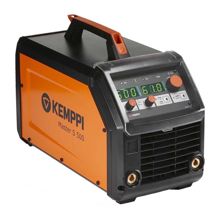
Service manual Master S 400 and 500 Version 1.1 5.9.2014 2. GENERAL Master family has a high quality DC MMA welding sources for industrial applications. Current range is 30-400A for 400A model and 30-500A for 500A model ... -
Page 5: Wiring Diagram
Service manual Master S 400 and 500 Version 1.1 5.9.2014 3.2. Wiring diagram Latest version with better quality is available at Kemppi Channel. Kemppi Oy... -
Page 6: Construction
Service manual Master S 400 and 500 Version 1.1 5.9.2014 3.3. Construction Back Front Left side Right side Panel Left side Kemppi Oy... -
Page 7: Assembly
Service manual Master S 400 and 500 Version 1.1 5.9.2014 3.4. Assembly 1.Cellu coil (optional) 2. Secondary rail 3. Z002 secondary rectifier 4. Main transformer 5. Z001 main circuit card 6. Primary heat sink support/insulator Kemppi Oy... -
Page 8: S 400 Z001 Main Circuit Card Structure
Service manual Master S 400 and 500 Version 1.1 5.9.2014 3.4.1. S 400 Z001 main circuit card structure 1. Input varistors 2. Input rectifier protection circuit 3. DC-link capacitors 4. Input rectifier (on the other side) 5. IGBT (on the other side) 6. -
Page 9: S 500 Z001 Main Circuit Card Structure
Service manual Master S 400 and 500 Version 1.1 5.9.2014 3.4.2. S 500 Z001 main circuit card structure 1. Input rectifier protection circuit 2. DC-link capacitors 3. Input rectifier (on the other side) 4. IGBT (on the other side) 5. Control circuitry 7. -
Page 10: P001 Panel Card Structure
Service manual Master S 400 and 500 Version 1.1 5.9.2014 3.4.3. P001 Panel card structure 1. Pulse potentiometer 2. 7-segment displays for voltage 3. X1 Flat cable connector 4. 7-segment displays for current 5. Power on LED 6. Overheat LED 7. -
Page 11: Description Of Operation
Service manual Master S 400 and 500 Version 1.1 5.9.2014 3.5. Description of operation Master S is divided in to six functional parts Z001 main circuit card with control circuitry Over voltage protection IGBT based power section with full bridge architecture. Switching frequency is dual mode: 50kHz in low and 20kHz in higher output power. -
Page 12: Setup Functions And Error Codes
Service manual Master S 400 and 500 Version 1.1 5.9.2014 3.6. Setup functions and error codes 3.6.1. Setup functions and menu Setup can be entered by pressing “Remote” button as long as text “Set” appears in the display. Parameters can be browsed with potentiometer and by pressing shortly “Remote” button parameter value can be adjusted by potentiometer. -
Page 13: Error Codes And Error Log Menu
Service manual Master S 400 and 500 Version 1.1 5.9.2014 3.6.2. Error codes and error log menu Machine can show several error codes and they are automatically saved to error log file. This log file can save up to 10 errors. -
Page 14: Erasing Error Log
Service manual Master S 400 and 500 Version 1.1 5.9.2014 For example: latest error was Primary over voltage: 0.E3 one before that was phase watch error: 1.E9 No more error in the log, so other error rows are empty: 2.E-, 3.E-, 4.E- and so on Error log can be exited whenever by long pressing the A/V button. - Page 15 Service manual Master S 400 and 500 Version 1.1 5.9.2014 Resetting the calibration data to factory values: Rotate potentiometer until “FAC” appears in the display and select it with short press of “A/V” button, display shows “OFF”. Change value with potentiometer to “rES” and when exiting the calibration state by long pressing A/V button, calibration data will be reset.
-
Page 16: Service Instructions
Service manual Master S 400 and 500 Version 1.1 5.9.2014 4. SERVICE INSTRUCTIONS 4.1. Measurements and tests Master has only few measurements that can be done because control circuitry is integrated to Z001 card and panel does have only potentiometer and few press buttons. - Page 17 Service manual Master S 400 and 500 Version 1.1 5.9.2014 IGBT module IGBT IGBT module has 4 IGBTs and each one of these has diode in parallel. Module has also integrated NTC thermistor for overheat protection. Parallel diode Check the diodes using the multimeter diode function to measure their threshold voltage. Diodes must be measured both forward bias and reverse bias condition to make sure they are ok.
-
Page 18: Overheat Protection
Service manual Master S 400 and 500 Version 1.1 5.9.2014 IGBT diode Positive test lead Negative test lead Result IGBT 1 Output 1 DC-link positive 0,2-0,7VDC IGBT 2 Output 2 DC-link positive 0,2-0,7VDC IGBT 3 Ground Output 1 0,2-0,7VDC IGBT 4... -
Page 19: Secondary Rectifier
The cooling fans are installed so that the air flows from the back to the left side of the chassis. Air comes out through the front plate grill. Air deflector must be installed for proper cooling. 4.1.4. Safety tests Safety tests are made normally. See the separate document for safety tests in Kemppi Channel. Kemppi Oy... -
Page 20: Semiconductor Installation
Service manual Master S 400 and 500 Version 1.1 5.9.2014 4.2. Semiconductor installation It is a must be to use torque screwdriver while tightening any power components onto the heat sink. See following sections for tightening torques. 4.2.1. Rectifier and IGBT modules Master S has soldered rectifier and IGBT modules and it is not possible to change them separately. -
Page 21: Calibration Procedure
Service manual Master S 400 and 500 Version 1.1 5.9.2014 4.3. Calibration procedure Calibration is not normally needed to be done. Spare part cards are calibrated in factory and will keep their range while installed in to the machine. If calibration parameters are accidentally modified, they can be restored by selecting parameter FAC in the end of calibration menu. -
Page 22: Final Testing
Service manual Master S 400 and 500 Version 1.1 5.9.2014 4.4. Final testing After the machine repair and low voltage tests, it is good practice to carry out some load tests and finish with some test welds. Only then is it possible to guarantee the machine is working correctly. -
Page 23: Test Welding
Service manual Master S 400 and 500 Version 1.1 5.9.2014 4.4.2. Test welding Test welding is important for having final and reliable information, if the maintenance / repair has been made successfully. In some cases a load bank test alone does not give the absolute truth if the machine is functioning properly or not. -
Page 24: Notes
Service manual Master S 400 and 500 Version 1.1 5.9.2014 5. NOTES Kemppi Oy...
Need help?
Do you have a question about the Master S 400 and is the answer not in the manual?
Questions and answers