Table of Contents
Advertisement
Quick Links
Advertisement
Table of Contents

Related Manuals for SMAR TP301


Summary of Contents for SMAR TP301
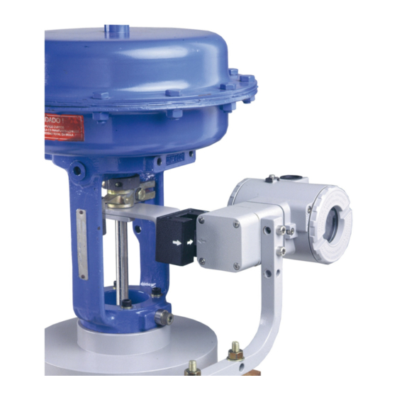
- Page 3 The magnetic coupler replacing the mechanical connection, results in a clear reduction of the deadband. TP301 can be set up in any linear or rotary valve, actuator or a variety of other equipment, such as floodgate skylight, dampers, rolls mill height, crusher, etc.
- Page 4 Smar provides specific training to instruct and qualify such professionals. However, each country must comply with the local safety procedures,...
-
Page 5: Table Of Contents
Installation Flowchart TABLE OF CONTENTS SECTION 1 - INSTALLATION ........................1.1 GENERAL..................................1.1 MOUNTING .................................. 1.1 ELECTRONIC HOUSING ROTATING ......................... 1.7 ELECTRIC WIRING ..............................1.7 RECOMMENDATIONS FOR MOUNTING APPROVED EQUIPMENTS WITH THE IP66/68 W CERTIFICATIONS (“W" INDICATES CERTIFICATION FOR USE IN SALINE ATMOSPHERES) ............1.9 ROTARY AND LINEAR MAGNET .......................... - Page 6 TP301 – Operation, Maintenance and Instructions Manual Installation Flowchart Start Has the transmitter been configured Field Installation. on the bench for the application ? Verify the area classification and its related practices (Section 1). Configure the transmitter ( section 1 and section 3).
-
Page 7: Section 1 - Installation
Although the transmitter is virtually insensitive to vibration, installation close pumps, turbines or other vibrating equipment should be avoided. Mounting The TP301 mounting depends on the type movement, linear or rotary. Two brackets are required for mounting, one for the magnet and the other for the transmitter itself. NOTE Make sure that arrow engraved on the magnet coincides with the arrow engraved on the Position Transmitter when the system is in mid travel. - Page 8 TP301 – Operation, Maintenance and Instructions Manual The following Figures 1.1 and 1.3 show both linear and rotary typical mounting: Rotary Movement Install the magnet on the valve stem using the magnet mounting bracket. ROTATY POSITIONER ROTARY POSITIONER MAGNET TRANSMITTER...
- Page 9 Installation Linear Movement Install the magnet on the valve stem using the magnet mounting bracket. The linear magnet movement must be orthogonal in relation to the main axis of the position transmitter. For example, if the linear magnet movement is vertical, the transmitter main axis must be horizontal, as show in Figure 1.3.
- Page 10 TP301 – Operation, Maintenance and Instructions Manual “L” BRACKET WITH “U” CLAMP FOR REMOTE SENSOR LINEAR MAGNET BRACKET REMOTE POSITION TRANSMITTER VALVE YOKE M6x1 SCREWS VALVE (2 PLACES) STEM LINEAR M6 x 1 SCREWS MAGNET (2 PLACES) CENTRALIZER DEVICE “L” BRACKET WITH “U”...
- Page 11 Installation See below the TP301, dimensional drawings. Figure 1.5 – TP301 Dimensional Drawing / Magnets Dimensional Drawing...
- Page 12 TP301 – Operation, Maintenance and Instructions Manual REMOTE SENSOR Leave, at least, a 150 mm space, for zero and span adjustment with the THREADS FOR SCREWS (4.45) 49.5 PLUG magnetic tool. M6 x 1 ( 2 PLACES ) (1.95) (0.35)
-
Page 13: Electronic Housing Rotating
Installation Electronic Housing Rotating The electronic housing rotates for a better digital display reading. To rotate it, release the housing rotation screw. Figure 1.6 - Cover Locking and Housing Rotation Set Screw Figure 1.7 - Cover Locking Screw Electric Wiring The digital display also rotates for better reading. - Page 14 ANY POINT OR LEFT UNGROUNDED. Figure 1.9 - TP301 Wiring Diagram The Figure 1.10 shows a typical TP301 connection in multidrop configuration. Such configurations allow a maximum of 15 transmitters on the same line connected in parallel. Take care to the power supply capacity as well, when many transmitters are connected on the same line.
-
Page 15: Recommendations For Mounting Approved Equipments With The Ip66/68 W Certifications ("W" Indicates Certification For Use In Saline Atmospheres)
(“W" indicates certification for use in saline atmospheres) NOTE This TP301 certification is valid for stainless steel transmitter manufactured, approved with the certification IP66/68 W. All transmitter external material, such as plugs, connections etc., should be made in stainless steel. -
Page 16: Remote Position Sensor
(maximum limit 20 (meters) length), keep it away from possible sources of induction and/or magnetic interference. The cable supplied by Smar is shielded with excellent protection against electromagnetic interference, but despite of this protection, it is recommended to avoid the cable sharing the same conduit with other cables. -
Page 17: Installation In Hazardous Areas
Installation Installation in Hazardous Areas Consult the Appendix A for Hazardous Location Approvals. 1.11... - Page 18 TP301 – Operation, Maintenance and Instructions Manual 1.12...
-
Page 19: Section 2 - Operation
Functional Description - Electronics The function of each block in the block diagram is described below. Figure 2.1 - TP301 Block Diagram Hall Effect Position Sensor The magnet, installed in the instrument to the position to be measured, moves the of the instrument movement accordingly. -
Page 20: Local Indicator
3.6 mA; during operation, consumption may be as high as 21 mA, depending on the measurement and sensor status. If configured for low signal failure, the TP301 shows 3.6 mA indication if configured for high signal failure, it shows 21 mA indication;,3.8 mA in the case of low saturation;... -
Page 21: Section 3 - Configuration
® The TP301 is configured via Local Adjust or configurators with digital communication (HART Protocol). It is also possible to configure the TP301 via the CONF401 configuration tool or any FDT/DTM software application, both for desk or laptop. To enable local adjustment, the jumper “W1" located on top of the main board shall be connected to the pins where the word “ON”... -
Page 22: Local Adjust
TP301 – Operation, Maintenance and Instructions Manual Figure 3.2 - W2 and W1 Jumpers Local Adjustment Local Configuration Tree The Local Adjustment Configuration Tree, as per Figure 3.3, shows possesses the available functions in the equipment. Step 1 To configure the functions, it is enough to maintain the magnetic tool in Z; in that way it will browse all the available functions. - Page 23 Local Adjustment Programming Action Ação Rotation Rotação UpPos Unit Damp LoPos Pprc Actr execute execute Actd execute execute Figure 3.3 – Local Adjustment Configuration Tree Description of the Parameters of the Local Adjustment Configuration Tree POS – Position in Percentage UNIT Engineering Unit or Percentage.
-
Page 24: Procedure To Calibrate The Position Transmitter
(see the programming tree at the configurator manual). Configuration via Configurators TP301 can be configured through the manual portable configurator portable manual based on PalmOS platform. Besides, the TP301 has connectivity with FDT/DTM, CONF401 and DDCON configuration application for desk and laptop. - Page 25 Local Adjustment Programming Figure 3.4 – TP301 programming tree for the portable configurator based on PalmOS platform...
- Page 26 The DTM (Device Type Manager) it is an application based on the DD - device description, and it is responsible to link all the device information for instance the TP301, with the FDT. This...
- Page 27 Local Adjustment Programming system is interactive, in other words, not only it reads the TP301 parameters, but also it "writes" information into the TP301. To configure the TP301 with the FDT/DTM tool, please refer to the TP301DTM manual - Device Type Manager downloadable from www.smar.com.
- Page 28 TP301 – Operation, Maintenance and Instructions Manual Figure 3.6 – CONF401 Screen Figure 3.7 – New Device...
-
Page 29: Fail Safe (Alarm Selection)
FAIL SAFE (Alarm Selection) The Fail Safe parameter is set by using the configurators only. It allows to the user to configure the TP301 to alarm when the current is as lows as 3.6 mA or as high as 21 mA. - Page 30 TP301 – Operation, Maintenance and Instructions Manual 3.10...
-
Page 31: Section 4 - Maintenance Procedures
Section 4 MAINTENANCE PROCEDURES General Smar TP301 Position Transmitters are extensively tested and inspected before delivered to the end user. Nevertheless, during their design and development, Smar considered the possibility of repairs by the end user, if necessary. In general, it is recommended that the end user do not try to repair printed circuit boards. Instead, he should have spare circuit boards, ordered from Smar whenever necessary. -
Page 32: Diagnostics Without Configurator
VARIATION Table 4.2 - TP301 Diagnostics without Configurator Disassembly Procedure Refer to TP301 Exploded View figure (Figure 4.3). Make sure to disconnect power supply before disassembling the position transmitter. NOTE The numbers indicated between parentheses refer to Figure 4.3 – Exploded View... -
Page 33: Reassembly Procedure
Maintenance Procedures Transducer To remove the transducer from the electronic housing, disconnect before the electrical connections (in the field terminal side) and the main board. Loosen the hex screw (6) and carefully unscrew the electronic housing from the transducer, observing that the flat cable is not excessively twisted. -
Page 34: Interchangeability
TP301 – Operation, Maintenance and Instructions Manual Figure 4.2 – Four Possible Positions for Indicator Anchor the main board (5) in the housing (8) with their screws (3). After tightening the protective cover (1), mounting procedure is complete. The transmitter is ready to be energized and tested. -
Page 35: Exploded View
Maintenance Procedures Exploded View Figure 4.3 - TP301 Exploded View... -
Page 36: Spare Parts List
TP301 – Operation, Maintenance and Instructions Manual Spare Parts List SPARE PARTS LIST CATEGORY DESCRIPTION OF PARTS POSITION CODE (NOTE 1) . Aluminum 204-0103 COVER WITH WINDOW . 316 SS 204-0106 COVER O-RING (NOTE 3) . Buna-N 204-0122 . Units with indicator... - Page 37 Nota 5: To specify the housing, use HOUSING ORDER CODE table. HOUSING ORDER CODE 400-1314 HOUSING COD. Product TP301 COD. Communications Protocol HART & 4-20 mA COD. Electrical Connection ½ NPT M20 X 1.5 PG13.5 COD.
- Page 38 TP301 – Operation, Maintenance and Instructions Manual...
-
Page 39: Section 5 - Technical Characteristics
Section 5 TECHNICAL CHARACTERISTICS Function Specifications Linear Motion: 3 – 100 mm. Travel Rotary Motion: 30 – 120º rotation angle. Input Signal 4-20 mA, Two-wire. Protection against 12 to 45 Vdc. Reverse Polarity Communication ® Hart Communication Protocol (Is superimposed on the current signal). Protocol Indicator LCD indicator (4½-numerical digit and 5- alphanumerical characters). -
Page 40: Ordering Code
TP301 – Operation, Maintenance and Instructions Manual Ordering Code MODEL POSITION TRANSMITTER TP301 HART® & 4 to 20 mA COD. Local Display Without Local Display With Local Display COD. Mounting Bracket Without Bracket Carbon Steel, "L" + clamp "U" pipe 2". (3) Stainless Steel, "L"... -
Page 41: Appendix A - Certifications Information
Consult www.Smar.com for the EC declarations of conformity and certificates. Authorized representative/importer located within the Community: Smar Europe BV De Oude Wereld 116 2408 TM Alphen aan den Rijn Netherlands ATEX Directive 2014/34//EU - "Equipment for explosive atmospheres” The EC-Type Examination Certificate is released by DNV GL Presafe AS (CE2460) and DEKRA Testing and Certification GmbH (CE0158). -
Page 42: Hazardous Locations Approvals
TP301 – Certifications Information Instrinsic Safety / Non Incendive application In hazardous areas with intrinsic safety or non-incendive requirements, the circuit entity parameters and applicable installation procedures must be observed. The instrument must be connected to a proper intrinsic safefy barrier. Check the intrinsically safe parameters involving the barrier and equipment including the cable and connections. - Page 43 Appendix A Explosion Proof (IECEx PRE 21.0015X) Ex db IIC T6 Gb Ta -20 ºC to +60 ºC Options: IP66/68W or IP66/68 Special Conditions for Safe Use ATEX and IECEx certified cable gland to be used. Repairs of the flameproof joints must be made in compliance with the structural specifications provided by the manufacturer.
- Page 44 O número do certificado é finalizado pela letra “X” para indicar que para a versão do Transmissor de Posição, Intrinsecamente Seguro, modelos TP290, TP301, TP302 e TP303 equipado com invólucro fabricado em liga de alumínio, somente pode ser instalado em “Zona 0”, se durante a instalação for excluído o risco de ocorrer impacto ou fricção entre o invólucro e peças de ferro/aço.
-
Page 45: Identification Plates
Appendix A Identification Plates FM Approvals DNV GL Presafe A/S / DEKRA Testing and Certification GmbH... - Page 46 TP301 – Certifications Information CEPEL (Centro de Pesquisa de Energia Elétrica)
- Page 47 Appendix A FM Approvals...
- Page 48 TP301 – Certifications Information...
-
Page 49: Appendix B - Srf - Service Request Form
SRF – Service Request Form TP Position Transmitter GENERAL DATA Model: TP290 ( ) Firmware Version: ______________________ TP301 ( ) Firmware Version: _______________________ TP302 ( ) Firmware Version: ______________________ TP303 ( ) Firmware Version: _______________________ Serial _____________________________________ Sensor Number: __________________________________________... -
Page 50: Returning Materials
TP301 – Operation and Maintenance Instruction Manual Returning Materials Should it become necessary to return the transmitter and/or configurator to SMAR, simply contact our office, informing the defective instrument serial number, and return it to our factory. In order to speed up analysis and solution of the problem, the defective item should be returned with a description of the failure observed, with as much details as possible.
Need help?
Do you have a question about the TP301 and is the answer not in the manual?
Questions and answers