Table of Contents
Advertisement
Advertisement
Table of Contents

Related Manuals for SICK miniTwin2


Summary of Contents for SICK miniTwin2
- Page 1 O P E R A T I N G I N S T R U C T I O N S miniTwin2 Safety light curtain...
- Page 2 This document is protected by the law of copyright, whereby all rights established therein remain with the company SICK AG. Reproduction of this document or parts of this document is only permissible within the limits of the legal determination of Copyright Law. Alteration or abridgement of the document is not permitted without the explicit written approval of the company SICK AG.
- Page 3 Ident No. field No revision number Initial device version (Rev. 1) Addition of the cross-circuit Chapter 3.1, monitoring function page 11 8013482/YT85/2016-02-23 © SICK AG • Industrial Safety Systems • Germany • All rights reserved Subject to change without notice...
-
Page 4: Table Of Contents
Protective operation without Reset and/or without EDM ........ 47 Reset button ....................... 48 External device monitoring (EDM) ..............49 Connection diagrams ..................50 © SICK AG • Industrial Safety Systems • Germany • All rights reserved 8013482/YT85/2016-02-23 Subject to change without notice... - Page 5 11.1 Compliance with EU directives ................78 11.2 Checklist for the manufacturer ................79 11.3 List of tables ......................80 11.4 List of illustrations....................81 8013482/YT85/2016-02-23 © SICK AG • Industrial Safety Systems • Germany • All rights reserved Subject to change without notice...
-
Page 6: About This Document
These operating instructions are addressed to planning engineers, machine designers and operators of plants and systems which are to be protected by one or several miniTwin2 safety light curtains. It also addresses people who integrate the miniTwin2 into a machine, initialise its use, or who are in charge of servicing and maintaining the device. -
Page 7: Abbreviations
About this document Operating Instructions Chapter 1 miniTwin2 We also refer you to the SICK homepage on the Internet at www.sick.com. Note Here you will find information on: sample applications a list of frequently asked questions regarding the miniTwin2 these operating instructions in different languages for viewing and printing... -
Page 8: On Safety
The miniTwin2 safety light curtain is an electro-sensitive protective equipment (ESPE) type 2 according to IEC 61 496A1. The safety level of the miniTwin2 corresponds to category 2 PL c according to EN ISO 13 849A1 and SIL1 according to IEC 61 508. -
Page 9: Correct Use
Correct use The miniTwin2 safety light curtain must be used only as defined in section 2.2 “Applications of the device”. It must be used only by qualified personnel and only on the machine where it has been installed and initialised by qualified safety personnel in accordance with these operating instructions. -
Page 10: Environmental Protection
(e.g. European waste code 16 02 14). Notes We would be pleased to be of assistance on the disposal of this device. Contact us. Information on the individual materials in the miniTwin2 is given in chapter 9 “Technical specifications” on page 64. 2.5.2... -
Page 11: Product Description
Product description This chapter provides information on the special features and properties of the miniTwin2 safety light curtain. It describes the construction and the operating principle of the device. Please read this chapter before mounting, installing and commissioning the device. -
Page 12: Operating Principle Of The Device
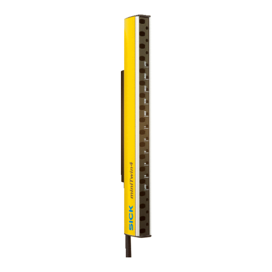
Twin-Stick Twin-Stick The miniTwin2 safety light curtain comprises two identical Twin Sticks of small size. Each Twin Stick contains both a sender unit and a receiver unit (Fig. 1). The two Twin Sticks are mounted such that sender unit and receiver unit are opposite each other. The housing shape makes mounting intuitive. -
Page 13: Operating Principle Safety Light Curtain
(EDM) to the multifunction connections. Prerequisites for the protective function of the miniTwin2 safety light curtain The miniTwin2 safety light curtain operates correctly as a protective device only if the following conditions are met: The control of the machine must be electrical. -
Page 14: Cascading
3.2.3 Cascading To provide effective presence detection a maximum of three miniTwin2 can be connected in series as “cascade”. The device connected to the control cabinet is the main sensor, called host. The subse- quent sensors are called guest 1 and guest 2. On the host you can configure the Reset and EDM functions. -
Page 15: Application Examples
Fig. 5: Hazardous area protection using a miniTwin2 safety light curtain (right) Fig. 6: Access protection using a miniTwin2 safety light curtain 8013482/YT85/2016-02-23 © SICK AG • Industrial Safety Systems • Germany • All rights reserved Subject to change without notice... -
Page 16: Status Indicators
(240 mm, 300 mm etc.) the LED displays are always in the middle of the protective field. These miniTwin2 have further bi-colour LEDs that are fitted every 60 mm above and below the status indicators. - Page 17 In connection with the ERR LED Red: Display of an error. Please refer to chapter 8 on page 62. Feedback on the deactivation of the configuration 8013482/YT85/2016-02-23 © SICK AG • Industrial Safety Systems • Germany • All rights reserved Subject to change without notice...
-
Page 18: Configurable Functions
Operating Instructions miniTwin2 Configurable functions This section describes the functions of the miniTwin2 safety light curtain that can be configured. Test the protective device after any changes! Changes to the configuration of the devices can degrade the protective function. After... -
Page 19: Reset
You can only implement a restart interlock via an external machine restart interlock: The miniTwin2 has no control over the restart. You can implement a reset using the Reset function on the miniTwin2: The miniTwin2 controls the machine start. Ensure on the usage of the Reset function that an erroneous start-up cannot result in a... - Page 20 It is imperative you configure the application with restart interlock if it is possible to stand behind the safety light curtain! The miniTwin2 is unable to verify if the restart interlock of the machine is operable. If in WARNING applications in which it is possible to stand behind the safety light curtain you deactivate both the internal Reset function and the external restart interlock, you will place the machine operator in acute danger.
-
Page 21: External Device Monitoring (Edm)
External device monitoring (EDM) The EDM checks if the contactors actually de-energize when the protective device responds. If you activate external device monitoring, then the miniTwin2 checks the contactors after each interruption to the light path and prior to the machine restart. The EDM can so identify if one of the contactors has welded, for instance. -
Page 22: Mounting
Operating Instructions miniTwin2 Mounting This chapter describes the preparation and completion of the mounting of the miniTwin2 safety light curtain. The mounting requires two steps: determining the necessary minimum distance mounting using the available brackets (see section “Safety light curtains” in the SICK product catalogue “Industrial Safety Systems”... -
Page 23: Yt85/2016
(the stopping/run-down time is shown in the machine documentation or must be determined by taking a measurement.) response time of the entire protective device, e.g. miniTwin2 consisting of host and guest (response times see 9.1 “Data sheet” on page 64) - Page 24 (inches) = 3.4 × (effective resolution – 0.276), but not less than 0. © SICK AG • Industrial Safety Systems • Germany • All rights reserved 8013482/YT85/2016-02-23 Subject to change without notice...
-
Page 25: Minimum Distance To Reflective Surfaces
[mm] = tan 5° × D [m] × 1000 Example: = tan 5° × 4 m × 1000 = 349.95 mm ~ 350 mm 8013482/YT85/2016-02-23 © SICK AG • Industrial Safety Systems • Germany • All rights reserved Subject to change without notice... -
Page 26: Minimum Distance For Cascaded Systems
[mm] = tan 10° × D [m] × 1000 Example: a = tan 10° × 4 m × 1000 a = 705.31 mm ~ 706 mm © SICK AG • Industrial Safety Systems • Germany • All rights reserved 8013482/YT85/2016-02-23 Subject to change without notice... -
Page 27: Steps For Mounting The Device
– Affix the information label “Important Information” to the system in close proximity to the miniTwin2. 8013482/YT85/2016-02-23 © SICK AG • Industrial Safety Systems • Germany • All rights reserved Subject to change without notice... -
Page 28: Mounting Direction Of The Twin Sticks
Twin-Stick Twin-Stick The miniTwin2 safety light curtain comprises two identical Twin Sticks of small size. Each Twin Stick contains both a sender unit and a receiver unit (Fig. 1). The two Twin Sticks are mounted such that sender unit and receiver unit are opposite each other. The housing shape makes mounting intuitive. -
Page 29: Mounting With Oafix Bracket
O@Fix bracket The OAFix bracket is mounted at the top and bottom of the miniTwin2 safety light curtain. The length of the related Twin Stick is increased by ca. 13 mm by the OAFix bracket (see dimensional drawing in section 9.3.2 on page 69). - Page 30 252.6 312.6 372.6 432.6 492.6 552.6 612.6 672.6 732.6 792.6 852.6 912.6 972.6 1020 1032.6 1080 1092.6 1140 1152.6 1200 1212.6 © SICK AG • Industrial Safety Systems • Germany • All rights reserved 8013482/YT85/2016-02-23 Subject to change without notice...
-
Page 31: Mounting With Cafix Bracket
Fig. 20: Application example for mounting with C@Fix bracket Fig. 21: C@Fix bracket Washer Fixing screw M5 Part No. 2045843 8013482/YT85/2016-02-23 © SICK AG • Industrial Safety Systems • Germany • All rights reserved Subject to change without notice... - Page 32 Fasten the M3 screws for the CAFix brackets to a torque of approx. 1.5 Nm to fix the Twin Stick ( ). © SICK AG • Industrial Safety Systems • Germany • All rights reserved 8013482/YT85/2016-02-23 Subject to change without notice...
-
Page 33: Mounting With Lafix Bracket
Chapter 4 miniTwin2 4.2.5 Mounting with LCFix bracket Mount the 120 mm miniTwin2 with the aid of two LAFix brackets. Mounting with two LAFix brackets is only allowed up to a size of 540 mm. Note Fig. 23: L@Fix bracket Washers 1. - Page 34 Fasten the screws for the LAFix bracket ( ) to a torque of approx. 1.5 Nm, to obtain an adequate bracket clamping force. Fig. 24: Mounting of the miniTwin2 with L@Fix bracket © SICK AG • Industrial Safety Systems • Germany • All rights reserved 8013482/YT85/2016-02-23 Subject to change without notice...
-
Page 35: Mounting With Cafix Bracket And Lafix Bracket
C@Fix and L@Fix bracket Fig. 26: L@Fix bracket Washers 1. Fixing screw M5 2. Fixing screw M5 Part No. 2045843 8013482/YT85/2016-02-23 © SICK AG • Industrial Safety Systems • Germany • All rights reserved Subject to change without notice... - Page 36 Fasten the M3 screws for the CAFix bracket to a torque of approx. 1.5 Nm to fix the Twin Stick ( ). © SICK AG • Industrial Safety Systems • Germany • All rights reserved 8013482/YT85/2016-02-23 Subject to change without notice...
-
Page 37: Mounting With Cafix-Flex Bracket
Fasten the M5 fixing screws of both C-Fix-Flex brackets to a torque of approx. 5 Nm. Higher torques can damage the bracket; lower torques provide inadequate protection against vibration ( ). 8013482/YT85/2016-02-23 © SICK AG • Industrial Safety Systems • Germany • All rights reserved Subject to change without notice... - Page 38 Operating Instructions miniTwin2 Fig. 29: Mounting using C@Fix@Flex bracket, protective field parallel to the mounting surface 4° 20.6 Across flats 3 mm © SICK AG • Industrial Safety Systems • Germany • All rights reserved 8013482/YT85/2016-02-23 Subject to change without notice...
- Page 39 Fig. 30: Mounting using C@Fix@Flex bracket, protective field perpendicular to the mounting surface 20.4 Min. 29 Across flats 3 mm 8013482/YT85/2016-02-23 © SICK AG • Industrial Safety Systems • Germany • All rights reserved Subject to change without notice...
-
Page 40: Resolution At The End Of The Twin Sticks
Twin Stick (mm) Example: Twin-Sticks with 14 mm resolution C-Fix bracket/ C-Fix-Flex bracket O-Fix bracket L-Fix bracket © SICK AG • Industrial Safety Systems • Germany • All rights reserved 8013482/YT85/2016-02-23 Subject to change without notice... -
Page 41: Electrical Installation
0 V connections for the loads and the related protective device. 8013482/YT85/2016-02-23 © SICK AG • Industrial Safety Systems • Germany • All rights reserved Subject to change without notice... - Page 42 The device connection and the extension connection (see Fig. 32 or Fig. 35) are only allowed to be connected when the device is electrically isolated. © SICK AG • Industrial Safety Systems • Germany • All rights reserved 8013482/YT85/2016-02-23 Subject to change without notice...
-
Page 43: System Connection
Chapter 5 miniTwin2 System connection The miniTwin2 safety light curtain is connected using a system plug on the device connection. For standalone devices a system plug with a system connection is available. Fig. 32: Device connection and system plug with system... -
Page 44: Pin Assignment System Connection
Pre-assembled cables with flying leads are available for the connection to your application (see section 10.6 “Accessories” on page 77). © SICK AG • Industrial Safety Systems • Germany • All rights reserved 8013482/YT85/2016-02-23 Subject to change without notice... -
Page 45: Cascading
Cascading A maximum of three miniTwin2 can be connected in series as “cascade”. For cascaded systems a system plug with a system connection M12 × 4 + FE (male connector) and an extension connection M12 × 4 + FE (female connector) is available. -
Page 46: Changes To Cascaded Systems
Check the effectiveness of the protective device as described in section 6.7 “Test notes” WARNING on page 56. © SICK AG • Industrial Safety Systems • Germany • All rights reserved 8013482/YT85/2016-02-23 Subject to change without notice... -
Page 47: Protective Operation Without Reset And/Or Without Edm
Chapter 5 miniTwin2 Protective operation without Reset and/or without If you configure the miniTwin2 safety light curtain in protective operation without Reset and/or without EDM, you must connect the related multifunction connection or both multifunction connections to 0 V. Fig. 37: Connection of the... -
Page 48: Reset Button
If you connect the reset button, then you must configure the function manually during commissioning (see section 6.5 “Configuration of the Reset function” on page 55). © SICK AG • Industrial Safety Systems • Germany • All rights reserved 8013482/YT85/2016-02-23... -
Page 49: External Device Monitoring (Edm)
“Configuration of the external device monitoring (EDM)” on page 56). You must connect the contacts to be monitored together on the external device monitoring input (EDM) on a miniTwin2. 8013482/YT85/2016-02-23 © SICK AG • Industrial Safety Systems • Germany • All rights reserved Subject to change without notice... -
Page 50: Connection Diagrams
Chapter 5 Operating Instructions miniTwin2 Connection diagrams Fig. 40: miniTwin2 in connection with UE10@2FG Fig. 41: miniTwin2 in connection with UE10@3OS © SICK AG • Industrial Safety Systems • Germany • All rights reserved 8013482/YT85/2016-02-23 Subject to change without notice... - Page 51 Operating Instructions Chapter 5 miniTwin2 Fig. 42: miniTwin2 with Flexi Classic safety controller Fig. 43: miniTwin2 with Flexi Soft safety controller 8013482/YT85/2016-02-23 © SICK AG • Industrial Safety Systems • Germany • All rights reserved Subject to change without notice...
-
Page 52: Sick Ag • Industrial Safety Systems • Germany • All Rights Reserved 8013482/Yt85/2016-02-23
Commissioning and configuration Commissioning requires a thorough check by qualified safety personnel! Before you operate a system protected by the miniTwin2 safety light curtain for the first time, make sure that the system is first checked and released by qualified safety WARNING personnel. -
Page 53: Alignment Of The Safety Light Curtain
The light beams emitted by the sender optics must hit the receiver optics accurately. The miniTwin2 safety light curtain signals the alignment quality with the aid of the blue LEDs (1 to 5), i.e. how well the two Twin Sticks are aligned with each other. If all LEDs illuminate, the alignment is optimal, if no LED illuminates, the alignment is poor. - Page 54 During all further power up processes, the LED only flashes if the previous system partner does not reply within 20 seconds. In this case the communication can also be established with a replacement stick. © SICK AG • Industrial Safety Systems • Germany • All rights reserved 8013482/YT85/2016-02-23...
-
Page 55: Default Delivery Status
(lockAout). Configuration of the Reset function To activate the Reset function, a reset button must be connected to the miniTwin2 safety light curtain (see section 5.4 on page 48). You have 4 minutes to configure the function after switching on the safety light curtain. -
Page 56: Configuration Of The External Device Monitoring (Edm)
© SICK AG • Industrial Safety Systems • Germany • All rights reserved 8013482/YT85/2016-02-23 Subject to change without notice... -
Page 57: Daily Functional Checks Of The Protective Device
Fig. 45. This procedure allows you to test if the presence detection/reaching behind protection is functioning correctly (see 4.2 “Steps for mounting the device” on page 27). During all thorough checks on the miniTwin2 only the OUT LED is allowed to illuminate red Note and the orange RES LED must never flash. -
Page 58: Deactivating Reset And Edm
At least three of the five LEDs must be illuminated for you to be able to deactivate the configuration. Switch off and on again the safety light curtain and start with the deactivation within 2 minutes. © SICK AG • Industrial Safety Systems • Germany • All rights reserved 8013482/YT85/2016-02-23 Subject to change without notice... - Page 59 Keep the safety light curtain’s protective field clear until the COM LED flashes White 1× (after approx. 3 s). 8013482/YT85/2016-02-23 © SICK AG • Industrial Safety Systems • Germany • All rights reserved Subject to change without notice...
- Page 60 If the COM LED flashes White 2× in succession during deactivation, the procedure has Note been interrupted. In this case, repeat the complete procedure. © SICK AG • Industrial Safety Systems • Germany • All rights reserved 8013482/YT85/2016-02-23 Subject to change without notice...
-
Page 61: Care And Maintenance
Use a clean and soft brush to remove dust from the front screen. Now wipe the front screen with a clean and damp cloth. After cleaning, check the position of the miniTwin2 to ensure that the protective device Note cannot be bypassed (reaching over, under or standing behind). -
Page 62: Fault Diagnosis
Rectify the cause of the fault as per Tab. 10. Switch off and on again the voltage supply for the miniTwin2 in the control cabinet or remove and re-fit the system connection (M12 × 4 + FE) on both Twin Sticks. - Page 63 Press the connected reset button (see 6.5 on page 55). Check the cabling of pin 2 (see 5.3 on page 47). 8013482/YT85/2016-02-23 © SICK AG • Industrial Safety Systems • Germany • All rights reserved Subject to change without notice...
-
Page 64: Technical Specifications
(SELV) must be able to bridge a brief mains failure of 20 ms. The power supply must provide safe mains isolation (SELV/PELV) and have a current limit of max. 8 A. Power supplies according to EN 60 204A1 satisfy this requirement. Suitable power supplies are available as accessories from SICK (see section 10.6 “Accessories” on page 77). - Page 65 Maximum power consumption of a system with 1200 mm protective field height and a resolution of 14 mm. 8013482/YT85/2016-02-23 © SICK AG • Industrial Safety Systems • Germany • All rights reserved Subject to change without notice...
- Page 66 Glass-fibre reinforced epoxy resin with flame retarding agent TBBPA System connection Cable sheath material TPU (PUR) Packaging Corrugated cardboard with polyethylene As per IEC 61 131A2. © SICK AG • Industrial Safety Systems • Germany • All rights reserved 8013482/YT85/2016-02-23 Subject to change without notice...
-
Page 67: Weight Tables
PNS75 and PNS125 PNS75 PNS125 1035 1580 1435 2190 1850 2820 2270 3450 2680 4080 3095 4710 1090 3510 5345 1240 8013482/YT85/2016-02-23 © SICK AG • Industrial Safety Systems • Germany • All rights reserved Subject to change without notice... -
Page 68: Dimensional Drawings
The protective field height S is the same as the size of the safety light curtain (see Tab. 16, Note Tab. 17and Tab. 18 from page 73). © SICK AG • Industrial Safety Systems • Germany • All rights reserved 8013482/YT85/2016-02-23 Subject to change without notice... -
Page 69: Oafix Bracket
LCFix bracket, C-Fix bracket (set) Fig. 49: Dimensional drawing 21.6 L@Fix bracket, C@Fix bracket (mm) Ca. 21 L@Fix bracket C@Fix bracket Part No. 2045843 (set) 8013482/YT85/2016-02-23 © SICK AG • Industrial Safety Systems • Germany • All rights reserved Subject to change without notice... -
Page 70: C-Fix-Flex Bracket (Pivoting)
Chapter 9 Operating Instructions miniTwin2 9.3.4 C-Fix-Flex bracket (pivoting) Fig. 50: Dimensional drawing C-Fix-Flex bracket, pivoting (mm) Approx. 40.5 Part No. 2056598 © SICK AG • Industrial Safety Systems • Germany • All rights reserved 8013482/YT85/2016-02-23 Subject to change without notice... -
Page 71: Deflector Mirror Pns75
The protective function of the system will be affected and the system will thus become unsafe. This would mean that the operator is at risk. 8013482/YT85/2016-02-23 © SICK AG • Industrial Safety Systems • Germany • All rights reserved Subject to change without notice... -
Page 72: Deflector Mirror Pns125
The protective function of the system will be affected and the system will thus become unsafe. This would mean that the operator is at risk. © SICK AG • Industrial Safety Systems • Germany • All rights reserved 8013482/YT85/2016-02-23... -
Page 73: Ordering Information
1207819 1207844 1207863 1080 (C2MT-10814BBC03FE0) (C2MT-10824BBC03FE0) (C2MT-10834BBC03FE0) 1207820 1207845 1207864 1140 (C2MT-11414BBC03FE0) (C2MT-11424BBC03FE0) (C2MT-11434BBC03FE0) 1207821 1207846 1207865 1200 (C2MT-12014BBC03FE0) (C2MT-12024BBC03FE0) (C2MT-12034BBC03FE0) 8013482/YT85/2016-02-23 © SICK AG • Industrial Safety Systems • Germany • All rights reserved Subject to change without notice... -
Page 74: 10.2 Minitwin2: Cascade Devices
1207882 1207901 1207920 1080 (C2MT-10814BBC04FE0) (C2MT-10824BBC04FE0) (C2MT-10834BBC04FE0) 1207883 1207902 1207921 1140 (C2MT-11414BBC04FE0) (C2MT-11424BBC04FE0) (C2MT-11434BBC04FE0) 1207884 1207903 1207922 1200 (C2MT-12014BBC04FE0) (C2MT-12024BBC04FE0) (C2MT-12034BBC04FE0) © SICK AG • Industrial Safety Systems • Germany • All rights reserved 8013482/YT85/2016-02-23 Subject to change without notice... -
Page 75: Minitwin2: Standalone Devices With Oafix Bracket
1207939 1207958 1207977 1080 (C2MT-10814BBC03FB0) (C2MT-10824BBC03FB0) (C2MT-10834BBC03FB0) 1207940 1207959 1207978 1140 (C2MT-11414BBC03FB0) (C2MT-11424BBC03FB0) (C2MT-11434BBC03FB0) 1207941 1207960 1207979 1200 (C2MT-12014BBC03FB0) (C2MT-12024BBC03FB0) (C2MT-12034BBC03FB0) 8013482/YT85/2016-02-23 © SICK AG • Industrial Safety Systems • Germany • All rights reserved Subject to change without notice... -
Page 76: Additional Front Screen (Weld Spark Guard)
Do not use deflector mirrors if the formation of droplets or heavy contamination of the deflector mirrors is to be expected! WARNING © SICK AG • Industrial Safety Systems • Germany • All rights reserved 8013482/YT85/2016-02-23 Subject to change without notice... -
Page 77: 10.6 Accessories
From devices with a size of 360 mm we recommend the usage of an additional C-Fix bracket near the L-Fix bracket. 8013482/YT85/2016-02-23 © SICK AG • Industrial Safety Systems • Germany • All rights reserved Subject to change without notice... -
Page 78: Annex
Complete EU declaration of conformity for download: www.sick.com © SICK AG • Industrial Safety Systems • Germany • All rights reserved 8013482/YT85/2016-02-23 Subject to change without notice... -
Page 79: 11.2 Checklist For The Manufacturer
18. Has an information label for the daily check been attached so that it is easily visible for the operator? This checklist does not replace the initial commissioning, nor the regular inspection by qualified safety personnel. 8013482/YT85/2016-02-23 © SICK AG • Industrial Safety Systems • Germany • All rights reserved Subject to change without notice... -
Page 80: 11.3 List Of Tables
Tab. 19: Part numbers additional front screen (weld spark guard)........76 Tab. 20: Part numbers deflector mirrors PNS75 and PNS125........... 76 Tab. 21: Part numbers accessories ..................77 © SICK AG • Industrial Safety Systems • Germany • All rights reserved 8013482/YT85/2016-02-23 Subject to change without notice... -
Page 81: 11.4 List Of Illustrations
Mounting the system plug on a cascaded system ..........46 Fig. 37: Connection of the multifunction connections in protective operation without Reset and without EDM ................47 8013482/YT85/2016-02-23 © SICK AG • Industrial Safety Systems • Germany • All rights reserved Subject to change without notice... - Page 82 Dimensional drawing C-Fix-Flex bracket, pivoting (mm) ........70 Fig. 51: Dimensional drawing deflector mirror PNS75 (mm)..........71 Fig. 52: Dimensional drawing deflector mirror PNS125 (mm)........... 72 © SICK AG • Industrial Safety Systems • Germany • All rights reserved 8013482/YT85/2016-02-23 Subject to change without notice...
- Page 83 Annex Operating Instructions Chapter 11 miniTwin2 8013482/YT85/2016-02-23 © SICK AG • Industrial Safety Systems • Germany • All rights reserved Subject to change without notice...
- Page 84 Phone +386 (0)1-47 69 990 E-Mail ghk@sick.com.hk E-Mail office@sick.si Hungary South Africa Phone +36 1 371 2680 Phone +27 11 472 3733 More representatives and agencies E-Mail office@sick.hu E-Mail info@sickautomation.co.za at www.sick.com SICK AG | Waldkirch | Germany | www.sick.com...
Need help?
Do you have a question about the miniTwin2 and is the answer not in the manual?
Questions and answers