Advertisement
Quick Links
Advertisement

Related Manuals for Casall Inifinity Hybrid


Summary of Contents for Casall Inifinity Hybrid
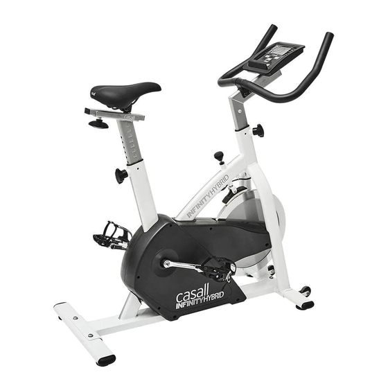
- Page 1 Assembly & Operating Instructions For Inifinity Hybrid...
-
Page 2: Serial Number
Important: Please locate your serial number and record in the box below for service support purposes. Serial number Serial number here:... - Page 3 INIFINITY HYBRID N-1 Flat Washer Ø8*Ø19*2t N-2 Allen Bolt M8*P1.25*12mm (4) N-3 Allen Bolt M8*P1.25*20mm (4) Box Spanner(1) Allen Key(1) Screwdriver (1) (MM)
- Page 4 EXPLORATION DRAWING E-13 M-10 E-28 H-2 H-3 E-12 E-11 E-10 E-30 E-22 D-4 D-5 E-19 N-4R E-15 E-16 E-17 E-18 E-20 E-34 E-27 E-26 E-25 K-1 K-2 K-8 K-9 E-23 E-11 N-4L E-33 E-29 K-6 K-7 E-31 J-4 J-5 E-14 E-21...
-
Page 5: Complete Bike Assembly
COMPLETE BIKE ASSEMBLY N-4R N-4L... -
Page 6: Parts List
PARTS LIST PART NO. DESCRIPTION A, A-1 Computer and Screw Handlebar Foam grip for handlebar 2PCS Cap for handlebar 2PCS Handlebar post End cap of handlebar post Screw M3*14 Stopper for handlebar Screw M5*12 Upper cap for handlebar post Upper cable for computer Rear stabilizer End cap for rear stabilizer 2PCS... - Page 7 E-11 Screw M5x14L 4PCS E-12 Bushing for chain cover E-13 Belts 1320m/m E-14 Belts 813m/m E-15 Bearing 6004RS 2PCS E-16 Nut M20*P1.0 Flat washerφ20.3xφ30x1t E-17 E-18 Sensor holder E-19 Sensor box E-20 Screw M4x10L for sensor holder E-21 DC cable E-22 Cap for hand post holder E-23,E-28...
- Page 8 Pressing spring for Brake U holder for Brake Brake piece for Brake Bushing φ9x18L for Brake Flat washerφ10xφ14x1t for Brake 2PCS M-10 Screw M5x8 for Brake 2PCS N-1~N-3 Bolts & nuts pack 1SET Pedal 1SET Seat Adaptor...
- Page 9 STEP 1 1. Attach the front stabilizer (D) to the main frame (E) using two flat washer (N-1) and allen bolt (N-3). 2. Attach the rear stabilizer (C) to the main frame (E) using two flat washer (N-1) and allen bolt (N-3) After assembly, the Trainer can be adjusted to slightly uneven ground by adjusting the height of the foot caps at the front and back.
- Page 10 STEP 2 1. Assemble the left pedal (N-4L) to the left crank (E-29) and the right pedal (N-4R) to right crank (E-30). 2. Assemble the seat (N-5) to the seat post (L). 3. Then choose the desired position and tighten the knob (E-1). Be sure the knob is always tightened.
- Page 11 STEP 3 3.1 : Please remove the adjusting knob (E-2) from the main frame (E). 3.2 : Release the screw from the lower sleeve and take of the sleeve from the handlebar post but do not take the sleeve off the lower cable. 3.3 : Insert the handlebar post (B-3) into the main frame (E), then choose the desired position and tighten the adjusting knob (E-2).
- Page 12 STEP 4 1. Connect the upper cables (B-9) then attach the computer (A) to the computer bracket with the enclosed Screws (A-1) 2. Connect the adaptor (N-6) to the DC hole (located on the back of the chain cover). Screwdriver (1)
- Page 13 SM3728-64 INSTRUCTIONAL MANUAL !!! For simple exercise, it is not always necessary to select a training program or manually set the TIME, DISTANCE or other values. You can simply start pedaling.
- Page 14 As soon as the computer is connected with power supply, an acoustic signal sounds and all of the displays are shown on LCD for 2 seconds, then showing wheel diameter. If no button are pressed and the pedals have not been moved for approx. 4 minutes, the computer will switch to power saving mode.
- Page 15 2 shot beeps =It is impossible to make any settings Training Data The computer calculates and displays all values automatically according to user exercising status (see table). Take note: * If only a “P” is shown instead of pulse value, it is impossible to measure the HR. Wear the chest belt properly so that computer can detect your hear rate.
- Page 16 Selecting a Program to do training (PROGRAM) -Press UP and DOWN keys to scan MANUAL→PROGRAM USER PROGRAM HRC WATT. -Choose PROGRAM and press MODE to confirm. The programs are preset with 12 profiles. Press UP and DOWN to select one from the 12 preset profiles. Set the desired session value and confirm by MODE: .
- Page 17 -During the program profile setting, user may press MODE to finish or holding it for 2s to quit setting. -You can adjust the level of resistance on the paddles while exercising by pressing UP and DOWN keys. The newly set level value will be shown in the profile(default value is Level 1). -As soon as one of the set values reach the preset Target, the computer will alarm with Bi-bi sound and stop.
- Page 18 -Press STATR/STOP to start workout. -For this program, it is necessary to wear the chest belt so that computer can detect and display your heart rate value. -Program sequence: The computer sets a paddle resistance that keeps you exercising constantly within your target pulse rate.
- Page 19 -If your heart rate is still very high after 60s (F is between 4 and 6), you could restart the recovery program to gradually slow your heart rate further. Trouble shooting: E-2 : Motor stroke over the normal range. Plug the adaptor again. Re-power on the console and the motor will back to the normal range.
Need help?
Do you have a question about the Inifinity Hybrid and is the answer not in the manual?
Questions and answers