
Related Manuals for WaterLogic infiniti


Summary of Contents for WaterLogic infiniti
- Page 1 OPERATING, INSTALLATION, AND SERVICE MANUAL Waterlogic 77 McCullough Drive – Suite 9 New Castle, DE 19720 (888) 826-6597 Tech Portal Website: www.techportal.waterlogic.com...
-
Page 2: Table Of Contents
Waterlogic infiniti OPERATING, INSTALLATION, AND SERVICE MANUAL Congratulations on your choice of the Waterlogic infiniti Water Treatment System, water treatment system. The infiniti Water Treatment System, model dispenses cold, and hot. Every infiniti Water Treatment System, includes: Bio-Cote Anti-Microbial Protection... -
Page 3: Features And Benefits
Leak Detection infiniti Water Treatment Systems are supplied with a Sensor in the Leak Tray that halts water supply to prevent overflow and sounds alarm to reduce accident potential. Energy Saving Sleep Mode Energy saving Sleep Mode can be programmed to turn off heater after 3 hours of inactivity. -
Page 4: Certifications
Intertek Labs (ETL) Certified the infiniti Water Treatment System, to ANSI/UL 399 Standard for Drinking Water Coolers. BPA Free - Waterlogic tests for BPA and declares that all of its products are Bisphenol-A FREE and contain no harmful BPA plastics. -
Page 5: Introduction And Safety Alert Symbols
INTRODUCTION Carefully read and follow all instructions to ensure proper and efficient operation of your infiniti Water Treatment System. Contact Waterlogic or an Authorized Waterlogic Dealer if you have any questions. Waterlogic and Authorized Waterlogic Dealers employ trained service personnel who are experienced in the installation, function and repair of Waterlogic equipment. -
Page 6: Safety Precautions
Dispenser Could Tip or Fall causing serious injury. Always install unit on a firm, flat, and level surface and secure the infiniti Water Treatment System, to the base cabinet with the screw provided to lock the components together. Never place heavy items on top of unit and never climb, stand, or hang on unit or storage cabinet to prevent injury and damage. -
Page 7: Model And Part Designations
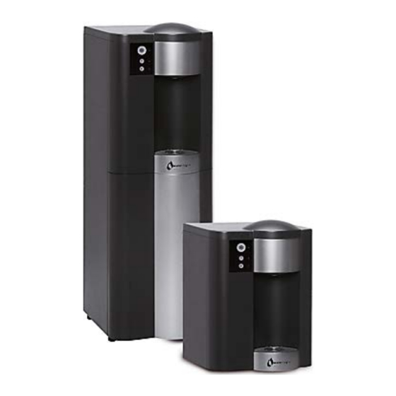
1.8 Amps infiniti TOTAL 1016 8.4 Amps #infiniti Counter Top is 19 inches. tall and may not fit between countertops and cabinets - Check installation to ensure adequate clearance. infiniti Operating, Installation, and Service Manual Page 7 - Revision: 9-15-2016... -
Page 8: Operating Instructions
OPERATING INSTRUCTIONS The above picture shows front LED and control panel for the Waterlogic infiniti Water Treatment System, water treatment systems. Button Operational Use Cold Water - Press Dispensing Button to start dispensing cold water until desired fill. Cold Water is the Default Water Selection Hot Water –... -
Page 9: Hot Tank Principles Of Operation
HOT TANK PRINCIPLES OF OPERATION All Waterlogic Hot Tanks have a built in Vent or Expansion Chamber in the top of the tank except for WL270 (GF) units. The Vent Chamber allows for expansion of the water when it is heated. -
Page 10: Flow Diagram
Waterlogic infiniti Water Treatment System, WATER FLOW DIAGRAM Water In Solenoid Valve Condenser Cold Tank Filter Dryer Compressor infiniti Operating, Installation, and Service Manual Page 10 - Revision: 9-15-2016... -
Page 11: Programming - Disabling Sleep Mode
PROGRAMMING INSTRUCTIONS CHANGING ENERGY SAVER MODE TO NON ENERGY SAVING MODE Infiniti UV Water Treatment System comes programmed to Energy Saver Mode. To turn off the Energy Saving Mode, move the Jumper on CH6 from Pins 1-2 to Pins 2-3 Display PCB –... -
Page 12: Pre-Installation Procedures
CAUTION! FILTER FLUSH REQUIRED. infiniti Water Treatment Systems, are not supplied with filters. Filters should be configured to optimize your system. Filters need to be configured and specified to do the job given the local water conditions, usage, maintenance schedule, and placement restrictions. - Page 13 13. Again isolate the water to the water cooler and release any internal water pressure. 14. Isolate the electrical power. 15. If this procedure is being done in conjunction with the annual service, change the filters. infiniti Operating, Installation, and Service Manual Page 13 - Revision: 9-15-2016...
- Page 14 75°F (24°C) to the factory set point of 185°F (85°C). Dispense a cup of hot water to ensure the temperature/odor/taste is acceptable. WARNING! VERY HOT WATER CAN BURN OR SCALD. Hot water should be dispensed carefully into insulated container to avoid injury. infiniti Operating, Installation, and Service Manual Page 14 - Revision: 9-15-2016...
-
Page 15: Draining Procedures
Drain the Cold Water Tank and Circuit 3. Remove the Front Cover. 4. Remove the Faucet, and move the Front Cover to the top of the infiniti Water Treatment System to gain access to the draining tubes 5. Remove tubing from JG fittings, and allow water to drain into drains, catch basin, etc. - Page 16 Turn off Water Supply and Bleed Water Pressure 1. Isolate the infiniti Water Treatment System from feed water by turning off the supply. 2. Dispense cold still water to relieve any pressure built up in the system.
- Page 17 7. Reconnect tubing into inlet elbows once drained, and reinstall the filter head bracket. 8. Dry inside of unit if necessary. 9. Replace lower front panel. infiniti Operating, Installation, and Service Manual Page 17 - Revision: 9-15-2016...
-
Page 18: Installation Procedures
Pre-installation and sanitization procedures as prescribed in this manual must be performed before installing the infiniti Water Treatment System, Always install indoors and place the Waterlogic infiniti Water Treatment System, on a firm, flat and stable surface. infiniti Operating, Installation, and Service Manual... - Page 19 NOTE: Switches have internal LED that illuminates when placed in I=ON position. 3. Connect the power cord to the back of the Waterlogic infiniti Water Treatment System, and to a 120 Volt supply. 4. Fill the Cold Tank. Hold a container under the dispensing faucet, press and hold the main dispensing button until a continuous flow of water is obtained.
-
Page 20: Cold Water Setting
Do not adjust past the “Max Cold” position at 3:00 position to avoid freezing the cold tank. Turning the adjustment screw counter-clockwise to raise the set point temperature. infiniti Operating, Installation, and Service Manual Page 20 - Revision: 9-15-2016... -
Page 21: Replacement Components
1.6 Liter Capacity WLCP PN 10-4029 Replacement parts can be obtained from Waterlogic Dealer. See Parts Layout Drawing and Parts List for additional repair parts. Hot Tank Service Hot Tanks (with controls) must be replaced at least every 3-5 years depending on usage. -
Page 22: Hot Tank Descaling Instructions
(colored water) comes out of the faucet. Container and drain basic will be required to catch water from the faucet. 4. Turn off water supply and remove sanitizing cartridge from inlet water supply. Reconnect water supply to inlet fitting. infiniti Operating, Installation, and Service Manual Page 22 - Revision: 9-15-2016... - Page 23 5. Allow descaling solution to remain in the Hot Tank for 15 minutes (length of time may vary depending on water conditions). 6. Place a pitcher, catch basin or other container under the faucet of the infiniti Water Treatment System, 7.
-
Page 24: Resetting The Overload Or High Limit Safety
Hot Tank to the upper base of the WL100 Water Treatment System unit and lower the Hot Tank so you can remove the Protective Metal Box. infiniti Operating, Installation, and Service Manual Page 24 - Revision: 9-15-2016... - Page 25 The Hot and Cold tanks must be filled with water BEFORE turning on the Red Heater and Compressor Switch. Verify the cooler is fully operational before installing it at the customers’ site. infiniti Operating, Installation, and Service Manual Page 25 - Revision: 9-15-2016...
-
Page 26: Parts Drawings And Parts Lists
Waterlogic infiniti PARTS DRAWING AND PARTS LIST Wetted Parts infiniti Operating, Installation, and Service Manual Page 26 - Revision: 9-15-2016... - Page 27 Waterlogic infiniti PARTS DRAWING AND PARTS LIST Part No Description Side Panel – Charcoal ST-8236 Counter Top Only Side Panel – Charcoal ST-8153 Tower Only Bulkhead Union ¼” x ¼” John Guest P/N PU-4028-A PI1208S Stem Elbow Connector ¼” * ¼” – Acetyl (John...
- Page 28 12.3 PL-1088 Faucet - Stainless Steel Insert Filter Bracket – Assembled to ST-8134 ST-8248 Tower Only Omnipure Non-Valved Head(Q NON VALVED PU-4075 HEAD JJ) PU-4016 Solenoid Valve DC24V 1000mm infiniti Operating, Installation, and Service Manual Page 28 - Revision: 9-15-2016...
- Page 29 ST-8235 Counter Top Only Bottom Shelf ST-8137 Tower Only Leak Tray PL-0116-L00-00 Counter Top Only 19.1 Leak Tray PL-1294-A Tower Only Leak Sensor Wire 19.2 EL-5076-KR Counter Top Only infiniti Operating, Installation, and Service Manual Page 29 - Revision: 9-15-2016...
- Page 30 20.1 ST-0080-L00-00 Under Top Cover Counter Top Only EN-0010-L00-00 Relay PCB EL-5003-A Power Transformer Upper Shelf ST-8234 Countertop Only ST-8136-R2 Upper Shelf – Tower Only HT-3024 Hot Tank 1.6L infiniti Operating, Installation, and Service Manual Page 30 - Revision: 9-15-2016...
- Page 31 Power Line Noise Filter, ElectroMagnetic EL-5016 Interference Filter (EMI) Fuse Holder and Fuse ( 120V / 15A) with One EL-5053 Wire 28.1 EL-5010 Fuse 120V / 15A EL-5004 Red Power – Heater Switch infiniti Operating, Installation, and Service Manual Page 31 - Revision: 9-15-2016...
- Page 32 LPDE Blue Tube ¼” (John Guest PN PE-08-BI- PU-4031-A 1000F-B) PU-4064 Silicon Tube for Hot Water 5/16” EN-6059 Plastic PCB Support shown EL-5001-A Power Cord 120V – 1825 mm Shown infiniti Operating, Installation, and Service Manual Page 32 - Revision: 9-15-2016...
-
Page 33: Electrical Diagram
ELECTRICAL DIAGRAM DANGER! HIGH VOLTAGE ELECTRICAL HAZARD. PCB (Printed Circuit Board) contains High Voltage. Only trained and qualified technicians should attempt live testing. infiniti Operating, Installation, and Service Manual Page 33 - Revision: 9-15-2016... - Page 34 Water is in the bottom of the unit. Open up unit to determine where the Leak in infiniti Water leak is. Treatment System, Check for source of leak. Dry out inside of unit. infiniti Operating, Installation, and Service Manual Page 34 - Revision: 9-15-2016...
- Page 35 Wait for cold tank to chill water to temperature prior to dispensing more cold water. Cold tank capacity is 4 liters for Tower and 2 liters for Counter A greater capacity of Waterlogic Water Systems is available. Top. Check continuity of thermostat with multimeter. Replace Cold Water Thermostat thermostat as required.
-
Page 36: Troubleshooting
Thermostat and Overload separately. Thermostat or overload Good components will indicate a closed circuit or zero “open” on Hot Tank OHM’s on the meter. Replace components as necessary. infiniti Operating, Installation, and Service Manual Page 36 - Revision: 9-15-2016... - Page 37 Turn Power off; Drain hot tank; Use multi-meter to check heater element for approximately 26 OHM’s resistance. Heating Coil not Working Hot tank must be empty if you are checking for continuity. Replace Hot Tank as necessary. infiniti Operating, Installation, and Service Manual Page 37 - Revision: 9-15-2016...
- Page 38 Hot Tank to the upper base of the WL100 Water Treatment System unit and lower the Hot Tank so you can remove the Protective Metal Box. infiniti Operating, Installation, and Service Manual Page 38 - Revision: 9-15-2016...
- Page 39 The Hot and Cold tanks must be filled with water BEFORE turning on the Red Heater and Compressor Switch. Verify the cooler is fully operational before installing it at the customers’ site. infiniti Operating, Installation, and Service Manual Page 39 - Revision: 9-15-2016...
- Page 40 Failed Power Line Noise Filter, ElectroMagnetic Interference Replace EMI filter (EMI) Defective Red Heater and Replace Red Heater and Power Power Switch infiniti Operating, Installation, and Service Manual Page 40 - Revision: 9-15-2016...
- Page 41 Make sure unit is not under minimum ventilation requirements (2 Reduction of airflow into unit. to 4 inches). Compressor is running very Low or lost refrigerant. Refrigerant recharge required. hot. infiniti Operating, Installation, and Service Manual Page 41 - Revision: 9-15-2016...
- Page 42 Compressor Starting Circuit Inspect the starter and overload relay for any defects. Replace components(s) as needed. Turn Red Heater and Power Switch on I = ON and retest compressor operation. infiniti Operating, Installation, and Service Manual Page 42 - Revision: 9-15-2016...
- Page 43 11. Small amount of water periodically dispenses from faucet automatically 12. Dispense Buttons Stick 13. Run-On - Water continues to dispense out of faucet after releasing the dispense button • Also includes related instruction for Hot Tank Descaling. infiniti Operating, Installation, and Service Manual Page 43 - Revision: 9-15-2016...
- Page 44 Dirt or Foreign material is filling the gap around the push-buttons. Dispensing Button Stuck Inspect the push buttons and clean surrounding area. Inspect faucet assembly inside the unit and clean as necessary. infiniti Operating, Installation, and Service Manual Page 44 - Revision: 9-15-2016...
- Page 45 See Hot Tank Descaling Instructions that are included further Hot Tank outlet hole is scaled below in this Troubleshooting Section. over. See instructional video on the Partner Area of the Waterlogic.com website for more information. Expansion chamber is not Replace the Hot Tank.
- Page 46 Remove the PCB to inspect the front of the board. Inspect valve components for proper function. Replace as Solenoid Valve is Malfunctioning necessary. infiniti Operating, Installation, and Service Manual Page 46 - Revision: 9-15-2016...
- Page 47 See instructional video on the Partner Area of the Waterlogic.com website for more information. All Waterlogic Hot Tanks have a built in Vent or Expansion Chamber in the top of the tank except for WL270 (GF) units. The Vent Chamber allows for expansion of the water when it is heated.
- Page 48 Display PCB. Verify the soldering points on Loose connection(s) on the connections are secure into the board. Display PCB Remove the PCB to inspect the front of the board. Exhausted Filter Replace filters as needed. infiniti Operating, Installation, and Service Manual Page 48 - Revision: 9-15-2016...
- Page 49 Remove cold water outlet tube from tank to faucet. Pour some tank outlet tube. scale remover into cold tank. Expansion chamber in Cold Replace Cold Tank. Tank is not sealed properly. infiniti Operating, Installation, and Service Manual Page 49 - Revision: 9-15-2016...
- Page 50 Dirt or Foreign material is Inspect the push buttons and clean surrounding area. Inspect filling the gap around the faucet assembly inside the unit and clean as necessary. push-buttons. infiniti Operating, Installation, and Service Manual Page 50 - Revision: 9-15-2016...
- Page 51 Reason “Run On” or “Carry On” is present in all Waterlogic pressure fed units without outlet solenoids. “Run On” is defined is the amount of water that continues to dispense out of the faucet after releasing the dispense button.
- Page 52 (colored water) comes out of the faucet. Container and drain basic will be required to catch water from the faucet. 12. Turn off water supply and remove sanitizing cartridge from inlet water supply. Reconnect water supply to inlet fitting. infiniti Operating, Installation, and Service Manual Page 52 - Revision: 9-15-2016...
- Page 53 13. Allow descaling solution to remain in the Hot Tank for 15 minutes (length of time may vary depending on water conditions). 14. Place a pitcher, catch basin or other container under the faucet of the infiniti Water Treatment System, 15.
-
Page 54: Warranty
Waterlogic will, at its sole discretion, determine whether to correct the defect or replace the unit, free of charge to you. If Waterlogic determines that the unit should be returned for warranty service, Waterlogic will approve of return in writing and will issue a Return Authorization which you must obtain prior to shipping the product.
Need help?
Do you have a question about the infiniti and is the answer not in the manual?
Questions and answers