
Related Manuals for WaterLogic ICE 900


Summary of Contents for WaterLogic ICE 900
- Page 1 ICE 900 Supplemental Service Manual Waterlogic Commercial Products, LLC 11710 Stonegate Circle Omaha, NE 68164 (800) 288-1891 www.waterlogic.us Tech Portal Website: techportal.waterlogic.com...
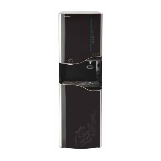
- Page 2 ICE 900 SUPPLEMENTAL MANUAL Congratulations on your choice of the ICE 900. The ICE 900 is a fully programmable self-contained unit that dispenses ice along with ambient, cold, and hot water. The versatile ICE 900 provides great tasting ice and water with every use.
-
Page 3: Table Of Contents
· Electrical and Shipping Specifications ........8 · Operating Instructions ............. 9 · Warranty ................10 SERVICE GUIDE · ICE 900 Principles of Operation ..........11 · Display and System Function Settings ........12 · LOCK/ICE Functions ............... 12 · HOT/ECONO Functions ............13 ·... -
Page 4: Safety Alert Symbols
Do not touch the power plug with wet hands or when standing in water. DANGER! ELECTRICAL SHOCK OR FIRE HAZARD. Do not install the ICE 900 in or around largely damp areas, at a place near flammable materials or at a place exposed to rain, snow, or freezing temperatures. - Page 5 TIP HAZARD. Dispenser could tip or fall causing serious injury. Do not attempt to install the ICE 900 on a surface on a sloped or unstable position. Never place heavy items on top of unit and never climb, stand, or hang on unit or storage cabinet to prevent injury and damage. Do not tilt the ICE 900 over 45°...
-
Page 6: Features And Benefits
Programmable audible controls provide user feedback and can be disabled. Leak Detection ICE 900 comes standard with a leak detection sensor at the bottom of the unit, which protects unit by closing water supply valve and alarming user if a leak is noticed. -
Page 7: Model Designations And General Specifications
MODEL/PART DESIGNATIONS BRAND NAME DESCRIPTION MODEL – PART NUMBER ICE 900 ICE 900 Ambient, Cold, Hot and Ice CHP-5070S SPECIFICATIONS ITEM ICE 900 Water Input Potable Water 39-100°F <300ppm hardness ¼” Quick Connect Input Cold-water Temperature 3°C (37°F) Thermistor Controlled Hot Water Temperature 90°C (199°F) Automatic Thermostat with 105°C (221°F) Manual Reset Hi Limit... -
Page 8: Electrical And Shipping Specifications
SHIPPING SPECIFICATIONS ITEM Width/Depth/Height of ICE 900 430 x 492 x 1490 mm (17” x 19 ½” x 50”) Weight – Dry (w/o packaging) 53.5 kg (118 pounds) Shipping Information 533 x 584 x 1575 mm (21” x 23” x 62”) -
Page 9: Operating Instructions
Hold water selection touch screen icon for 3 seconds until LED indicated water selection is active. AMBI COLD Hot Water Selection Cold-water Selection Ambient Water Selection Temperature Selection Buttons Touch to select Ice Water Dispensing Button Dispense Push Cup against pad to activate water dispense ICE 900 Supplemental Service Manual Page 9 Revision 3-19-2019... -
Page 10: Warranty
If you need service, first see the “Troubleshooting” section of the User’s Manual Guide. After checking “troubleshooting”, additional help can be found by contacting your local certified ChungHo dealer. You must provide proof of purchase or installation date for in-warranty service. 03/05 ICE 900 Supplemental Service Manual Page 10 Revision 3-19-2019... -
Page 11: Ice 900 Principles Of Operation
ICE 900 PRINCIPLES OF OPERATION The ice making system of the ICE 900 automatically operates according to designed program settings based upon inputs from the Cold-water, Ice, and Environmental Sensors. You must allow time for water fill and refrigeration system to cool before the ICE 900 will start to make ice. -
Page 12: Display And System Function Settings
The LOCK FUNCTION is a safety function that allows or prevents hot water and ice from dispensing from the ICE 900. To change LOCK setting, touch and hold the button for approximately 3 seconds until the LED light indicates the desired setting. -
Page 13: Hot/Econo Functions
10 seconds until the LED light indicates the desired setting. When in Power Saving Mode, the ICE 900 detects the amount of light surrounding the machine. Hot Water production will automatically be turned off when there is no light, and turned on when there is sufficient light surrounding the ICE 900. -
Page 14: Const Function
4. Push container against water dispensing button to start continuous dispense. To STOP CONTINUOUS DISPENSE, touch the Hot, Cold, or Ambient water selection button ICE 900 Supplemental Service Manual Page 14 Revision 3-19-2019... -
Page 15: Error Proofing The Front Display
Tip - Use black tape or Part Number 21-1280 to Cover Programming Buttons LED lights before installing decal to help prevent light from coming thru. Black Label to Cover Programming Programming Buttons Buttons Part Number 21-1280 ICE 900 Supplemental Service Manual Page 15 Revision 3-19-2019... -
Page 16: Service Requirements
900 Water Treatment System. Failure to follow the instructions in this manual could result in death, serious personal injury, or severe property damage. Only trained and qualified technicians should attempt to install, maintain, or service the ICE 900. DANGER! HIGH VOLTAGE ELECTRICAL HAZARD. Unplug before inspection and service. -
Page 17: Design Changes To Pcb And Environmental Sensor
Date of Manufacture: Prior to 7-6-2017 WLCP PN 21-1045 Iguassu PN 45-0022-0 NEW LOCATION Serial Numbers: Z-10369 and beyond Date of Manufacture: After 7-6-2017 WLCP PN 21-1046 Iguassu PN 41-1354-0 Environmental Sensor Part Number Changes ICE 900 Supplemental Service Manual Page 17 Revision 3-19-2019... - Page 18 Main PCB Design Changes The two different designs of the Main PCB are not interchangeable – verify Main PCB part number to the applicable serial number listed below. ICE 900 Supplemental Service Manual Page 18 Revision 3-19-2019...
-
Page 19: Consumables And Spare Parts
Ice Full Ice Sensor Transmitter Motor Ice Coupler – install between micro switches Circulation Pump Cold-water Level Sensor Probe Cold Water Sensor Main PCB Cold Solenoid Dispensing Solenoid Environmental Sensor Power Transformer ICE 900 Supplemental Service Manual Page 19 Revision 3-19-2019... - Page 20 CONSUMABLES AND RECOMMENDED SPARE PARTS DRAWINGS Main PCB Located under Cover Optical Level Control (Water Level Sensor) Cold Inlet Solenoid Environmental Ice Dispense Sensor Outlet ICE 900 Supplemental Service Manual Page 20 Revision 3-19-2019...
- Page 21 Every 12 months or as required. PCB to *Use this P/N for serial numbers Environmental after Z-10369. Sensor Mfg. P/N 41-1349-0 Inlet Solenoid (SV 21-1095 Every 12 months or as required. Raw Water) ICE 900 Supplemental Service Manual Page 21 Revision 3-19-2019...
- Page 22 21-1250 Front Panel Programming Sticker 21-1280 Replacement and recommended spare parts can be obtained from Waterlogic or an Authorized Waterlogic Dealer. NOTE: At the end of this product’s life, ensure that it is disposed of in an environmentally friendly manner which is fully compliant with all Federal/State/Local Requirements and Guidelines.
-
Page 23: Overview Drawing
OVERVIEW DRAWINGS ICE 900 Supplemental Service Manual Page 23 Revision 3-19-2019... -
Page 24: Flow Diagram
FLOW DIAGRAM ICE 900 Supplemental Service Manual Page 24 Revision 3-19-2019... -
Page 25: Filter Replacement
ENSURE OUTER O-RING REMAINS IS IN PLACE AT TOP OF FILTER. DO NOT DISCARD THE O-RING AT TOP OF FILTER. Failure to keep the O-ring in place will result in the filter leaking. Turn on Incoming Water Supply ICE 900 Supplemental Service Manual Page 25 Revision 3-19-2019... - Page 26 Note: Move the filter being flushed to the Sediment Filter Location to flush filter. Post Carbon Pre-Carbon Membranes *Do not flush carbon thru Sediment RO membrane ICE 900 Supplemental Service Manual Page 26 Revision 3-19-2019...
-
Page 27: Ice Tray Motor And Coupler Replacement
Note: It may be necessary to activate the drain switch to reposition the motor to reassemble the Coupler/ Motor Assembly. ICE TRAY COUPLER POSITION SWITCHES Ice releasing Function Rotating to make ice position Ice making position ICE 900 Supplemental Service Manual Page 27 Revision 3-19-2019... -
Page 28: Environmental, Cold, And Ice Sensor Replacement
Serial Numbers: Prior to Z-10368 Date of Manufacture: Prior to 7-6-2017 WLCP PN 21-1045 Iguassu PN 45-0022-0 Serial Numbers: Z-10369 and beyond Date of Manufacture: After 7-6-2017 WLCP PN 21-1046 Iguassu PN 41-1354-0 ICE 900 Supplemental Service Manual Page 28 Revision 3-19-2019... - Page 29 Access to the cooling sensor 4. Remove the two screws holding the cooling sensor in place. *Do after removing insulation. not remove the plastic water is not removed with the sensor. ICE 900 Supplemental Service Manual Page 29 Revision 3-19-2019...
- Page 30 2. Pull insulation down to 3. Locate the Ice Making Sensor access the evaporator attached to the holding clip on line. the evaporator line. 4. Remove the sensor from the holding clip and replace. ICE 900 Supplemental Service Manual Page 30 Revision 3-19-2019...
-
Page 31: Sensor Tables
Environmental Temp Sensor Table (°F) (Kꭥ) (°F) (Kꭥ) (°F) (Kꭥ) 26.6 99.5 21.8 78.5 62.5 14.9 12.4 40.3 10.4 32.6 Ice Making Time - Minutes (°F) Minutes (°F) Minutes (°F) Minutes 10.8 12.9 ICE 900 Supplemental Service Manual Page 31 Revision 3-19-2019... -
Page 32: Hot Tank Reset
Check electric resistance of hot water temp sensor and metal bimetal. Check if bimetals are affixed properly onto the hot tank’s surface. Reset Button Check heater wire connection and applied voltage. Applied voltage: AC 120V ICE 900 Supplemental Service Manual Page 32 Revision 3-19-2019... -
Page 33: Electrical Schematic
ELECTRICAL SCHEMATIC ICE 900 Supplemental Service Manual Page 33 Revision 3-19-2019... -
Page 34: Pre-Installation
· TDS Meter and Test Strips for measuring chlorine - Optional · 1/8 NPT Female Thread to ¼” Compression Fitting (Used to connect hose to drain fittings) 1. Unpack the Waterlogic ICE 900 Water Treatment System and check exterior for damage. WARNING! ICE 900 WATER TREATMENT SYSTEM IS HEAVY. - Page 35 Flushing of the filters will take place in the Sediment Filter Location Install Pre-Carbon Filter into the now empty Sediment Filter Location. Turn on Incoming Water Supply ICE 900 Supplemental Service Manual Page 35 Revision 3-19-2019...
- Page 36 Install Sentiment Filter into its location and flush as stated for Pre-Carbon Filter above. Reinstall the filters back to their correction location. The Filter Block identifies correct location of the filters. ICE 900 Supplemental Service Manual Page 36 Revision 3-19-2019...
-
Page 37: Sanitization
Ambient Tank 2-3 times to ensure that any odorous tastes left in the system lines, etc. are removed. 3. Remove the Front Bottom Cover to the ICE 900 to gain access to the main filter housing area and to reveal the filter block. - Page 38 Hot Water System. NOTE: Systems LED’s on the front panel will continuously and flash and the ICE 900 will sound while the “DRAIN” switch is in the ON position. Add one capful of household bleach to the inside of the Ambient Tank.
- Page 39 Dispense a cup of hot water to ensure the temperature/odor/taste is acceptable. WARNING! VERY HOT WATER CAN BURN OR SCALD. Hot water should be dispensed carefully into insulated container to avoid injury. ICE 900 Supplemental Service Manual Page 39 Revision 3-19-2019...
-
Page 40: Draining
DRAINING Drain the ICE 900 Water Treatment System for transportation per the Draining Instructions in this and all other supplied manuals. WARNING! STORE UNIT EMPTY. ALWAYS SANITIZE BEFORE REUSE. The unit must be completely drained and sealed before storing to avoid stagnation and reduce microbiological contamination (potential bacterial growth). - Page 41 Re-fill and drain the ambient water tank for 2-3 times to complete the flushing of the Hot Water System. Note: Systems LED’s on the front panel will continuously and flash and the ICE 900 will sound while the “DRAIN” switch is in the ON position.
-
Page 42: Installation
(potential bacterial growth). Sanitize before use to eliminate any potential microbiological contaminates The ICE 900 utilizes a Reverse Osmosis Filtration System. The unit and ice making process is calibrated to utilize the supplied filtration and requires a drain connection. Do not alter the filtration system. - Page 43 ICE 900 Water Treatment System. Always install indoors and place the ICE 900 on a firm, flat and stable surface. It is critical that the unit be level to produce consistent ice and avoid ice tray freezing issues.
-
Page 44: Condensate Pump (Drain) Installation
CONDENSATE PUMP – TYPICAL PLUMBING A 3/8” drain is located above the inlet / outlet of the ICE 900 and should be run into the (2) holding area of the condensate pump. The (3) pump outlet should then be plumbed to an available drain. -
Page 45: Error Codes
Water Full Light Flashing – Water overfill. Ice Full Light Flashing – Ice process fault. All Systems LED’s on the front panel will continuously and flash and the ICE 900 will sound while the “DRAIN” switch is in the ON position. -
Page 46: Troubleshooting Tips
TROUBLESHOOTING TIPS 1. The Ice 900 RO system and ice storage bin must both be hooked to a floor drain. You can use a one-way check valve to prevent backflow and tee the lines together to reduce overall drain line requirements.
Need help?
Do you have a question about the ICE 900 and is the answer not in the manual?
Questions and answers