Table of Contents
Advertisement
Advertisement
Table of Contents
Troubleshooting

Related Manuals for WaterLogic FIREWALL WL7


Summary of Contents for WaterLogic FIREWALL WL7
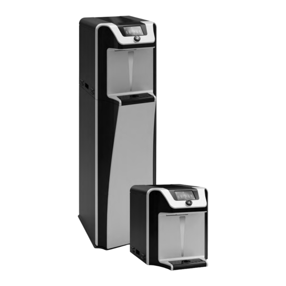
- Page 1 WL7 FIREWALL ™ Technical Manual...
- Page 2 WL7 FIREWALL ™ TECHNICAL MANUAL Waterlogic® provides water treatment in point of use water coolers using these three technologies: Firewall BioCote® antimicrobial protection High performance filtration With this in mind, this advanced water purification system combines refined engineering and high-tech features.
-
Page 3: Table Of Contents
TABLE OF CONTENTS 1 PRECAUTIONS AND GENERAL RECOMMENDATIONS SAFETY PRECAUTIONS CERTIFICATIONS 2 PRODUCT INFORMATION WL7 FW FEATURES AND BENEFITS USER INTERFACE - DISPLAY SCREEN TECHNICAL INFORMATION WATER FLOW DIAGRAM FRONT AND REAR VIEW WL7 1. External Component 2. Product Dimensions 3. -
Page 4: Precautions And General Recommendations
Ensure always the proper management and transportation of the machine to avoid damaging the refrigerant fluid and causing a dangerous leak. Use a water pressure regulator: Waterlogic will not be responsible for injury or damage caused by excessive water pressure. Input or feed pressure must be regulated to 3 bar. - Page 5 Do not touch or look directly into the faucet. The replacement of the UV-C must be done by Waterlogic or approved Waterlogic distributors and with power supply disconnected. The UV lamp must be replaced at 6 month intervals or when necessary.
-
Page 6: Certifications
Waterlogic manufacturing, Qingdao, is certified to ISO 9001:2015 by Intertek. Waterlogic water purification systems have been tested and certified to rigorous CE Standards. BPA Free: Waterlogic tests for BPA and declares that all its products are bisphenol-A FREE and contain no harmful BPA plastics. -
Page 7: Product Information
Ice Bath cooling technology: the new Ice Bath water cooling system delivers high volumes of ice-cold water, offering a high capacity solution for the most demanding most consistent cold water of the Waterlogic range. BioCote® antimicrobial protection: key surfaces surrounding the dispensing areas and drip tray are infused with an exclusive silver additive called BioCote®. -
Page 8: User Interface - Display Screen
2.2 USER INTERFACE - DISPLAY SCREEN Ambient Sparkling Cold Extra-Hot 8501 COLD Bottles Saved Rotate to select COLD · Bar with dynamic · ON hot water option, Press to dispense glowing: chiller ON. the white arrows indicate the current temperature ·... -
Page 9: Technical Information
2.3 TECHNICAL INFORMATION TECHNICAL DATA WL7 Firewall™ Features BioCote® UV Technology Firewall™ Dispense area height [mm] Energy saving mode Working information Cold water output [°C]* Sparkling water output [°C]* Hot water output [°C]* 75-93 Extra hot water output [°C]* 80-95 Ice Bath capacity [L] Sparkling tank capacity [L] Hot tank capacity [L]... - Page 10 *Filter configuration depended on incoming water conditions TECHNICAL DATA WL7 Firewall™ Model ID Description Waterlogic WL7 HCAS Mini 500W Climate Class N F-7FX-M-HCAS-HVL621NX-XX-YYY Waterlogic WL7 HCAS Mini 500W Climate Class T F-7FX-M-HCAS-HVL621TX-XX-YYY Waterlogic WL7 HCAS Mini 800W Climate Class N...
-
Page 11: Water Flow Diagram
2.4 WATER FLOW DIAGRAM These diagrams are for reference and understanding the WL7 FW, some features might not be included on your machine. More detailed information can be seen in Chapter 6.1 and electrical diagram on Chapter 6.3. Water configuration: cold, sparkling, ambient and hot. CHECK VALVE HOT WATER OUT VENT PIPE... - Page 12 These diagrams are for reference only; some features might not be included on your machine. More detailed information can be seen in Chapter 6.1 and electrical diagram on Chapter 6.3. Water configuration: cold, ambient and hot. HOT WATER OUT VENT PIPE IN (Water) COLD WATER OUT TANK...
-
Page 13: Front And Rear View Wl7
2.5 FRONT AND REAR VIEW 1 EXTERNAL COMPONENT Description WL7 - Top Housing Insert- Glossy Black WL7 - Metal Top cover WL7 - Right side panel Plastic Handle Black WL7 - Drip Tray WL7 - Drip Tray Grill WL7 - Back Splash Trim WL7 - Waterfall Light Diffuser WL7 - Door Parent Part WL7 - UI Insert Trim... -
Page 14: Product Dimensions
2 PRODUCT DIMENSIONS 397 mm 519 mm 399 mm 401 mm 3 PRODUCT LABEL To identify your product characteristics and production date you can refer to the examples below: Model: F-7FX-M-HCAS-HVL621NX-XX-YYY Machine Model S / N: LB2H634SB18C13004CN1 Year: 18 Month: A->L (Jan->Dec) C: March Day: 13 Machine Number: 004... -
Page 15: Installation Information
• A 350kpa pressure reducing valve and dual check valve must be connected at the water supply. • The Waterlogic units should not be connected to water supplies of unknown bacterial quality or those not already fit for human consumption. The Waterlogic units should only be connected to a potable drinking water supply. - Page 16 • The isolation for the water and electricity should be easily accessible, and the machine should not be installed using an extension lead. • The water outlet connection must be fitted with an install kit containing a non-return valve, a pressure reducer (maximum 3 bar) and a water block device. Prepare the connection to the machine from the install kit via a length of 1/4”...
-
Page 17: Sanitising Instructions
3.2 SANITISING INSTRUCTIONS The disinfection of the product after installation is very important to ensure that there is no residue on the machine due to transport and testing that can leave a bad taste in the water. Always ensure proper ventilation and use proper personal protective equipment such as gloves and eye protection when using chemicals. - Page 18 Wait 10 minutes. After, flush at least 5 litres of cold water and use test strips to make Flush 5 litres of ambient and sparkling until sure there is no sanitiser left. there is no sanitiser in the system. After the sanitiser has been completely flushed the green compressor and heater switch can now be turned ON.
-
Page 19: Installation
3.3 CO INSTALLATION EQUIPMENT UNDER PRESSURE, HANDLE WITH CARE For the replacement of the CO cylinder, all the operations must be carried out exclusively by qualified technical personnel. The cylinders must not be lifted by the cap, or dragged, rolled or slid along the floor. Even short distances, an appropriate hand cart or other suitable means of transport should be used. -
Page 20: Contactless
3.4 CONTACTLESS In this chapter, you will be guided through the process of installing the contactless solution. If you have any questions during this process, please reach out to your Regional Technical Manager at support@waterlogicsupport.zendesk.com. All work must be carried out with the water and electricity disconnected. Prior to commencing work, please refer to the below instructions carefully. - Page 21 • Refit UI PCB cover/housing to machine. • Remove 2 screws shown to remove UI PCB from housing/cover. Reverse steps to fit new UI PCB. • Knock through the protective cover shown. • • Feed harness through opening shown in •...
-
Page 22: Service Procedures
WL7 FW is equipped with labels to help correctly identify the components, replace these labels when damaged. Use only Waterlogic replacement parts that can be obtained from Waterlogic or an authorized Waterlogic distributor, failure to do so will void the warranty. -
Page 23: Verifying The Correct Operation Of The Machine
4. 2 VERIFYING THE CORRECT OPERATION OF THE MACHINE Before doing the scheduled service on the machine, ensure that the machine is in perfect working conditions by following the steps below. Check the exterior of the machine for Check if the water supply is open (if it is damage. -
Page 24: Hot Tank Descaling Instructions
• ¼” plastic tubing, at least 1 meter (3 to 4 feet) in length, and assorted ¼” quick connect fittings. • Inline descaling/sanitizing cartridge or Waterlogic filter without media. DESCALING STEPS Open the front panel [9] to access the filter. - Page 25 Ensure the green compressor and heater Turn ON the water supply. switch is ON [22]. Dispense hot water until water with descale Pinch the dispensing tube or block the hot dispense and dispense hot water until water comes out the faucet by the vent hole. solution comes out the faucet.
- Page 26 Turn ON the water supply and dispense Turn the green compressor and heater hot water to flush the remaining descaler. switch [22] ON and allow the hot tank to Repeat step 8 to clean the ventilation tank heat up. Dispense to a glass and check the flush until water runs clear.
-
Page 27: Filter Replacement
4. 4 FILTER REPLACEMENT The filters must be replaced every 6 months and FLUSHED before being connected to the machine. Turn Off water supply. Dispense to relieve the water pressure. Ensure the new filters are flushed before Open the front panel [9] to access the filter. step 4 and 5. -
Page 28: Uv Lamp Replacement
4. 5 UV LAMP REPLACEMENT The UV lamp can cause harm if improperly used, please check the safety precautions before attempting to replace the UV lamp. Disconnect the power cable [25]. Turn OFF both green and red switches [22] & [23]. Open the front door chapter 2.5 [9] and Pull the UV lamp carefully. -
Page 29: Programming And Special Features
5. PROGRAMMING AND SPECIAL FEATURES 5. 1 PROGRAMMING INSTRUCTIONS One of the features present in the WL7 FW is the maintenance screen (see below). To access the screen, choose the ambient dispensing icon and press 5 times for 5 seconds. This screen allows to check the settings of the machine: •... -
Page 30: Hot Water Setpoint
1. Hot water setpoint The hot water comes with the default setpoint of 87°C. To change this value, change the DIP switches like shown below to get 75°C or 93°C. 87°C 75°C 93°C DEFAULT 2. Extra hot water setpoint The extra hot water comes with the default setpoint of of 95°C. To change this value, change the DIP switches like shown below to get 87°C or 80°C. -
Page 31: Energy Saving
4. Energy saving All WL7 Firewall™ water purification systems come from the factory with energy saving sleep mode enabled to meet the Energy Star certification requirements. Energy saving sleep mode disables the heater circuit when the unit has not been used for a continuous period of 3 hours. -
Page 32: Model Configuration
5. 2 MODEL CONFIGURATION WL7 FW model configuration can be altered by adjusting the switch DP1 on the back side of the display PCB. Hot and sparkling models require associated internal components at time of purchase. WL7 FW DISPLAY PCB (BACK VIEW) Cold and ambient Cold, ambient Cold, ambient,... -
Page 33: Schematics
6. SCHEMATICS ENG2036-16/01/19... -
Page 34: Hydraulic Components
6. 1 HYDRAULIC COMPONENTS This images complement the flow diagram in chapter 2.4. ENG2036-15/01/19... - Page 35 Description Description JG Bulkhead Connector Union 1/4" JG Equal Tee Connector 1/4" 1/4" PE Pipe 1/4" PE Pipe JG Equal Straight Connector 1/4" JG Equal Elbow Connector 1/4" MS DC Solenoid Valve SWV24-02 FW Assembly JG Equal Elbow Connector 1/4 1/4"...
-
Page 36: Exploded View Diagram And Parts List
6. 2 EXPLODED VIEW DIAGRAM AND PARTS LIST 58 59 39 38 SCHEMATICS ENG2036-15/01/19... - Page 37 No Description Description WL7 - Top Housing Insert- WL7 - Hinge WL7 - Metal Top cover WL7- waterfall light backing JG Bulkhead Connector Union 1/4" WL7 - Door latch Switch - (Red) WL7 adjustment pin for door parent Switch - Heater/Compressor (Green) WL7 - Spring for Door Latch MS DC Solenoid Valve SWV24-02 Fuse Holder &...
-
Page 38: Electrical Diagram
6.3 ELECTRICAL DIAGRAM HIGH VOLTAGE ELECTRICAL HAZARD WL7 Firewall™ Unit and PCB (Printed Circuit Board) contain high voltage hazard. Only trained and qualified technicians should attempt live testing and troubleshooting. Electrical Diagram 230V The diagram below complements the flow diagram in chapter 2.4. Mark Description Mark... - Page 39 HIGH VOLTAGE ELECTRICAL HAZARD WL7 Firewall™ Unit and PCB (Printed Circuit Board) contain high voltage hazard. Only trained and qualified technicians should attempt live testing and troubleshooting. Electrical Diagram 120V Mark Description Mark Description Power Fuse Ice Probes PCB Safe Power Switch Intensity of Ultraviolet Detection Main Power Switch S.
-
Page 40: Troubleshooting
7. TROUBLESHOOTING The reference numbers in between “[]” in this chapter refer to chapter 2.5. 7. 1 RESETTING THE HOT TANK HIGH LIMIT SAFETY Turn OFF both red [23] and green [22] Unplug the power cord from the rear of unit [25]. -
Page 41: Uv Error
7. 2 UV ERROR • The UV sensor is not detecting UV light to ensure safe water. • Cold, sparkling, and ambient (room temperature) icons will be ghosted in the dispense screen. COMMON TROUBLESHOOTING: 1. UV lamp – a) Status; b) Intensity; c) Connections 2. -
Page 42: Ice Detection Error
7.5 ICE DETECTION ERROR • The ice detection sensor has a short circuit or open circuit. • Refrigeration compressor will be shut off and cold and sparkling icons will be ghosted in the dispense screen. COMMON TROUBLESHOOTING: 1. Ensure the Ice Bath is above 30 ppm Total Dissolved Solids (TDS). Add ½ teaspoon of sodium bicarbonate to the Ice Bath from the top access if necessary. -
Page 43: Ice Bath Circulation Error
7.7 ICE BATH CIRCULATION ERROR • The circulation motor in the ice bath has faulted COMMON TROUBLESHOOTING: 1. Cycle power to ensure error repeats (RESET). 2. Check all wiring to ensure there is not an open circuit. 3. Replace circulation motor (chapter 6.1, [83]). RESET the ERROR by turning OFF and ON after 5 seconds the red power switch. -
Page 44: Power To The Machine
7.10 NO POWER TO THE MACHINE Symptoms Causes Solutions Circuit Breaker Check the circuit breaker Replace fuse [24] · Red switch Check that power cord Fuse is blown defective/loose not lit is properly plugged in [25]. power cord. · Green If it is properly plugged in, use a switch not lit different power cord to verify. -
Page 45: Cold Water Troubleshooting
7.11 COLD WATER TROUBLESHOOTING If the cold water temperature is above 12°C or at the same temperature as the ambient water, follow the instructions below. Symptoms Causes Solutions Wait for the tank to recover Too much dispensing in before dispensing more a small time depleted the Compressor is running, and cold water, assure that the... -
Page 46: Hot Water Troubleshooting
7.12 HOT WATER TROUBLESHOOTING Before starting with the troubleshooting check in the maintenance screen (Chapter 5.1-) if the hot water setpoint is the correct for the type of usage. The setpoint can be changed to ensure specific demands. Symptoms Causes Solutions Wake the Machine out of Sleep No power... -
Page 47: Dispensing Troubleshooting
7.13 DISPENSING TROUBLESHOOTING Symptoms Causes Solutions Too much water pressure. Recom- Adjust water pressure to 2.7-3.5Bar. mend 2.7 – 3.5 Bar for WL7 FW water treatment system to operate Irregular/ Open and Clean the Inlet and Out- Dirty Solenoid Intermittent let Solenoid Dispensing Faulty Solenoid...
Need help?
Do you have a question about the FIREWALL WL7 and is the answer not in the manual?
Questions and answers
Turn hot water off at dip switch settings