Table of Contents
Advertisement
Quick Links
Advertisement
Table of Contents
Troubleshooting

Related Manuals for Toshiba TDP-S3


Summary of Contents for Toshiba TDP-S3
- Page 1 FILE NO. 330-200106 DOCUMENT CREATED IN JAPAN, Nov., 2001...
-
Page 2: Safety Precaution
ULTRAVIOLET DANGER IN SERVICE MODE Eye damage may result from directly viewing the light produced by the lamp used in this product. Always turn off lamp before opening this cover. Ultraviolet radiation eye protection required during servicing. TDP-T3 / TDP-S3 / TDP-MT5 Service Manual... -
Page 3: Table Of Contents
Table of Contents ......................3 Safety Precautions ......................5 Important Precautions ....................5 Important Safety Instructions ..................6 Introducing the TDP-T3, TDP-S3 and TDP-MT5 ............7 Parts Replacement ......................8 Replaceable Part Hierarchy ....................8 Exploded views ........................9 Remove and replace the focus and zoom rings..............11 Remove and the front bezel and front bezel vent ...............13... - Page 4 Check the color wheel and reseat the cable ...............94 Using the keypad to power up the projector................98 Parts Lists........................100 Replaceable parts by alphabetic listing................100 Replaceable parts by numeric listing ................103 Fasteners and Torque Settings..................106 Standard Accessories .......................107 TDP-S3/TDP-T3/TDP-MT5 Service Manual...
-
Page 5: Safety Precautions
The exclamation point within an WARNING: Changes or modifications made to this equipment, not expressly approved by equilateral triangle is intended to Toshiba, or parties authorized by Toshiba, could void the user's authority to operate alert the user to the presence of the equipment. -
Page 6: Important Safety Instructions
IMPORTANT SAFETY INSTRUCTIONS CAUTION: PLEASE READ AND OBSERVE 1. Read Owner's Manual 3. Source of Light ALLWARNINGS AND After unpacking this product, read the Do not look into the lens while the lamp INSTRUCTIONS GIVEN IN THIS owner's manual carefully, and follow all is on. -
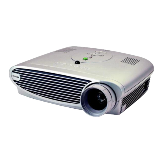
Page 7: Introducing The Tdp-T3, Tdp-S3 And Tdp-Mt5
The TDP-T3, the TDP-S3 and the TDP-MT5 projectors use DLP (digital light processing) technology from Texas Instruments. The TDP-T3 has a native XGA resolution (1,064 x 768 pixels), while the TDP-S3 has a native SVGA resolution (800 x 600 pixels). Both the T3 and S3 have 2000 lumens (or 1600 in conservation mode). The TDP-MT5 is optimized for video reproduction with 848 x 480 (16:9) and 800 x 600 (4:3) resolutions. -
Page 8: Parts Replacement
Bottom Case Front Bezel Vent Safety Switch Assembly Top Case Front Bezel Lamp blower Keypad Chassis Lamp Fan Speaker Power Supply Rear Bezel Power Supply Fan Controller ECA Power Supply Fuse Chassis & Power Supply I/O Shield TDP-S3/TDP-T3/TDP-MT5 Service Manual... -
Page 9: Exploded Views
Exploded views Case parts Below is an exploded view of the case parts in the TDP-T3/S3/MT5. Top case Keypad Rear bezel Bottom case Lamp door Front bezel Zoom ring Front bezel vent Focus ring Name plate TDP-S3/TDP-T3/TDP-MT5 Service Manual... - Page 10 Below is an exploded view of the main components in the TDP-T3/S3/MT5. Keypad Controller ECA Power supply fan Chassis Power supply Lamp blower (part of engine) Lamp fan (part of engine) Optical engine Front fan (part of engine) Lamp module TDP-S3/TDP-T3/TDP-MT5 Service Manual...
-
Page 11: Remove And Replace The Focus And Zoom Rings
Both rings have three slots or tabs that align with pins or slots on the lens barrel. ♦ Align the tabs on the zoom ring with the three slots on the lens barrel, and then press it into place. It should fit close to the front bezel, but should not touch the bezel. TDP-S3/TDP-T3/TDP-MT5 Service Manual... - Page 12 Depending on the focus setting, the focus ring may not appear to fully seat itself. Turn the ring clockwise. It should move inward until it nearly touches the zoom ring. ♦ Place the lens cap over the focus ring. TDP-S3/TDP-T3/TDP-MT5 Service Manual...
-
Page 13: Remove And The Front Bezel And Front Bezel Vent
The front bezel (TDP-S3/T3: 505-0972-xx;TDP-MT5: 505-1193-xx) fastens to the front of the projector. The front bezel vent (TDP-S3/T3: 505-0969-xx; TDP-MT5: 505-1195-xx), in turn, fastens to the front bezel. The Toshiba nameplate (TDP-S3/T3, 505-1060-xx; TDP-MT5, 505-1197-xx) snaps to the front of the front bezel vent. - Page 14 You may need to use a small bladed screw driver to pry it up. Use a T-10 driver to remove the two black M3x8 Torx screws that fasten the front bezel to the projector near the lens. TDP-S3/TDP-T3/TDP-MT5 Service Manual...
- Page 15 Use a T-10 driver to remove the black M3x48 cone point Torx screw from the bottom of the projector adjacent to the lamp door. Lift the end of the front bezel near the lamp first, then swing it out to disengage the other end. TDP-S3/TDP-T3/TDP-MT5 Service Manual...
- Page 16 To install the bezel vent, slide the end nearest the lens toward the lens so that the two tabs on the front bezel engage the first vertical louver on the inside of the vent. ♦ Torque the M3x14 Torx screw on the bezel vent to 6 in.-lbs (.45 Nm). TDP-S3/TDP-T3/TDP-MT5 Service Manual...
-
Page 17: Remove And Replace The Lamp Door And Lamp Module
A frame made of metal and plastic holds the reflector assembly in place inside the projector. The lamp door (TDP-S3/T3: 505-0978-xx; TDP-MT5: 505-1196-xx) fits over the lamp cavity. It includes a tab that closes the interlock switch when the door is shut. - Page 18 Torque the two captive screws to 6 in.-lbs. (.678 Nm). ♦ Make sure the bail on the lamp module is folded down in storage position. It snaps into position. ♦ You must replace the lamp door for the projector to operate. TDP-S3/TDP-T3/TDP-MT5 Service Manual...
- Page 19 Source button. Hold both buttons down for five seconds. To verify that the lamp timer is reset, press the Menu button and navigate to the Source menu. The lamp timer is the first item on the list. TDP-S3/TDP-T3/TDP-MT5 Service Manual...
-
Page 20: Remove And Replace The Top Case
Remove and replace the top case The top case (TDP-S3/T3: 505-0982-xx; TDP-MT5: 505-1188-xx) covers the top half of the half of the projector. Once you remove the top case, you have access to FRUs inside the projector. A new top case also includes the IR ECA and cable. - Page 21 Lift the side of the case opposite the projection lens. Take care as you swing the case open: cables run between the top case and controller ECA. Disengage the hinges on the side of the top case closest to the lens. TDP-S3/TDP-T3/TDP-MT5 Service Manual...
- Page 22 Connect the keypad and IR cables first. Then engage the hinges on the lens side of the projector. ♦ Swing the top case shut, making sure that it fits flush over the bottom case. ♦ Torque the black M3x48 cone point Torx screw to 4 in.-lbs. (.452 Nm) TDP-S3/TDP-T3/TDP-MT5 Service Manual...
-
Page 23: Remove And Replace The Keypad
When you install the keypad, make sure that the alignment pins in the top case fit into the holes at each end of the keypad ECA. ♦ Torque the two black M3x6 Plastite Torx screws to 4 in.-lbs. (.452 Nm). TDP-S3/TDP-T3/TDP-MT5 Service Manual... -
Page 24: Remove And Replace The Front Fan
Front bezel and bezel vent (see page 13) Top case (see page 20) Unplug the front fan cable from connector J508 and the lamp blower cable from connector J507 on the controller ECA. Untwist the fan cable from the blower cable. TDP-S3/TDP-T3/TDP-MT5 Service Manual... - Page 25 See the illustration above. ♦ Torque the two screws to 6 in/lbs (.68 Nm). ♦ Twist the fan and blower cables together. Plug the blower cable into connector J507 and the fan cable into connector J508 on the controller ECA. TDP-S3/TDP-T3/TDP-MT5 Service Manual...
-
Page 26: Remove And Replace The Speaker Assembly
Top case (see page 20) Use a T-10 driver to remove the M3x8 Torx screw that fastens the speaker to the chassis. Move the speaker assembly aside and unplug the speaker cable from its connector on the controller ECA. TDP-S3/TDP-T3/TDP-MT5 Service Manual... - Page 27 Remove the two black M3x6 Plastite Torx screws from the top of the speaker assembly. Then separate the speaker and gasket by pressing the bottom of the speaker up through the top of the assembly. TDP-S3/TDP-T3/TDP-MT5 Service Manual...
- Page 28 Mount the speaker assembly in the projector so the two posts on the chassis mate with the two recesses on the bottom of the speaker bracket. The mounting arm faces the front of the projector. Torque the M3x8 Torx screw to 6 in/lbs (.68 Nm). TDP-S3/TDP-T3/TDP-MT5 Service Manual...
-
Page 29: Remove The Controller Eca
Remove the controller ECA The controller ECA (TDP-S3: 510-1579-xx; TDP-T3: 510-1530-xx) mounts to the top of the metal chassis above the optical engine and power supply. It is fastens to the chassis with eight screws, and it connects to the DMD ECA on the optical engine through a direct connector on the bottom of the controller. - Page 30 Unplug the controller/power supply cable from the corner of the controller ECA adjacent to where the speaker was located. Squeeze the latch on the bottom of the connector to release it. Remove the eight M3x8 Torx screws that fasten the controller ECA to the chassis. TDP-S3/TDP-T3/TDP-MT5 Service Manual...
- Page 31 WARNING Make sure to store the controller ECA in a static-safe container. If you are replacing the controller with a new one, remove the I/O EMI shield (see page 34). For information on installing the controller ECA, see page 32. TDP-S3/TDP-T3/TDP-MT5 Service Manual...
-
Page 32: Install The Controller Eca
WARNING Be sure to take proper ESD precautions while working near the controller ECA. It can be easily damaged by static electricity. Slide the rear of the controller ECA into place first so that the I/O connectors align with the holes in the rear bezel. TDP-S3/TDP-T3/TDP-MT5 Service Manual... - Page 33 Align the controller/DMD connector, then press the controller down firmly. You will feel the connector halves engage. TDP-S3/TDP-T3/TDP-MT5 Service Manual...
- Page 34 Go to page 94 if you need help with the color wheel cable. When you reassemble the projector, make sure you flash the unit with the latest Toshiba software. If you do not flash the projector, the incorrect splash screen will appear.
-
Page 35: Remove And Replace The I/O Emi Shield
Assembly Notes ♦ Make sure the fingers on the shield contact the connectors. ♦ Torque the jack screws to 2 in-lbs (.226 Nm). ♦ For information about installing the controller ECA, see page 32. TDP-S3/TDP-T3/TDP-MT5 Service Manual... -
Page 36: Remove And Replace The Chassis And Power Supply
Use a T-10 driver to remove the two M3x8 Torx screws near the front of the chassis, and the two M3x8 Plastite Torx screws near the rear of the chassis. Unplug the white safety cable inline connector adjacent to the lamp housing. TDP-S3/TDP-T3/TDP-MT5 Service Manual... - Page 37 Remove the lamp cable from the lamp connector on the lamp housing. To do this, remove the two M3x8 Torx screws, then lift the connector out. Lift one side of the rear bezel while flexing the bottom case slightly outward. TDP-S3/TDP-T3/TDP-MT5 Service Manual...
- Page 38 Click the part you want to remove from the list below: Power supply fan and interlock switch cable (see page 52) Power supply fuse (see page 54) Power supply (see page 48) Rear bezel (see page 40) TDP-S3/TDP-T3/TDP-MT5 Service Manual...
- Page 39 Make sure to connect the inline safety cable connector. If this cable is disconnected, the projector will not generate a lamp enable signal. ♦ Note that the lamp cable connector is keyed so that it fits into its hole in the lamp housing only one way. TDP-S3/TDP-T3/TDP-MT5 Service Manual...
-
Page 40: Remove And Replace The Rear Bezel
(020-1177-xx) adheres to the outside of the rear bezel. When you access the rear bezel, you also remove the power supply insulator (TDP-S3/T3: 329-0268-xx TDP-MT5: 329-0321-xx), the diode gap pad (329-0301-xx), and the diode heat sink bracket (330-0724- xx). - Page 41 Lift the paper power supply insulator off of the chassis. Remove the two M3x8 Torx screws that fasten the rear bezel to the chassis, then slide the bezel off of the chassis. TDP-S3/TDP-T3/TDP-MT5 Service Manual...
- Page 42 To mount the rear bezel on the chassis, align the two tabs on the inside of the bezel with the two recesses on the chassis. Alignment pins in each recess engage holes in each tab. Torque the two M3x8 Torx screws to 6 in/lbs (.68 Nm) TDP-S3/TDP-T3/TDP-MT5 Service Manual...
-
Page 43: Remove And Replace The Chassis
You are left with the bare chassis. Assembly Notes ♦ Install the ground clip before you install the chassis and parts in the bottom case. ♦ Torque the M3x6 Torx screw on the ground clip to 6 in/lbs (.68 Nm). TDP-S3/TDP-T3/TDP-MT5 Service Manual... -
Page 44: Remove And Replace The Lamp Fan
Before installing the new lamp fan, you must adhere a heat shield to the center of the fan. The heat shield must be placed over the label that is already on the fan. This side points toward the fan. TDP-S3/TDP-T3/TDP-MT5 Service Manual... - Page 45 To install the lamp fan on the lamp housing, orient the fan so that the cable emerges from the top right corner as you face the fan. The heat shield must face inward. Pins on the lamp housing match two holes in the fan. ♦ Torque the M3x12 Torx Plastite screws to 6 in/lbs (.68 Nm). TDP-S3/TDP-T3/TDP-MT5 Service Manual...
-
Page 46: Remove And Replace The Lamp Blower
Make sure the blower gasket remains in position on the lamp housing. The gasket must be in place before installing a new blower. Assembly Notes ♦ Adhere a heat shield (329-0337-xx) to the portion of the fan housing that is inserted into the lamp housing. TDP-S3/TDP-T3/TDP-MT5 Service Manual... - Page 47 Position the blower so that the pointed end is inserted into the lamp housing, and the holes on the mounting tab fit over the registration pins on the lamp housing. Torque the M3x8 Plastite Torx screw to 6 in/lbs (.68 Nm). TDP-S3/TDP-T3/TDP-MT5 Service Manual...
-
Page 48: Remove And Replace The Power Supply
Squeeze the latch on the bottom of the connector to release it. Turn the chassis over so that the power supply faces upward. Unplug the safety switch cable (211-0162-xx) from its connector on the power supply. TDP-S3/TDP-T3/TDP-MT5 Service Manual... - Page 49 A tab in the center of the bezel fits over the power supply ECA. When you flex the bezel, the ECA clears the tab, and you can lift the power supply out of the chassis. TDP-S3/TDP-T3/TDP-MT5 Service Manual...
- Page 50 40. NOTE The gap pad may stick to the bottom of the power supply when you remove it. Make sure you replace the gap pad if it comes off of the chassis. TDP-S3/TDP-T3/TDP-MT5 Service Manual...
- Page 51 Connect the ground wire to the post near the AC connector. Make sure that you route the wire as shown below. ♦ Connect the interlock switch cable to its connector on the front of the power supply. See step 4 above. TDP-S3/TDP-T3/TDP-MT5 Service Manual...
-
Page 52: Remove And Replace The Power Supply Fan And Safety Switch Cable
Unplug the safety switch cable from its connector on the power supply Turn the chassis and power supply over on the work surface. To remove the safety switch cable, lift it out of the three cable retainers on the chassis. TDP-S3/TDP-T3/TDP-MT5 Service Manual... - Page 53 Make sure to route all the cables through the cable retainers on the top of the chassis. ♦ Make sure you leave enough of the safety switch cable exposed on the power supply end so that you do not strain the cable when you plug the connector in. TDP-S3/TDP-T3/TDP-MT5 Service Manual...
-
Page 54: Remove And Replace The Power Supply Fuse
Pry the fuse out of its holder with a tweezers or small bladed screwdriver. Assembly Note ♦ Make sure that the fuse is fully inserted in the fuse holder. The top of the fuse should rest against the stop on the top of the fuse holder. TDP-S3/TDP-T3/TDP-MT5 Service Manual... -
Page 55: Remove And Replace The Safety Switch Assembly
Press firmly as you turn the screw so as not to strip the screw head. Use a small bladed screwdriver to remove the clip that fastens the thermal switch to the top of the lamp housing. The switch assembly can now be removed from the bottom case. TDP-S3/TDP-T3/TDP-MT5 Service Manual... - Page 56 The curved portion of the metal contact fits into the slot just below the screw on the lamp fan. A tab on the lamp door fits through the slot to close the interlock switch when the lamp door is in place. TDP-S3/TDP-T3/TDP-MT5 Service Manual...
-
Page 57: Remove And Replace The Optical Engine
Remove and replace the optical engine The optical engine (TDP-S3: 505-1181-xx; TDP-T3: 505-1180-xx; TDP-MT5 505-1173-xx) fastens to the bottom case. The engine comprises all parts in the light path, including the lamp housing, three fans, the metal engine, and the projection lens. - Page 58 Make sure the engine sits flush with the three posts in the bottom case. Torque the three M3x8 Plastite Torx screws to 6 in/lbs (.68 Nm). ♦ When installing a new optical engine, apply a piece of focus ring adhesive (329-0285-xx) to the front of the lens barrel. TDP-S3/TDP-T3/TDP-MT5 Service Manual...
-
Page 59: Remove And Replace The Bottom Case
The bottom case (505-0970-xx) encloses the bottom half of the projector. A new bottom case also includes the rubber foot, elevator, leveling foot, light block louver and the engine mount spacer. When you replace a bottom case, you also need to adhere a new certification label (TDP-S3: 020-1271-xx; TDP- T3: 020-1165-xx; TDP-MT5: 020-1350-xx). -
Page 60: Software
The illustrations below refer to version 2.0 of the TDP-T3 system software. The version of the software you download may be different. In the File Download box, select Save This Program To Disk option, then click OK. TDP-S3/TDP-T3/TDP-MT5 Service Manual... -
Page 61: Install The Software On The Computer
Open Windows Explorer on your computer. To do this, click the Start button, point to Programs, then click Windows Explorer. In Windows Explorer, locate the .EXE file that contains the upgrade files. Double-click the file to extract the contents. TDP-S3/TDP-T3/TDP-MT5 Service Manual... - Page 62 Follow steps five through seven if you are using Windows 98. If you are using a computer that runs on Windows 2000, steps five through seven are not necessary. In Windows Explorer, navigate to the folder C:\T3\v2.9 (or the directory in which you saved the file, if different). TDP-S3/TDP-T3/TDP-MT5 Service Manual...
- Page 63 Move the following files: ♦ Place IFCBULK in C:\Windows\INF ♦ Place ifcUsb.sys in C:\Windows\System32\Driver Restart your computer. Now you’re ready to upgrade the software in the projector. TDP-S3/TDP-T3/TDP-MT5 Service Manual...
-
Page 64: Upgrading The Software In The Tdp-T3
The instructions below apply to both the TDP-S3, the TDP-T3 and the TDP-MT5. The TDP-T3 is referenced in the examples, but they apply to the TDP-S3 Mt-5 as well. The only difference is that the three projectors use different software. - Page 65 The FlashUSB dialog box opens, ready to begin the upgrade process. Click the Select Files button in the FlashUSB dialog box. TDP-S3/TDP-T3/TDP-MT5 Service Manual...
- Page 66 The upgrade files appear in the File List box, and the Status indicator at the bottom of the dialog box reads Connecting..This tells you that the computer is attempting to establish a connection with the projector. Click the Config button. The FlashUSB Configuration dialog box opens. TDP-S3/TDP-T3/TDP-MT5 Service Manual...
- Page 67 In the FlashUSB v1.2 dialog box, The Status: Connecting… message changes to Status: Connected. The Download button becomes available. The Status indicator now says Connected..., telling you that the computer is communicating with the projector. TDP-S3/TDP-T3/TDP-MT5 Service Manual...
- Page 68 Click the Download button. The software begins downloading to the projector. The process may take several minutes. When the download is complete, the FlashUSB dialog box closes, and the projector lamp lights. The Toshiba splash screen appears. TDP-S3/TDP-T3/TDP-MT5 Service Manual...
- Page 69 44 = GUI code v4.4 13 = data configuration v1.3 21 = EDID version 2.1 The version number you see should match the series of version numbers for each HEX file in the file you downloaded from the Toshiba web site. TDP-S3/TDP-T3/TDP-MT5 Service Manual...
-
Page 70: Functional Tests
S-video capability player should also have a Composite video output port (RCA). Toshiba strongly suggests you use a DVD player to test the video quality. DVD players reproduce colors better and project sharper images. The least preferable is a VCR. If you must use a VCR, make sure you use a commercially produced recording, not one recorded from a broadcast source. - Page 71 Verify that the images project synchronize properly through both of the 3 computer images. These following inputs: will confirm that the M1 Analog computer input works M1 Digital properly, and will test image quality. Press the Computer button on the keypad. TDP-S3/TDP-T3/TDP-MT5 Service Manual...
- Page 72 Verify that the bars are not flashing. Verify that the transitions from light to dark are smooth and gradual. Image #4: SMPTE133 Project the SMPTE133 image. Verify that there are no noise, tint, duplicating columns, or other general image abnormalities present TDP-S3/TDP-T3/TDP-MT5 Service Manual...
- Page 73 Reset All. Click here for module functional tests Expansion module Power Down Verify unit is powered off before disconnecting cables. After all tests are complete turn the power off and disconnect all cables. Attach the lens cap. TDP-S3/TDP-T3/TDP-MT5 Service Manual...
-
Page 74: Troubleshooting
Troubleshooting You use this section to diagnose problems the TDP-S3, TDP-T3 and TDP-MT5 projectors. In addition to the troubleshooting trees on the following pages, you will also find the following items: ♦ Block diagram (page 88) ♦ How to power up the projector with the top off to check fan operation and voltages (page 89) ♦... -
Page 75: Troubleshooting Power Problems
Troubleshooting Power Problems Dead. No signs of power (page 36) TDP-S3/TDP-T3/TDP-MT5 Service Manual... - Page 76 Fans. No lamp. (page 89) (page 36) (page 29) (page 89) (page 36) TDP-S3/TDP-T3/TDP-MT5 Service Manual...
- Page 77 Fans and color wheel start. Then projector shuts down. (page 17) (page 52) (page 55) TDP-S3/TDP-T3/TDP-MT5 Service Manual...
- Page 78 LED blinks green. No lamp, no fans. (page 48) (page 89) (page 94) (page 29) (page 29) (page 57) TDP-S3/TDP-T3/TDP-MT5 Service Manual...
- Page 79 Fans & lamp start, then shut down. (page 89) (page 29) TDP-S3/TDP-T3/TDP-MT5 Service Manual...
- Page 80 Shuts down after running a few minutes (page 93) (page 55) (page 48) (page 29) TDP-S3/TDP-T3/TDP-MT5 Service Manual...
-
Page 81: Troubleshooting Image Problems
Troubleshooting Image Problems No image (page 29) (page 57) TDP-S3/TDP-T3/TDP-MT5 Service Manual... - Page 82 Bad color, distortion, torn or frozen image (page 29) TDP-S3/TDP-T3/TDP-MT5 Service Manual...
- Page 83 Dim image (page 17) (page 29) (page 57) TDP-S3/TDP-T3/TDP-MT5 Service Manual...
-
Page 84: Troubleshooting Keypad Problems
Troubleshooting Keypad Problems (page 23) (page 29) TDP-S3/TDP-T3/TDP-MT5 Service Manual... -
Page 85: Troubleshooting Remote Problems
Troubleshooting Remote Problems (page 20) (page 29) TDP-S3/TDP-T3/TDP-MT5 Service Manual... -
Page 86: Troubleshooting Menu Problems
Troubleshooting Menu Problems (page 85) (page 84) (page 29) TDP-S3/TDP-T3/TDP-MT5 Service Manual... -
Page 87: Troubleshooting Audio Problems
Troubleshooting Audio Problems (page 24) (page 24) (page 24) (page 29) TDP-S3/TDP-T3/TDP-MT5 Service Manual... -
Page 88: Block Diagram
RS232 Color wheel Receiver 8 Mb Flash Deinter- lacer SVideo Video Fan fail Lamp blower Decoder Composite Lamp fan Fan fail control Front fan Fan fail Power supply fan Fan fail Audio mixer Amplifier Speaker Audio In TDP-S3/TDP-T3/TDP-MT5 Service Manual... -
Page 89: Check Controller Voltages
Check controller voltages TDP-S3/TDP-T3/TDP-MT5 Service Manual... -
Page 90: Power Up With Top Case Removed To Check Fans And Voltages
Be very careful where you probe and where you touch. Do one or all of the following: Check controller ECA voltages (see page 89). Check the thermal switch (see page 93). Follow the directions below to check fan and blower operation. TDP-S3/TDP-T3/TDP-MT5 Service Manual... - Page 91 The three fans and the lamp blower should all start up when the Lamp button is pressed. See the illustrations below for the fan and blower locations. TDP-S3/TDP-T3/TDP-MT5 Service Manual...
- Page 92 To verify that a fan or blower is bad, unplug the connector for the suspect unit, then plug in a known good fan or blower. Click one of the following for fan replacement directions: Front fan (see page 24) Power supply fan (see page 52) Lamp fan (see page 44) Lamp blower (see page 46) TDP-S3/TDP-T3/TDP-MT5 Service Manual...
-
Page 93: Check The Thermal Switch
First, power up the projector with the top off (page 89). Let the projector run until it shuts down. Measure the resistance at the cable connections. If the resistance is infinite (open), replace the safety switch assembly (page 55), which includes the thermal switch. TDP-S3/TDP-T3/TDP-MT5 Service Manual... -
Page 94: Check The Color Wheel And Reseat The Cable
If you do not have a remote, go to page 98 to see how to power up the projector with the keypad. CAUTION When you power the projector up, there is voltage present on the controller ECA and power supply. Be very careful where you probe and where you touch. TDP-S3/TDP-T3/TDP-MT5 Service Manual... - Page 95 Shine a flashlight between the lamp housing and the controller ECA near the color wheel cable connector. You should be able to tell if the color wheel is spinning. TDP-S3/TDP-T3/TDP-MT5 Service Manual...
- Page 96 If the color wheel is not spinning, check and reseat the color wheel cable connection. To reseat the cable, open the ZIF connector, and pull the cable out. Re-insert the cable fully, and then close the ZIF connector. TDP-S3/TDP-T3/TDP-MT5 Service Manual...
- Page 97 TDP-S3/TDP-T3/TDP-MT5 Service Manual...
-
Page 98: Using The Keypad To Power Up The Projector
Remove the keypad from the inside of the top cover. To do this, remove the two M3x6 black Plastite Torx screws, then lift the keypad out of the top case. Plug the keypad cable into the ZIF connector on the controller ECA. TDP-S3/TDP-T3/TDP-MT5 Service Manual... - Page 99 Plug the power cable into the projector, then power up the projector by pressing the Power button on the keypad. TDP-S3/TDP-T3/TDP-MT5 Service Manual...
-
Page 100: Parts Lists
Parts Lists Replaceable parts by alphabetic listing Below is a numerically arranged list of FRUs used in the TDP-S3 and TDP-T3 projectors. You can also view FRUs by numeric listing (see page 100). Part Name Part Projector Notes Number Adhesive, focus 329-0285-xx All Required when replacing the optical engine. - Page 101 526-0098-xx All Power supply fuse 749-0026-xx All Also comes with new power supply. Power supply 329-0268-xx TDP-S3/T3 Fits between the power supply and chassis. insulator Power supply 329-0321-xx TDP-MT5 Fits between the power supply and chassis. insulator TDP-S3/TDP-T3/TDP-MT5 Service Manual...
- Page 102 Requires new speaker gasket (329-0276-xx). Speaker bracket 340-0888-xx All Speaker gasket 329-0276-xx All Required when replacing speaker. Top case 505-0982-xx TDP-S3/T3 Top case 505-1188-xx TDP-MT5 Toshiba Nameplate 505-1060-xx TDP-S3/T3 Toshiba Nameplate 505-1197-xx TDP-MT5 Zoom ring 505-0974-xx All TDP-S3/TDP-T3/TDP-MT5 Service Manual...
-
Page 103: Replaceable Parts By Numeric Listing
Replaceable parts by numeric listing Below is a numerically arranged list of FRUs used in the TDP-S3 and TDP-T3 projectors. You can also view FRUs by alphabetic listing (see page 100). Part Number Part Name Projector Notes 020-1165-xx Certification label... - Page 104 Part Number Part Name Projector Notes 505-0969-xx Front bezel vent TDP-S3/T3 505-0970-xx Bottom case TDP-S3/T3 Includes leveling foot, rubber foot, elevator, light block louver and engine mount spacer. 505-0972-xx Focus ring 505-0974-xx Zoom ring 505-0976-xx Front bezel TDP-S3/T3 505-0978-xx Lamp door...
- Page 105 Requires new speaker gasket (329-0276-xx). 526-0098-xx Power supply fan 526-0099-xx Keypad 749-0026-xx Power supply fuse All Also comes with new power supply. 802-0027-xx Fastener Kit Includes all fasteners necessary to attach each FRU in the projector. SP-Lamp-LP5E Lamp module TDP-S3/TDP-T3/TDP-MT5 Service Manual...
-
Page 106: Fasteners And Torque Settings
Fasteners and Torque Settings Below is a list of the fasteners included in the fastener kit (802-0027-xx) for the TDP-S3 and TDP-T3 projectors. You'll also find the suggested torque settings for each fastener. Fastener Application Torque Jack nut 4-40 w/lock I/O EMI shield to controller ECA (2) 2 in.-lbs. -
Page 107: Standard Accessories
Standard Accessories Below is a list of accessories packaged with the TDP-S3/T3/MT5. See Optional Accessories on the Toshiba web site for a complete list of optional accessories. Description Part Number Projector Notes User's Guide – TDP-S3/T3 010-0301-xx TDP-S3/T3 English only User's Guide –... - Page 108 TOSHIBA CORPORATION 1-1, SHIBAURA 1-CHOME, MINATO-KU, TOKYO 105-8001, JAPAN...
Need help?
Do you have a question about the TDP-S3 and is the answer not in the manual?
Questions and answers