Danfoss ECL Comfort 310 Operating Manual
Hide thumbs
Also See for ECL Comfort 310:
- Operating manual (171 pages) ,
- Installation manual (167 pages) ,
- Mounting manual (32 pages)
Table of Contents
Advertisement
Operating Guide
ECL Comfort 310, application A368
1.0 Table of Contents
1.0 Table of Contents ............................................... 1
1.1
Important safety and product information. . . . . . . . . . . . . . . . . . . . . 2
2.0 Installation ........................................................ 5
2.1
Before you start . . . . . . . . . . . . . . . . . . . . . . . . . . . . . . . . . . . . . . . . . . . . . . . . . . . . . 5
2.2
Identifying the system type . . . . . . . . . . . . . . . . . . . . . . . . . . . . . . . . . . . . . . 14
2.3
Mounting . . . . . . . . . . . . . . . . . . . . . . . . . . . . . . . . . . . . . . . . . . . . . . . . . . . . . . . . . . . 15
2.4
Placing the temperature sensors. . . . . . . . . . . . . . . . . . . . . . . . . . . . . . . . 19
2.5
Electrical connections. . . . . . . . . . . . . . . . . . . . . . . . . . . . . . . . . . . . . . . . . . . . . 21
2.6
Inserting the ECL Application Key . . . . . . . . . . . . . . . . . . . . . . . . . . . . . . 31
2.7
Check list . . . . . . . . . . . . . . . . . . . . . . . . . . . . . . . . . . . . . . . . . . . . . . . . . . . . . . . . . . . . 37
2.8
Navigation, ECL Application Key A368 . . . . . . . . . . . . . . . . . . . . . . . . . 38
3.0 Daily use ......................................................... 51
3.1
How to navigate . . . . . . . . . . . . . . . . . . . . . . . . . . . . . . . . . . . . . . . . . . . . . . . . . . . 51
3.2
Understanding the controller display . . . . . . . . . . . . . . . . . . . . . . . . . . 52
3.3
A general overview: What do the symbols mean? . . . . . . . . . . . 55
3.4
Monitoring temperatures and system
components . . . . . . . . . . . . . . . . . . . . . . . . . . . . . . . . . . . . . . . . . . . . . . . . . . . . . . . . 56
3.5
Influence overview . . . . . . . . . . . . . . . . . . . . . . . . . . . . . . . . . . . . . . . . . . . . . . . . 57
3.6
Manual control . . . . . . . . . . . . . . . . . . . . . . . . . . . . . . . . . . . . . . . . . . . . . . . . . . . . . 58
3.7
Schedule . . . . . . . . . . . . . . . . . . . . . . . . . . . . . . . . . . . . . . . . . . . . . . . . . . . . . . . . . . . . 59
4.0 Settings overview ............................................ 60
5.0 Settings........................................................... 63
5.1
Introduction to Settings . . . . . . . . . . . . . . . . . . . . . . . . . . . . . . . . . . . . . . . . . . 63
5.2
Flow temperature. . . . . . . . . . . . . . . . . . . . . . . . . . . . . . . . . . . . . . . . . . . . . . . . . . 64
5.3
Return limit . . . . . . . . . . . . . . . . . . . . . . . . . . . . . . . . . . . . . . . . . . . . . . . . . . . . . . . . . 69
5.4
Flow / power limit . . . . . . . . . . . . . . . . . . . . . . . . . . . . . . . . . . . . . . . . . . . . . . . . . 75
5.5
Optimization. . . . . . . . . . . . . . . . . . . . . . . . . . . . . . . . . . . . . . . . . . . . . . . . . . . . . . . . 80
5.6
Control parameters. . . . . . . . . . . . . . . . . . . . . . . . . . . . . . . . . . . . . . . . . . . . . . . . 87
5.7
Pump control . . . . . . . . . . . . . . . . . . . . . . . . . . . . . . . . . . . . . . . . . . . . . . . . . . . . . . . 92
5.8
Refill water . . . . . . . . . . . . . . . . . . . . . . . . . . . . . . . . . . . . . . . . . . . . . . . . . . . . . . . . . . 95
5.9
Application . . . . . . . . . . . . . . . . . . . . . . . . . . . . . . . . . . . . . . . . . . . . . . . . . . . . . . . 101
5.10 Heat cut-out . . . . . . . . . . . . . . . . . . . . . . . . . . . . . . . . . . . . . . . . . . . . . . . . . . . . . . 108
5.11 Water meter . . . . . . . . . . . . . . . . . . . . . . . . . . . . . . . . . . . . . . . . . . . . . . . . . . . . . . 111
5.12 Alarm . . . . . . . . . . . . . . . . . . . . . . . . . . . . . . . . . . . . . . . . . . . . . . . . . . . . . . . . . . . . . . 113
5.13 Alarm overview . . . . . . . . . . . . . . . . . . . . . . . . . . . . . . . . . . . . . . . . . . . . . . . . . . 117
5.14 Anti-bacteria. . . . . . . . . . . . . . . . . . . . . . . . . . . . . . . . . . . . . . . . . . . . . . . . . . . . . . 118
Danfoss District Energy
6.0 Common controller settings............................ 120
6.1
Introduction to 'Common controller settings' . . . . . . . . . . . . . . 120
6.2
Time & Date. . . . . . . . . . . . . . . . . . . . . . . . . . . . . . . . . . . . . . . . . . . . . . . . . . . . . . . 121
6.3
Settings. . . . . . . . . . . . . . . . . . . . . . . . . . . . . . . . . . . . . . . . . . . . . . . . . . . . . . . . . . . . 122
6.4
Holiday . . . . . . . . . . . . . . . . . . . . . . . . . . . . . . . . . . . . . . . . . . . . . . . . . . . . . . . . . . . . 123
6.5
Input overview . . . . . . . . . . . . . . . . . . . . . . . . . . . . . . . . . . . . . . . . . . . . . . . . . . . 125
6.6
Log . . . . . . . . . . . . . . . . . . . . . . . . . . . . . . . . . . . . . . . . . . . . . . . . . . . . . . . . . . . . . . . . . 126
6.7
Output override. . . . . . . . . . . . . . . . . . . . . . . . . . . . . . . . . . . . . . . . . . . . . . . . . . 127
6.8
Alarm . . . . . . . . . . . . . . . . . . . . . . . . . . . . . . . . . . . . . . . . . . . . . . . . . . . . . . . . . . . . . . 128
6.9
Key functions . . . . . . . . . . . . . . . . . . . . . . . . . . . . . . . . . . . . . . . . . . . . . . . . . . . . . 129
6.10 System . . . . . . . . . . . . . . . . . . . . . . . . . . . . . . . . . . . . . . . . . . . . . . . . . . . . . . . . . . . . . 130
7.0 Miscellaneous ................................................ 137
7.1
ECA 30 / 31 setup procedures . . . . . . . . . . . . . . . . . . . . . . . . . . . . . . . . . 137
7.2
Override function. . . . . . . . . . . . . . . . . . . . . . . . . . . . . . . . . . . . . . . . . . . . . . . . 145
7.3
Several controllers in the same system . . . . . . . . . . . . . . . . . . . . . . 148
7.4
Frequently asked questions. . . . . . . . . . . . . . . . . . . . . . . . . . . . . . . . . . . . 151
7.5
Definitions . . . . . . . . . . . . . . . . . . . . . . . . . . . . . . . . . . . . . . . . . . . . . . . . . . . . . . . . 154
7.6
Type (ID 6001), overview . . . . . . . . . . . . . . . . . . . . . . . . . . . . . . . . . . . . . . . 157
7.7
Parameter ID overview. . . . . . . . . . . . . . . . . . . . . . . . . . . . . . . . . . . . . . . . . . 158
DEN-SMT/DK
1
Advertisement
Table of Contents

Related Manuals for Danfoss ECL Comfort 310


Summary of Contents for Danfoss ECL Comfort 310
-
Page 1: Table Of Contents
Operating Guide ECL Comfort 310, application A368 1.0 Table of Contents 1.0 Table of Contents ..........1 6.0 Common controller settings......120 Important safety and product information..... 2 Introduction to ‘Common controller settings’... -
Page 2: Important Safety And Product Information
The applications A368.3, A368.4 and A368.5 work with the Internal I/O module ECA 32 (order code no. 087H3202). ECA 32 is placed in the base part for ECL Comfort 310. Up to two Remote Control Units, ECA 30 or ECA 31, can be connected for remote monitoring and setting. - Page 3 Operating Guide ECL Comfort 310, application A368 Safety Note To avoid injury of persons and damages to the device, it is absolutely necessary to read and observe these instructions carefully. Necessary assembly, start-up, and maintenance work must be performed by qualified and authorized personnel only.
- Page 4 Operating Guide ECL Comfort 310, application A368 As this Installation Guide covers several system types, special system settings will be marked with a system type. All system types are shown in the chapter: 'Identifying your system type'. °C (degrees Celsius) is a measured temperature value whereas K (Kelvin) often is used for temperature differences.
-
Page 5: Installation
List of components: limitation can be dependent on the outdoor temperature. Typically, the lower the outdoor temperature, the higher the ECL 310 Electronic controller ECL Comfort 310 accepted return temperature. Outdoor temperature sensor In boiler-based heating supply the return temperature should not Flow temperature sensor, circuit 1 be too low (same adjustment procedure as above). - Page 6 Operating Guide ECL Comfort 310, application A368 A368.3, A368.4 and A368.5 only: Typical A368.1 application: The refill pumps P4 and P7 are operated alternately. The alternation time can be set as a number of days. A solution with a single refill pump can also be selected.
- Page 7 By means of the pressure difference S8 (except A368.6) the ECL controller verifies that the circulation pump in question is List of components: operating. ECL 310 Electronic controller ECL Comfort 310 The Frost protection mode maintains a selectable flow temperature, Outdoor temperature sensor for example 10 °C.
- Page 8 Operating Guide ECL Comfort 310, application A368 A368, in general: The heating circuit can be gradually or full closed during DHW heating (sliding or full DHW priority). Up to two Remote Control Units, ECA 30 / 31 can be connected to one ECL controller in order to control the ECL controller remotely.
- Page 9 All named components are connected to the ECL Comfort controller. List of components: ECL 310 Electronic controller ECL Comfort 310 Outdoor temperature sensor Supply temperature sensor Flow temperature sensor, circuit 1...
- Page 10 The shown diagram is a fundamental and simplified example and does not contain all components that are necessary in a system. All named components are connected to the ECL Comfort controller. List of components: ECL 310 Electronic controller ECL Comfort 310 ECL 32 Built-in extension module Outdoor temperature sensor...
- Page 11 The shown diagram is a fundamental and simplified example and does not contain all components that are necessary in a system. All named components are connected to the ECL Comfort controller. List of components: ECL 310 Electronic controller ECL Comfort 310 ECL 32 Built-in extension module Outdoor temperature sensor...
- Page 12 The shown diagram is a fundamental and simplified example and does not contain all components that are necessary in a system. All named components are connected to the ECL Comfort controller. List of components: ECL 310 Electronic controller ECL Comfort 310 ECL 32 Built-in extension module Outdoor temperature sensor...
- Page 13 All named components are connected to the ECL Comfort controller. List of components: ECL 310 Electronic controller ECL Comfort 310 Outdoor temperature sensor (Optional) Secondary return temperature sensor, circuit 1. For monitoring purpose...
-
Page 14: Identifying The System Type
Operating Guide ECL Comfort 310, application A368 2.2 Identifying the system type Sketch your application The ECL Comfort controller series is designed for a wide range of heating, domestic hot-water (DHW) and cooling systems with different configurations and capacities. If your system differs from the diagrams shown here, you may want to make a sketch of the system about to be installed. -
Page 15: Mounting
Operating Guide ECL Comfort 310, application A368 2.3 Mounting 2.3.1 Mounting the ECL Comfort controller For easy access, you should mount the ECL Comfort controller near the system. Select one of the following methods using the same base part (code no. 087H3220): •... - Page 16 Operating Guide ECL Comfort 310, application A368 Mounting on a wall Mount the base part on a wall with a smooth surface. Establish the electrical connections and position the controller in the base part. Secure the controller with the locking pin.
- Page 17 Operating Guide ECL Comfort 310, application A368 2.3.2 Mounting the Remote Control Units ECA 30 / 31 Select one of the following methods: • Mounting on a wall, ECA 30 / 31 • Mounting in a panel, ECA 30 Screws and rawlplugs are not supplied.
- Page 18 Mounting of the internal I/O module ECA 32 The ECA 32 module (order code no. 087H3202) can be inserted into the ECL Comfort 310 / 310B base part for additional input and output signals in relevant applications. Danfoss District Energy DEN-SMT/DK VI.LG.J3.02...
-
Page 19: Placing The Temperature Sensors
Flow temperature sensor (ESMU, ESM-11 or ESMC) Place the sensor max. 15 cm from the mixing point. In systems with heat exchanger, Danfoss recommends that the ESMU-type to be inserted into the exchanger flow outlet. Make sure that the surface of the pipe is clean and even where the sensor is mounted. - Page 20 Operating Guide ECL Comfort 310, application A368 Pt 1000 temperature sensor (IEC 751B, 1000 Ω / 0 °C) Relationship between temperature and ohmic value: Ω °C Ω 1600 1500 1400 1000 1300 1039 1078 1117 1200 1155 1194 1100 1232...
-
Page 21: Electrical Connections
Operating Guide ECL Comfort 310, application A368 2.5 Electrical connections 2.5.1 Electrical connections 230 V a.c. Safety Note Necessary assembly, start-up, and maintenance work must be performed by qualified and authorized personnel only. Local legislations must be respected. This comprises also cable size and isolation (reinforced type). - Page 22 Operating Guide ECL Comfort 310, application A368 2.5.2 Electrical connections 24 V a.c. See also the Mounting Guide (delivered with the application key) for application specific connections. Maximum load ratings: Relay terminals 4 (2) A / 24 V a.c. (4 A for ohmic load, 2 A for inductive load) 1 A / 24 V a.c.
- Page 23 Operating Guide ECL Comfort 310, application A368 2.5.3 Electrical connections, safety thermostats, in general See also the Mounting Guide (delivered with the application key) for application specific connections. The connection diagrams show various solutions / examples: Safety thermostat, 1–step closing: Motorized control valve without safety function Safety thermostat, 1–step closing:...
- Page 24 Operating Guide ECL Comfort 310, application A368 2.5.4 Electrical connections, Pt 1000 temperature sensors and signals See also the Mounting Guide (delivered with the application key) for application specific connections. A368, Pt 1000, ECL 310 A368.1 ✔ ✔ ✔ ✔ ✔ ✔...
- Page 25 Operating Guide ECL Comfort 310, application A368 Wire cross section for sensor connections: Min. 0.4 mm². Total cable length: Max. 200 m (all sensors incl. internal ECL 485 communication bus). Cable lengths of more than 200 m may cause noise sensibility (EMC).
- Page 26 Operating Guide ECL Comfort 310, application A368 Connection of a pressure switch Connection of pressure transmitter with 0-10 V output V d.c.: The pressure transmitter is powered with 12 - 24 V d.c. Connection of pressure transmitter with 4-20 mA output V d.c.: The pressure transmitter is powered with 12 - 24 V d.c.
- Page 27 Operating Guide ECL Comfort 310, application A368 Pt 1000 temperature sensors and signals A368, ECA 32 S11 S12 S13 S14 S15 S16 A368.1 See also the A368 Mounting Guide. A368.2 A368.3 A368.4 A368.5 ✔ ✔ ✔ ✔ ✔ ✔ A368.6...
- Page 28 Operating Guide ECL Comfort 310, application A368 Pressure transmitters A368, ECA 32 S11 S12 S13 S14 S15 S16 A368.1 See also the A368 Mounting Guide. A368.2 A368.3 ✔ ✔ ✔ ✔ ✔ ✔ ✔ ✔ ✔ ✔ ✔ ✔ ✔ ✔ ✔...
- Page 29 ECA 30 / 31 to each circuit. The electrical connections are done in parallel. Max. 2 ECA 30 / 31 can be connected to an ECL Comfort 310 controller or to ECL Comfort 310 controllers in a master-slave system.
- Page 30 2.5.7 Electrical connections, communication Electrical connections, Modbus ECL Comfort 210: Non-galvanic isolated Modbus connections ECL Comfort 296: Non-galvanic isolated Modbus connections ECL Comfort 310: Galvanic isolated Modbus connections 2.5.8 Electrical connections, communication Electrical connections, M-bus ECL Comfort 210: Not implemented...
-
Page 31: Inserting The Ecl Application Key
Operating Guide ECL Comfort 310, application A368 2.6 Inserting the ECL Application Key 2.6.1 Inserting the ECL Application Key The ECL Application Key contains • the application and its subtypes, • currently available languages, • factory settings: e.g. schedules, desired temperatures, limitation values etc. - Page 32 Operating Guide ECL Comfort 310, application A368 Automatic update of controller software: The software of the controller is updated automatically when the key is inserted (as of controller version 1.11). The following animation will be shown when the software is being updated:...
- Page 33 Operating Guide ECL Comfort 310, application A368 Application Key: Situation 1 The controller is new from the factory, the ECL Application Key is not inserted. An animation for the ECL Application Key insertion is displayed. Insert the Application Key .
- Page 34 Operating Guide ECL Comfort 310, application A368 (Example): The "i" in the upper right corner indicates that - besides the factory settings - the subtype also contains special user / systems settings. Application Key: Situation 2 The controller already runs an application. The ECL Application Key is inserted, but the application needs to be changed.
- Page 35 Operating Guide ECL Comfort 310, application A368 Application Key: Situation 3 A copy of the controllers settings is needed for configuring another controller. This function is used • for saving (backup) of special user and system settings • when another ECL Comfort controller of the same type (210, 296 or 310) must be configured with the same application but user / system settings differ from the factory settings.
- Page 36 Operating Guide ECL Comfort 310, application A368 2.6.2 ECL Application Key, copying data General principles When the controller is connected and operating, you can check and adjust all or some of the basic settings. The new settings can be stored on the Key.
-
Page 37: Check List
Operating Guide ECL Comfort 310, application A368 2.7 Check list Is the ECL Comfort controller ready for use? Make sure that the correct power supply is connected to terminals 9 and 10 (230 V or 24 V). Make sure the correct phase conditions are connected:... -
Page 38: Navigation, Ecl Application Key A368
Operating Guide ECL Comfort 310, application A368 2.8 Navigation, ECL Application Key A368 Navigation, application A368.1 and A368.3, circuit 1 and 2 Home Circuit 1, Heating Circuit 2, DHW ID no. Function ID no. Function MENU Schedule Selectable Selectable Heat curve... - Page 39 Operating Guide ECL Comfort 310, application A368 Navigation, applications A368.1 and A368.3, circuit 1 and circuit 2 continued Home Circuit 1, Heating Circuit 2, DHW MENU ID no. Function ID no. Function Settings Pump control 11314 Chan.-over time 12314 Chan.-over time...
- Page 40 Operating Guide ECL Comfort 310, application A368 Navigation, applications A368.1 and A368.3, circuit 1 and circuit 2 continued Home Circuit 1, Heating Circuit 2, DHW MENU ID no. Function ID no. Function Influence overview Des. flow T Return lim. Return lim.
- Page 41 Operating Guide ECL Comfort 310, application A368 Navigation, applications A368.1 and A368.3; Common controller settings (* A368.3 only) Home Common controller settings MENU ID no. Function Time & Date Selectable S11, S13 ... S16 press. sensor Settings* Holiday Selectable Input overview...
- Page 42 Operating Guide ECL Comfort 310, application A368 Navigation, applications A368.2 and A368.4, circuit 1 and 2 Home Circuit 1, Heating Circuit 2, DHW ID no. Function ID no. Function MENU Schedule Selectable Selectable Settings Flow temperature Heat curve 11178 Temp. max.
- Page 43 Operating Guide ECL Comfort 310, application A368 Navigation, applications A368.2 and A368.4, circuit 1 and circuit 2 continued Home Circuit 1, Heating Circuit 2, DHW MENU ID no. Function ID no. Function Settings Pump control 11314 Chan.-over time 12314 Chan.-over time...
- Page 44 Operating Guide ECL Comfort 310, application A368 Navigation, applications A368.2 and A368.4, circuit 1 and circuit 2 continued Home Circuit 1, Heating Circuit 2, DHW MENU ID no. Function ID no. Function Return lim. Return lim. Influence overview Des. flow T Parallel priority Flow / power lim.
- Page 45 Operating Guide ECL Comfort 310, application A368 Navigation, applications A368.2 and A368.4, Common controller settings (* A368.4 only) Home Common controller settings MENU ID no. Function Time & Date Selectable S11, S13 ... S16 press. sensor Settings* Holiday Selectable Input overview...
- Page 46 Operating Guide ECL Comfort 310, application A368 Navigation, applications A368.5 and A368.6, circuit 1 and 2 Home Circuit 1, Heating Circuit 2, DHW ID no. Function ID no. Function MENU Schedule Selectable Selectable Settings Flow temperature Heat curve 11178 Temp. max.
- Page 47 Operating Guide ECL Comfort 310, application A368 Navigation, applications A368.5 and A368.6, circuit 1 and circuit 2 continued (* A368.5 only) Home Circuit 1, Heating Circuit 2, DHW MENU ID no. Function ID no. Function Settings Pump control 11314 Chan.-over time 12314 Chan.-over time*...
- Page 48 Operating Guide ECL Comfort 310, application A368 Navigation, applications A368.5 and A368.6, circuit 1 and circuit 2 continued Home Circuit 1, Heating Circuit 2, DHW MENU ID no. Function ID no. Function Influence overview Des. flow T Return lim. Return lim.
- Page 49 Operating Guide ECL Comfort 310, application A368 Navigation, applications A368.5 and A368.6, Common controller settings (* A368.5 only) Home Common controller settings MENU ID no. Function Time & Date Selectable S14, S15, S16 press. sensor Settings* Holiday Selectable Input overview...
- Page 50 Operating Guide ECL Comfort 310, application A368 Navigation, applications A368.5 and A368.6, Common controller settings (* A368.5 only) Home Common controller settings MENU ID no. Function System ECL version Code no. Hardware Software Build no. Serial no. Production week Extension...
-
Page 51: Daily Use
Operating Guide ECL Comfort 310, application A368 3.0 Daily use 3.1 How to navigate You navigate in the controller by turning the dial left or right to the desired position ( The dial has a built-in accellerator. The faster you turn the dial, the faster it reaches the limits of any wide setting range. -
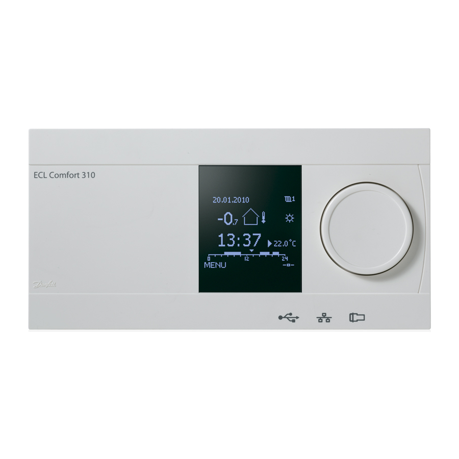
Page 52: Understanding The Controller Display
Operating Guide ECL Comfort 310, application A368 3.2 Understanding the controller display This section describes the function in general for the ECL Comfort 210 / 296 / 310 series. The shown displays are typical and not application related. They might differ from the displays in your application. - Page 53 Operating Guide ECL Comfort 310, application A368 If the temperature value is displayed as "- -" the sensor in question is not connected. "- - -" the sensor connection is short-circuited. DHW circuit Overview display 1: Overview display 2: Overview display 1 informs about: actual DHW temperature, controller mode, desired DHW temperature as well as the comfort schedule of the current day.
- Page 54 Operating Guide ECL Comfort 310, application A368 The setting of the desired room temperature is important even if a room temperature sensor / Remote Control Unit is not connected. Setting the desired DHW temperature The desired DHW temperature can easily be adjusted in the overview displays for the DHW circuit.
-
Page 55: A General Overview: What Do The Symbols Mean
Operating Guide ECL Comfort 310, application A368 3.3 A general overview: What do the symbols mean? Symbol Description Symbol Description Alarm Outdoor temp. Monitoring temperature sensor connection Relative humidity indoor Temperature Display selector Room temp. Max. and min. value DHW temp. - Page 56 Operating Guide ECL Comfort 310, application A368 3.4 Monitoring temperatures and system components Heating circuit The overview display in the heating circuit ensures a quick overview of the actual and (desired) temperatures as well as the actual state of the system components.
-
Page 57: Influence Overview
Operating Guide ECL Comfort 310, application A368 3.5 Influence overview This section describes the function in general for the ECL Comfort 210 / 296 / 310 series. The shown displays are typical and not application related. They might differ from the displays in your application. -
Page 58: Manual Control
Operating Guide ECL Comfort 310, application A368 3.6 Manual control It is possible to manually control the installed components. Manual control can only be selected in favorite displays in which the symbols for the controlled components (valve, pump etc.) are visible. -
Page 59: Schedule
Operating Guide ECL Comfort 310, application A368 3.7 Schedule 3.7.1 Set your schedule This section describes the schedule in general for the ECL Comfort 210 / 296 / 310 series. The shown displays are typical and not application related. They might differ from the displays in your application. -
Page 60: Settings Overview
Operating Guide ECL Comfort 310, application A368 4.0 Settings overview It is recommendable to make a note of any changed settings in the empty columns. Setting Page Factory settings in circuit(s) Heat curve Desired T (Desired flow temperature) 1x004 Temp. min. (duct / flow / inlet temp. limit, min.) 1x177 Temp. - Page 61 Operating Guide ECL Comfort 310, application A368 Setting Page Factory settings in circuit(s) M run (running time of the motorized control valve) 1x186 Nz (neutral zone) 1x187 Min. act. time (min. activation time gear motor) 1x189 P exercise (pump exercise)
- Page 62 Operating Guide ECL Comfort 310, application A368 Setting Page Factory settings in circuit(s) 10657 Alarm time-out Read- State Baud (bits per second) 5997 5998 NONE Command M-bus address 6000 Type 6001 Scan time 6002 60 sec Read- Read- Energy meter 1 (2, 3, 4, 5)
-
Page 63: Settings
Operating Guide ECL Comfort 310, application A368 5.0 Settings 5.1 Introduction to Settings Descriptions of settings (parameter's functions) are divided into groups as used in the ECL Comfort 210 / 296 / 310 controller's menu structure. Examples: "Flow temperature", "Room limit" and so on. -
Page 64: Flow Temperature
Operating Guide ECL Comfort 310, application A368 5.2 Flow temperature Desired flow temperature The ECL Comfort controller determines and controls the flow temperature related to the outdoor temperature. This relationship is called the heat curve. The heat curve is set by means of 6 coordinate points. The desired flow temperature is set at 6 pre-defined outdoor temperature values. - Page 65 Operating Guide ECL Comfort 310, application A368 Choosing a heat curve slope The heat curves represent the desired flow temperature at different outdoor temperatures and at a desired room temperature of 20 °C. 3.0 3.4 The small arrows ( ) indicate 6 different outdoor temperature values at which you can change the heat curve.
- Page 66 Operating Guide ECL Comfort 310, application A368 Parameters indicated with an ID no. like "1x607" mean a universal parameter. x stands for circuit / parameter group. MENU > Settings > Flow temperature MENU > Settings > Tank temperature 1x004 Desired T (Desired flow temperature)
- Page 67 Operating Guide ECL Comfort 310, application A368 A368.2 and A368.4: The max. value is not adjustable, but determined by the settings "High sup. T X2" and related (ID: 1x300, 1x301, 1x302 and 1x303). MENU > Settings > Flow temperature High supp. T X2 (high value of supply temp.)
- Page 68 Operating Guide ECL Comfort 310, application A368 MENU > Settings > Flow temperature 1x303 Low T max Y1 (low value of max limitation) Circuit Setting range Factory setting * See Appendix “Parameter ID overview” Set the low value for the max. limitation of the desired flow temperature.
-
Page 69: Return Limit
Operating Guide ECL Comfort 310, application A368 5.3 Return limit The return temperature limitation is based on the outdoor temperature. Typically in district heating systems a higher return temperature is accepted at a decrease in outdoor temperature. The relationship between the return temperature limits and outdoor temperature is set in two coordinates. - Page 70 Operating Guide ECL Comfort 310, application A368 Example, maximum return temperature limitation; return temperature gets higher than limit = Temperature = Temperature = Time # 1 # = Return temperature # 2 # = Return temperature limit # 3 # = Desired flow temperature # 4 # = Action point Example, minimum return temperature limitation;...
- Page 71 Operating Guide ECL Comfort 310, application A368 Parameters indicated with an ID no. like "1x607" mean a universal parameter. x stands for circuit / parameter group. MENU > Settings > Return limit 1x028 Con.T, re. T lim. (Constant temperature mode, return...
- Page 72 Operating Guide ECL Comfort 310, application A368 MENU > Settings > Return limit 1x031 High T out X1 (return temp. limitation, high limit, X-axis) Circuit Setting range Factory setting Set the outdoor temperature value for the low return temperature limitation.
- Page 73 Operating Guide ECL Comfort 310, application A368 MENU > Settings > Return limit Example The return limit is active above 20 °C. 1x035 Infl. - max. (return temp. limitation - max. influence) The influence is set to 0.5. The actual return temperature is 2 degrees too high.
- Page 74 Operating Guide ECL Comfort 310, application A368 MENU > Settings > Return limit 1x085 Priority (priority for return temp. limitation) If you have a DHW application: Factory setting Circuit Setting range Please also see ‘Parallel operation’ (ID 11043). Choose whether the return temperature limitation should overrule the set min.
-
Page 75: Flow / Power Limit
Operating Guide ECL Comfort 310, application A368 5.4 Flow / power limit Heating circuit A flow or energy meter can be connected (M-bus signal) to the ECL controller in order to limit the flow or consumed power. The flow / power limitation can be based on the outdoor temperature. - Page 76 / parameter group. MENU > Settings > Flow / power limit Input type 1x10⁹ Flow or power limitation is based on M-bus signal (ECL Comfort 310 Circuit Setting range Factory setting controllers only). EM1 ... EM5 / OFF Choice of M-bus signal from energy meter number 1 ...
- Page 77 Operating Guide ECL Comfort 310, application A368 MENU > Settings > Control par., fan MENU > Settings > Flow / power limit 1x111 Limit (limitation value) Circuit Setting range Factory setting This value is in some applications a calculated limitation value, based on the actual outdoor temperature.
- Page 78 Operating Guide ECL Comfort 310, application A368 MENU > Settings > Flow / power limit 1x115 Units List for setting range of 'Units': Factory setting Circuit Setting range See the list l / h m³/h Choice of units for measured values.
- Page 79 Operating Guide ECL Comfort 310, application A368 MENU > Settings > Flow / power limit 1x119 High T out X1 (flow / power limitation, high limit, X-axis) Factory setting Circuit Setting range Set the outdoor temperature value for the low flow / power limitation.
-
Page 80: Optimization
Operating Guide ECL Comfort 310, application A368 5.5 Optimization The section "Optimization" describes specific application related issues. The parameters 'Auto saving', 'Boost', 'Optimizer', 'Total stop' are all related to heating mode only. 'Summer, cut-out' determine, at rising outdoor temperature, the stop of heating. - Page 81 Operating Guide ECL Comfort 310, application A368 MENU > Settings > Optimization 1x011 Auto saving (saving temp. dependent on outdoor temp.) Circuit Setting range Factory setting Below the set value for the outdoor temperature, the saving temperature setting has no influence. Above the set value for the outdoor temperature, the saving temperature relates to the actual outdoor temperature.
- Page 82 Operating Guide ECL Comfort 310, application A368 MENU > Settings > Optimization Boost 1x012 Circuit Setting range Factory setting Shortens the heating-up period by increasing the desired flow temperature by the percentage you set. * See Appendix “Parameter ID overview”...
- Page 83 Operating Guide ECL Comfort 310, application A368 MENU > Settings > Optimization Table I: Optimizer (optimizing time constant) 1x014 System type Left digit Heat accumulation of the building Circuit Setting range Factory setting light Radiator systems medium Optimizes the start and stop times for the comfort temperature period to heavy obtain the best comfort at the lowest energy consumption.
- Page 84 Operating Guide ECL Comfort 310, application A368 MENU > Settings > Application Total stop = OFF MENU > Settings > Optimization Total stop 1x021 Circuit Setting range Factory setting Decide whether you want a total stop during the saving temperature period.
- Page 85 Operating Guide ECL Comfort 310, application A368 MENU > Settings > Optimization 1x043 Parallel operation Circuit Setting range Factory setting Choose whether the heating circuit is to operate in dependence of the DHW circuit. This function might be useful if an installation has limited power or flow.
- Page 86 Operating Guide ECL Comfort 310, application A368 MENU > Settings > Application Total stop = ON MENU > Settings > Heat cut-out MENU > Settings > Optimization 1x179 Summer, cut-out (limit for heating cut-out) Factory setting Circuit Setting range * See Appendix “Parameter ID overview”...
-
Page 87: Control Parameters
Operating Guide ECL Comfort 310, application A368 5.6 Control parameters Control of valves The motorized control valves are controlled by means of 3-point control signal. Valve control: The motorized control valve is opened gradually when the flow temperature is lower than the desired flow temperature and vice versa. - Page 88 Auto tuning is only applicable in connection with valves that are the controller, but it can be activated when needed, e.g. for an approved for auto tuning, i.e. the Danfoss types VB 2 and VM 2 with extra check of the control parameters.
- Page 89 Operating Guide ECL Comfort 310, application A368 MENU > Settings > Boiler MENU > Settings > Control par. MENU > Settings > Control par., cool. MENU > Settings > Control par., fan MENU > Settings > Control par., inlet MENU > Settings > Control par., outlet MENU >...
- Page 90 Operating Guide ECL Comfort 310, application A368 MENU > Settings > Boiler MENU > Settings > Control par. MENU > Settings > Control par., cool. MENU > Settings > Control par., fan The neutral zone is symmetrical around the desired flow / duct MENU >...
- Page 91 Operating Guide ECL Comfort 310, application A368 If you want to tune the PI regulation precisely, you can use the following method: • Set the ‘Tn’ (integration time constant) to its max. value (999 sec.). • Decrease the value for the ‘Xp’ (proportional band) until the system starts hunting (i.e. gets unstable) with a constant amplitude (it might be necessary to force the system by setting an extreme low value).
-
Page 92: Pump Control
Operating Guide ECL Comfort 310, application A368 5.7 Pump control This application can operate with one or two circulation pumps. When operating with two circulation pumps, the pumps are controlled alternately, according to a time set-up. When a pump is switched ON the controller is waiting for differential pressure S7 to build up. - Page 93 Operating Guide ECL Comfort 310, application A368 MENU > Settings > Pump control 1x310 Retry time Factory setting Circuit Setting range If an alarm has been generated for the pump or alarms have been generated for both pumps, this setting will determine the time between the time of the alarm and the retry time for repeated pump start.
- Page 94 Operating Guide ECL Comfort 310, application A368 MENU > Settings > Pump control 1x313 Stab. time (stabilization time) If the chosen stabilization time (‘Stab. time’) is too short, the active Circuit Setting range Factory setting pump will stop immediately after the stabilization time has elapsed.
-
Page 95: Refill Water
Operating Guide ECL Comfort 310, application A368 5.8 Refill water Leaks on the consumers side will result in falling static pressure and thereby a poor supply of heating. A refill water function can inject water to increase the static pressure. - Page 96 Operating Guide ECL Comfort 310, application A368 MENU > Settings > Refill water Pressure Circuit Setting range Factory setting Read-out only The read-out can be a value (in bar): • The pressure is measured by means of a pressure transmitter.
- Page 97 Operating Guide ECL Comfort 310, application A368 MENU > Settings > Refill water 1x320 P exercise (pump exercise) Circuit Setting range Factory setting The time the pump is activated during exercise. Exercise takes place every day (at 12:00). * See Appendix “Parameter ID overview”...
- Page 98 Operating Guide ECL Comfort 310, application A368 MENU > Settings > Refill water 1x323 Time-out Circuit Setting range Factory setting Setting of the max. time for refill. The pressure, measured by S10, must be OK within the set time. If not, the refill water function stops and an alarm is activated.
- Page 99 Operating Guide ECL Comfort 310, application A368 MENU > Settings > Refill water 1x325 Valve delay Circuit Setting range Factory setting Setting of the time for activation of the ON/OFF valve after start of the refill water pump. * See Appendix “Parameter ID overview”...
- Page 100 Operating Guide ECL Comfort 310, application A368 MENU > Settings > Refill water 1x327 Input type When selecting ‘OFF’ , the refill water system could be self-acting. Circuit Setting range Factory setting Choice of pressure input signal. * See Appendix “Parameter ID overview”...
-
Page 101: Application
Operating Guide ECL Comfort 310, application A368 5.9 Application The section "Application" describes specific application related issues. Parameters indicated with an ID no. like "1x607" mean a universal parameter. x stands for circuit / parameter group. MENU > Settings > Application... - Page 102 Operating Guide ECL Comfort 310, application A368 MENU > Settings > Application 1x023 M exercise (valve exercise) Circuit Setting range Factory setting Exercises the valve to avoid blocking in periods without heat demand. * See Appendix “Parameter ID overview” OFF: The valve exercise is not active.
- Page 103 Operating Guide ECL Comfort 310, application A368 MENU > Settings > Application 1x078 P heat T (heat demand) The valve is fully closed as long as the pump is not switched on. Circuit Setting range Factory setting When the desired flow temperature is above the set temperature in ‘P heat T’ , the controller automatically switches ON the circulation pump.
- Page 104 Operating Guide ECL Comfort 310, application A368 Override mode functions: Example: Connection of an override switch The following settings describe the function in general for the ECL Comfort 210 / 296 / 310 series. The explained modes are typical and not application related. They might differ from the override modes in your application.
- Page 105 Operating Guide ECL Comfort 310, application A368 MENU > Settings > Application 1x142 Ext. mode (external override mode) See also ‘Ext. input’ . Circuit Setting range Factory setting COMFORT / SAVING / COMFORT Example: Override to Comfort mode FROST PR. / CONST. T The mode override can be activated for Saving, Comfort, Frost pr.
- Page 106 Operating Guide ECL Comfort 310, application A368 Example: Override to Frost protection mode # 1 # = Override switch (not activated / activated) # 2 # = Function mode (Schedule / Frost pr.) # 3 # = Time Example: Override to Constant temperature mode # 1 # = Override switch (not activated / activated) # 2 # = Function mode (Schedule / Const.
- Page 107 Operating Guide ECL Comfort 310, application A368 MENU > Settings > Application 1x500 Send desired T In the master controller, 'Demand offset' must be set to a value in order Circuit Setting range Factory setting to react on a desired flow temperature from a slave controller.
-
Page 108: Heat Cut-Out
Operating Guide ECL Comfort 310, application A368 5.10 Heat cut-out MENU > Settings > Heat cut-out The setting “Summer cut-out” under “Optimization” for the heating circuit in question determines a heating cut-out when the outdoor temperature exceeds the set value. - Page 109 Operating Guide ECL Comfort 310, application A368 5.10.1 Differentiated heat cut-out To set differentiated cut-out parameters for a heating circuit for “Summer” and “Winter” go to “Heat cut-out”: (MENU > Settings > Heat cut-out) This function is active when the dates for “Summer” and “Winter”...
- Page 110 Operating Guide ECL Comfort 310, application A368 5.10.2 Summer/winter filter constant The filter constant of 250 is applicable for average buildings. A filter constant of 1 is close switching according to actual outdoor temperature meaning low filtering (very “light” building).
-
Page 111: Water Meter
Operating Guide ECL Comfort 310, application A368 5.11 Water meter Application A368.5 A water meter, F1, can measure the amount of refill water injected into the heating installation. The water flow at F1 is measured by means of: a flow meter, giving pulses to "Pulse 1" on the ECA 32... - Page 112 Operating Guide ECL Comfort 310, application A368 MENU > Settings > Water meter Preset 1x514 Circuit Setting range Factory setting Is used for resetting the measured water consumption (registered by the water meter). Via the Modbus communication a value can be preset to a defined value, for example if the water meter is replaced.
-
Page 113: Alarm
Operating Guide ECL Comfort 310, application A368 5.12 Alarm The section "Alarm" describes specific application related issues. Application A368 offers different types of alarms: Type Description: Actual flow temperature differs from the desired flow temperature Activation of alarm input(s) S9 / (S12) - Page 114 Operating Guide ECL Comfort 310, application A368 Alarm overview, list Alarm Description: Alarm Sensor A368.1 A368.3 A368.6 ref.: A368.2 A368.4 no.: type: A368.5 Refill water Pump 1 Pump 2 Pump 3 Pump 5 Temp. monitor, heating Temp. monitor, DHW Digital 9...
- Page 115 Operating Guide ECL Comfort 310, application A368 MENU > Alarm > Charge T Upper difference MENU > Alarm > Temp. monitor MENU > Event > Charge T MENU > Event > Tank temp. 1x147 Upper difference Circuit Setting range Factory setting...
- Page 116 Operating Guide ECL Comfort 310, application A368 MENU > Alarm > Charge T MENU > Alarm > Temp. monitor 1x150 Lowest temp. If the cause of the alarm disappears, the alarm indication and output also disappear. Circuit Setting range Factory setting The alarm function will not be activated if the desired flow / duct temperature is lower than the set value.
-
Page 117: Alarm Overview
Operating Guide ECL Comfort 310, application A368 5.13 Alarm overview MENU > Alarm > Alarm overview This menu shows the alarm types, for example: Resetting an alarm, in general: • "2: Temp. monitor" MENU > Alarm > Alarm overview: •... -
Page 118: Anti-Bacteria
Operating Guide ECL Comfort 310, application A368 5.14 Anti-bacteria On selected days during the week the DHW temperature can be increased in order to neutralize bacteria in the DHW system. The desired DHW temperature 'Desired T' (typically 80 °C) will be present for the selected day(s) and duration. -
Page 119: Danfoss District Energy
Operating Guide ECL Comfort 310, application A368 MENU > Settings > Anti-bacteria Start time Circuit Setting range Factory setting 00:00 ... 23:30 00:00 Set the start time for the anti-bacteria function. MENU > Settings > Anti-bacteria Duration Factory setting Circuit Setting range 10 ... -
Page 120: Common Controller Settings
Operating Guide ECL Comfort 310, application A368 6.0 Common controller settings 6.1 Introduction to ‘Common controller settings’ Some general settings which apply to the entire controller are Circuit selector located in a specific part of the controller. To enter ‘Common controller settings’:... -
Page 121: Time & Date
Operating Guide ECL Comfort 310, application A368 6.2 Time & Date It is only necessary to set the correct date and time in connection with the first use of the ECL Comfort controller or after a power break of more than 72 hours. -
Page 122: Settings
Operating Guide ECL Comfort 310, application A368 6.3 Settings Pressure measuring S11 S12 S13 S14 S15 S16 A368.1 A368.2 A368.3 ✔ ✔ ✔ ✔ ✔ ✔ ✔ ✔ ✔ ✔ ✔ ✔ ✔ ✔ ✔ A368.4 ✔ ✔ ✔ ✔ ✔ ✔... -
Page 123: Holiday
Operating Guide ECL Comfort 310, application A368 6.4 Holiday This section describes the function in general for the ECL Comfort 210 / 296 / 310 series. The shown displays are typical and not application related. They might differ from the displays in your application. - Page 124 Operating Guide ECL Comfort 310, application A368 Holiday, specific circuit / Common Controller Example 1: When setting one holiday program in specific circuit and another Circuit 1: holiday program in Common Controller, a priority will be taken Holiday set to "Saving"...
-
Page 125: Input Overview
Operating Guide ECL Comfort 310, application A368 6.5 Input overview This section describes the function in general for the ECL Comfort 210 / 296 / 310 series. The shown displays are typical and not application related. They might differ from the displays in your application. -
Page 126: Log
Operating Guide ECL Comfort 310, application A368 6.6 Log This section describes the function in general for the ECL Comfort 210 / 296 / 310 series. The shown displays are typical and not application related. They might differ from the displays in your application. -
Page 127: Output Override
Operating Guide ECL Comfort 310, application A368 6.7 Output override This section describes the function in general for the ECL Comfort 210 / 296 / 310 series. The shown displays are typical and not application related. They might differ from the displays in your application. -
Page 128: Alarm
Operating Guide ECL Comfort 310, application A368 6.8 Alarm 6.8.1 Digital S9 / S12 Alarm inputs A368.1 ✔ ✔ ✔ A368.2 ✔ ✔ ✔ A368.3 ✔ ✔ ✔ ✔ ✔ ✔ A368.4 ✔ ✔ ✔ ✔ ✔ ✔ A368.5 ✔ ✔ ✔... -
Page 129: Key Functions
Operating Guide ECL Comfort 310, application A368 6.9 Key functions New application Erase application: Removes the existing application. As soon as the ECL key is inserted, another application can be chosen. Application Gives an overview over the actual application in the ECL controller. Push the dial again to exit the overview. -
Page 130: System
An example could be the ECA 32 module. 6.10.3 Ethernet The ECL Comfort 310 (only) has a Modbus/TCP communication interface that allows the ECL controller to be connected to an Ethernet network. This allows remote access to the ECL 310 controller based on standard communication infrastructures. - Page 131 Circuit Setting range Factory setting If ECL Comfort 310 is connected to the ECL Portal, a baud rate of 2400 is recommendable, provided the energy meter allows this. 300 / 600 / 1200 / 2400 The communication speed between ECL Comfort 310 and the connected energy meter(s).
- Page 132 When all energy meters are found, the command can be changed to INIT or NONE. NONE / INIT / SCAN / GATEW NONE The ECL Comfort 310 is M-bus master. In order to verify connected energy meters, different commands can be activated. NONE: No command activated...
- Page 133 Operating Guide ECL Comfort 310, application A368 MENU > Common controller > System > M-bus config. Scan time 6002 Energy meter 1 (2, 3, 4, 5) If the energy meter is battery powered, the scan time should be set to a high value to prevent a too fast battery draining.
- Page 134 Operating Guide ECL Comfort 310, application A368 6.10.7 Display 60058 Backlight (display brightness) Circuit Setting range Factory setting 0 ... 10 Adjust the brightness of the display. Weak backlight. Strong backlight. Contrast (display contrast) 60059 Circuit Setting range Factory setting 0 ...
- Page 135 Operating Guide ECL Comfort 310, application A368 2048 ECL 485 addr. (master / slave address) Circuit Setting range Factory setting The total cable length of max. 200 m (all devices incl. the internal ECL 0 ... 15 485 communication bus) should not be exceeded.
- Page 136 Operating Guide ECL Comfort 310, application A368 6.10.9 Language Language 2050 Circuit Setting range Factory setting Local language is selected during installation. If you want to change to English / ‘Local’ English another local language, the application must be reinstalled. However, it is always possible to change between the local language and English.
-
Page 137: Miscellaneous
Operating Guide ECL Comfort 310, application A368 7.0 Miscellaneous 7.1 ECA 30 / 31 setup procedures ECA 30 (code no. 087H3200) is a remote control unit with built-in room temperature sensor. ECA 31 (code no. 087H3201) is a remote control unit with built-in room temperature sensor and humidity sensor (relative humidity). - Page 138 Operating Guide ECL Comfort 310, application A368 The ECL menus are as described for the ECL controller. Most of the settings done directly in the ECL controller can be done via the ECA 30 / 31 too. All settings can be seen even if the application key is not inserted in the ECL controller.
- Page 139 Operating Guide ECL Comfort 310, application A368 When ECA 30 / 31 is in ECA MENU mode, the date and measured room temperature is displayed. ECA MENU > ECA settings > ECA sensor Room T Offset Example: Setting range Factory setting 0.0 K...
- Page 140 Operating Guide ECL Comfort 310, application A368 ECA MENU > ECA system > ECA display Contrast (display contrast) Setting range Factory setting 0 ... 10 Adjust the contrast of the display. Low contrast. High contrast. ECA MENU > ECA system > ECA display...
- Page 141 Operating Guide ECL Comfort 310, application A368 ECA MENU > ECA system > ECA communication Connection addr. (Connection address) Setting range Factory setting An ECA 30 / 31 can in an ECL 485 bus system (master – slave) be set to 1 …...
- Page 142 Operating Guide ECL Comfort 310, application A368 ECA MENU > ECA system > ECA override Override circuit Setting range Factory setting OFF / 1 … 4 The circuit in question for override in the ECL controller must be in scheduled mode.
- Page 143 Operating Guide ECL Comfort 310, application A368 ECA MENU > ECA factory > ECA clear apps. Erase all apps. (Erase all applications) Erase all applications which are in the ECA 30 / 31. After erasing, the application can be uploaded again.
- Page 144 Operating Guide ECL Comfort 310, application A368 ECA MENU > ECA factory > Reset ECL addr. Reset ECL addr. (Reset ECL address) If none of the connected ECL Comfort controllers has the address 15, the ECA 30 / 31 can set all connected ECL controllers on the The ECL 485 bus related address of the ECL controller is found: ECL 485 bus back to address 15.
-
Page 145: Override Function
Operating Guide ECL Comfort 310, application A368 7.2 Override function Example, override switch connected to S8: The ECL 210 / 296 / 310 controllers can receive a signal in order to override the existing schedule. The override signal can be a switch or a relay contact. - Page 146 Operating Guide ECL Comfort 310, application A368 Example 2 ECL in Comfort mode, but in Saving mode at override. Choose an unused input, for example S8. Connect the override switch or override relay contact. Settings in ECL: 1. Select circuit > MENU > Settings > Application > Ext. input: Select the input S8 (the wiring example) 2.
- Page 147 Operating Guide ECL Comfort 310, application A368 Example 4 The week schedule for the building is set with comfort periods all weekdays: 06.00 - 20.00. Sometimes, the desired flow temperature must be constant on 65 °C. An override relay is installed and the flow temperature must be 65 °C as long as the override relay is activated.
-
Page 148: Several Controllers In The Same System
Operating Guide ECL Comfort 310, application A368 7.3 Several controllers in the same system When ECL Comfort controllers are interconnected by means of the ECL 485 communication bus (cable type: 2 x twisted pair), the master controller will broadcast the following signals to the slave controllers: •... - Page 149 Operating Guide ECL Comfort 310, application A368 Situation 2: SLAVE controller: How to react on a DHW tank heating / charging activity sent from the MASTER controller The slave receives information about a DHW tank heating / charging activity in the master controller and can be set to close the selected heating circuit.
- Page 150 Operating Guide ECL Comfort 310, application A368 Situation 3: SLAVE controller: How to make use of the outdoor temperature signal and send information about the desired flow In the MASTER controller, the address in ‘ECL 485 addr. (master / slave temperature back to the MASTER controller address)’...
-
Page 151: Frequently Asked Questions
'Common controller settings' >'Key functions' > 'Application'. The system type (e.g. TYPE A266.1) and the system diagram is displayed. Order a replacement from your Danfoss representative (e.g. ECL Application Key A266). Insert the new ECL Application Key and copy your personal settings from the controller to the new ECL Application Key, if required. - Page 152 Operating Guide ECL Comfort 310, application A368 Why can’t an application be selected when inserting the ECL application key into the controller? The actual application in the ECL Comfort controller must be deleted before a new application (subtype) can be selected.
- Page 153 Operating Guide ECL Comfort 310, application A368 How to set a correct heat curve? Short answer: 3.0 3.4 Set the heat curve to the lowest possible value, but still having comfortable room temperature. The table shows some recommendations: House with Needed flow temp.
-
Page 154: Definitions
Operating Guide ECL Comfort 310, application A368 7.5 Definitions The definitions apply to the ECL Comfort 210 / 296 / 310 series. Consequently, you might come across expressions that are not mentioned in your guide. Accumulated temperature value A filtered (dampened) value, typically for room and outdoor temperatures. - Page 155 Operating Guide ECL Comfort 310, application A368 DHW circuit The circuit for heating the domestic hot water (DHW). Duct temperature Temperature measured in the air duct where the temperature is to be controlled. ECL Portal A supervisory system for remote control and monitoring, locally and via Internet.
- Page 156 Operating Guide ECL Comfort 310, application A368 Outdoor temperature trend The arrow indicates the tendency, i.e. whether the temperature rises or falls. Override mode When ECL Comfort is in Scheduled mode, a switch or contact signal can be applied to an input in order to override to Comfort, Saving, Frost protection or Constant temperature.
-
Page 157: Type (Id 6001), Overview
Operating Guide ECL Comfort 310, application A368 7.6 Type (ID 6001), overview Type 0 Type 1 Type 2 Type 3 Type 4 Address ✔ ✔ ✔ ✔ ✔ Type ✔ ✔ ✔ ✔ ✔ Scan time ✔ ✔ ✔ ✔... -
Page 158: Parameter Id Overview
Operating Guide ECL Comfort 310, application A368 7.7 Parameter ID overview A368.x — x refers to the subtypes listed in the column. A368.x Factory Parameter Name Setting range Unit Own settings 10609 Low Y 3, 4, 5 0.0 ... 30.0... - Page 159 Operating Guide ECL Comfort 310, application A368 Parameter Name A368.x Setting range Factory Unit Own settings 11115 Units 1, 2, 3, 4, 5, 6 ml, l/h ; l, l/h ml, l/h ; ml, m3/h ; l, m3/h ; Wh, kW ; kWh, kW ;...
- Page 160 Operating Guide ECL Comfort 310, application A368 Parameter Name A368.x Setting range Factory Unit Own settings 11315 Circ. pumps 1, 2, 3, 4, 5, 6 OFF ; ON 11316 Alarm handling 1, 2, 3, 4, 5, 6 OFF ; ON...
- Page 161 Operating Guide ECL Comfort 310, application A368 Parameter Name A368.x Setting range Factory Unit Own settings 12113 Filter constant 1, 2, 3, 4, 5, 6 1 ... 50 12115 Units 1, 2, 3, 4, 5, 6 ml, l/h ; l, l/h ml, l/h ;...
- Page 162 Operating Guide ECL Comfort 310, application A368 Installer: Date: Danfoss District Energy DEN-SMT/DK VI.LG.J3.02...
-
Page 163: Vilgj302
Operating Guide ECL Comfort 310, application A368 *087H9018* *VILGJ302* Produced by Danfoss A/S © 03/2016...