
Subscribe to Our Youtube Channel
Related Manuals for Clarke CLS405


Summary of Contents for Clarke CLS405
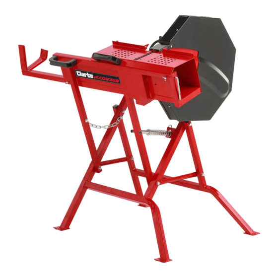
- Page 1 405MM CIRCULAR LOGSAW MODEL NO: CLS405 PART NO: 3401997 ASSEMBLY & OPERATING INSTRUCTIONS ORIGINAL INSTRUCTIONS GC1120 - ISS 1...
- Page 2 When unpacking, check for damage or shortages etc. Any found should be reported to your CLARKE dealer where the product was originally purchased. Please keep these instructions in a safe place for future reference.
-
Page 3: Specifications
SPECIFICATIONS Model Number CLS405 Cutting Length Min/max 250 -1000 mm Cutting Capacity (min/max dia) 30 - 140 mm Wood Weight Max 11 kg Operating Voltage 230V / 50Hz Motor Power 2200 W IP Rating IP54 No load blade Speed 2800 rpm... -
Page 4: Safety Warnings
SAFETY WARNINGS WORK AREA 1. Keep the work area clean and well lit. Cluttered and dark areas invite accidents. 2. DO NOT operate power tools in explosive atmospheres such as in the presence of flammable liquids, gasses or dust. Power tools create sparks which may ignite dust or fumes. - Page 5 3. DO NOT over-reach. Keep your proper footing and balance at all times. This enables better control of the power tool in unexpected situations. 4. Concentrate on the job in hand, no matter how trivial it may seem. Be aware that accidents are caused by carelessness due to familiarity. 5.
-
Page 6: Precautions Specific To Circular Saws
Ensure the blade is secure before use. 2. Use the appropriate saw blade for this saw. Correct blades are available from your CLARKE dealer Part No 3401991 3. ONLY use saw blades in good working condition. Discard and replace cracked or bent saw blades. -
Page 7: Safety Symbols & Pictograms
SAFETY SYMBOLS & PICTOGRAMS Please read all of the safety and operating instructions carefully before using this product. The following safety symbols are found on the product. Refer to instruction Never reach into the manual before use. running saw blade. Wear eye protection Wear a breathing mask Wear ear protection... -
Page 8: Electrical Connections
ELECTRICAL CONNECTIONS WARNING: READ THESE ELECTRICAL SAFETY INSTRUCTIONS THOROUGHLY BEFORE CONNECTING THE PRODUCT TO THE MAINS SUPPLY. Connect the mains lead to a standard, 230 Volt (50Hz) electrical supply through an approved 13 amp BS1363 plug, or a suitably fused isolator switch. If the plug has to be changed because it is not suitable for your socket or because of damage, it must be removed and a replacement fitted, following the wiring instructions shown below. - Page 9 INVENTORY Motor Saw Blade Base Frame Limit Plate Log Carriage Extension Handle Pivoting Log Carriage Top Guard Inner Saw Blade Cover Back Plate 1 Blade Guard 2 Back Plate 2 Outer Saw Blade Cover Guide Tube with Return Spring Blade Guard Cross Brace Front Clamping Disc Blade Wrench, Face Wrench, Spanner...
- Page 10 ASSEMBLY This log saw was partially assembled at the factory. To complete your saw follow the instructions below. SAW BLADE GUARDS 1. Place the back plate 1, against the outside of the connecting part of the log carriage and align its two holes with the upper two holes of the connecting part as Fig step 1.
-
Page 11: On/Off Switch
HANDLE Attach the handle to the back of the log carriage. Secure it with two M8x25 bolts and lock nuts as Fig B. Screw the wing bolt M5 x 20 into the hole at the upper right corner. ON/OFF SWITCH Fix the switch to the motor plate with two M4 x 55 bolts as Fig C. -
Page 12: Return Spring
RETURN SPRING Fix one end of the guide pipe with return spring on the left leg with M8 x 55 bolts, washers and lock nut as Fig D. CONNECTING PIVOTING LOG CARRIAGE AND BASE FRAME Lay the pivoting log carriage on the ground with legs inside the base frame, and put one end of the cross brace outside as shown... -
Page 13: Saw Blade
INNER SAW BLADE COVER Slide the shaft through the centre hole of the inner saw blade cover and align its other holes with those on the motor plate as Fig F. Secure it with three M8 x 20 bolts, washers and lock nuts on the upper side and one M8 x 45 bolt, washer and lock nut on the lower. - Page 14 IMPORTANT: Keep the two special wrenches in a safe place. CAUTION: INSTALLING THE BLADE THE WRONG WAY ROUND WILL RESULT IN DAMAGE TO THE BLADE. THE ARROW MUST POINT TOWARDS THE DIRECTION OF ROTATION. OUTER SAW BLADE COVER Tighten the outer saw blade cover to the inner cover with four M5 x 10 cross head screws and flat washers as Fig H.
- Page 15 FIXING RETURN SPRING/CHAIN AND GUARD PLATE Take the cotter pin and washer from the guiding pipe with spring as Fig I step 1. Push the log carriage to the base frame until the open end of the guiding pipe is inserted into the angle part of the base frame as Fig I step 2.
- Page 16 LIMIT PLATE Mount the limit plate and fasten with two M5 x 10 screws, washers and spring washers as in Fig J. TOP GUARD Mount the top guard with four M5 x 10 bolts and locknuts as Fig K. Parts & Service: 020 8988 7400 / E-mail: Parts@clarkeinternational.com or Service@clarkeinternational.com...
- Page 17 LOG CARRIAGE EXTENSION Loosen the wing bolt M5 x 20 on the back of the log carriage until the carriage extension can be inserted into the opening. Slide the carriage extension into the channel and align it correctly. Secure it with the wing bolt. MOUNTING THE SAW TO THE FLOOR The foot of each leg is provided with an 8mm bolt hole for fixing...
-
Page 18: Operation
OPERATION 1. Check that all component parts are secure. If the log saw is not fixed to the floor, ensure that it is placed in a steady position on firm ground. 2. Ensure the power cable is well away from the saw and the workpiece, then plug into the mains supply. -
Page 19: Maintenance
If using compressed air always wear goggles and a dust mask. 6. For any problems requiring the dismantling and overhaul of the saw, contact your CLARKE International Service Department on 020-8988-7400. STORAGE 1. Store in a clean, dry environment protected from the weather and away from children and untrained users. -
Page 20: Saw Blade Change
SAW BLADE CHANGE 2. Remove the limit plate by unfastening the M5 x 10 screws and washers. 3. Support the carriage and pull the cotter pin and washer from the return guide tube. 4. Remove the M8 x 50 bolt, washers and nut securing the chain. - Page 21 5. Lower the log carriage towards the ground. 6. Remove the four M5 x 10 screws and washers from the blade guard and from the outer blade cover. Parts & Service: 020 8988 7400 / E-mail: Parts@clarkeinternational.com or Service@clarkeinternational.com...
-
Page 22: Sharpening The Blade
Check the blade carefully for cracks NOTE: Replacement blades are available from your CLARKE dealer as Part No 3401991. Parts & Service: 020 8988 7400 / E-mail: Parts@clarkeinternational.com or Service@clarkeinternational.com... -
Page 23: Fault Finding
Cause Solution Machine will not No power supply. Check supply and rectify. operate. Switch is faulty. Consult your CLARKE dealer. Fuse in plug has blown. Check and replace. Motor is faulty. Consult your CLARKE dealer. Motor becomes Unduly heavy use. -
Page 24: Parts List
PARTS LIST Description Description Screw M5 x 10 Saw blade guard 2 Washer 5mm Bolt M8 x 55 Flat washer 5mm Flat washer Inner saw blade cover Return spring Outer saw blade cover Bolt M8 x 70 Switch Base frame 2 Motor Cross brace Rear Retaining disc... -
Page 25: Component Parts
COMPONENT PARTS Parts & Service: 020 8988 7400 / E-mail: Parts@clarkeinternational.com or Service@clarkeinternational.com... -
Page 26: Environmental Recycling Policy
GUARANTEE This product is guaranteed against faulty manufacture for a period of 12 months from the date of purchase. Please keep your receipt which will be required as proof of purchase. This guarantee is invalid if the product is found to have been abused or tampered with in any way, or not used for the purpose for which it was intended. -
Page 27: Declaration Of Conformity
DECLARATION OF CONFORMITY Parts & Service: 020 8988 7400 / E-mail: Parts@clarkeinternational.com or Service@clarkeinternational.com...
Need help?
Do you have a question about the CLS405 and is the answer not in the manual?
Questions and answers