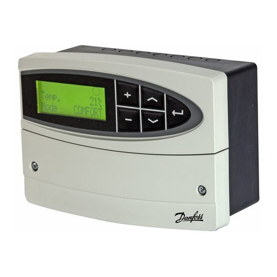
Danfoss ECL Comfort 110 Operating Manual
Hide thumbs
Also See for ECL Comfort 110:
- Operating manual (52 pages) ,
- User manual, installation & maintenance (26 pages) ,
- Datasheet (8 pages)

Related Manuals for Danfoss ECL Comfort 110


Summary of Contents for Danfoss ECL Comfort 110
- Page 1 Operating Guide ECL Comfort 110, application 131 (valid as of software version 2.00) English version www.danfoss.com...
- Page 2 The warning sign is used to emphasize special conditions that should be taken into consideration. This symbol indicates that this particular piece of information should be read with special attention. 2 | © Danfoss | 2016.05 VI.LV.A1.02...
-
Page 3: Table Of Contents
Return T limit (return temp. limitation) 6000 Limit (return temperature limitation value) 6030 Gain - max. (return temp. limitation, maximum) 6035 Gain - min. (return temp. limitation, minimum) 6036 Intgr. time (Integration time) 6037 VI.LV.A1.02 © Danfoss | 2016.05 | 3... - Page 4 Electrical connections - 230 V a.c. - in general Connecting the temperature sensors and the ECL BUS External override How to identify your system type Adapting the ECL Comfort 110 controller Manual control Placing the temperature sensors Checklist, electrical connections...
-
Page 5: Introduction
• Daily use (end user). Setting the desired flow temperature, mode and schedule • Maintenance (installer’s level). Setting of, for example, control functions. Access to Maintenance (installer’s level) on the ECL Comfort 110: Press and hold “Arrow-down” button for 3 sec. -
Page 6: Settings Overview
Control param. – Xp 7184 80 K Control param. – Tn 7185 30 s Control param. – M1 run 7186 96 s Control param. – Nz 7187 Control param. – Min. on time 7189 6 | © Danfoss | 2016.05 VI.LV.A1.02... - Page 7 Application – Type 8600 Service – Code no. 9300 087B1670 Service – Ver. 9301 D200010516 Service – Backlight 9310 Service – Contrast 9311 Service – Language 9315 ENGLISH Service – MOD address 9320 VI.LV.A1.02 © Danfoss | 2016.05 | 7...
-
Page 8: Daily Use
Actual room temperature Desired room temperature S2 des. T S3 act. T Actual flow temperature S3 des. T Desired flow temperature S4 act. T Actual return temperature S4 lim. T Desired return temperature limitation 8 | © Danfoss | 2016.05 VI.LV.A1.02... -
Page 9: Select Control Mode
COMFORT< Wednesday Change the mode (AUTO, COMFORT, SAVING, or STANDBY). Set your personal schedule It is only possible to set the personal schedules if the ECL Comfort 110 controller has a built-in ECA 110 timer program. Wednesday < 04-01-12 8:32 This display will show the current day and time. - Page 10 The schedule has always two comfort periods a day. The start and stop times can be set in half-hourly intervals (30 min.). To arrange only one comfort period on a day: Set Start2 and Stop2 times to the same time value. 10 | © Danfoss | 2016.05 VI.LV.A1.02...
-
Page 11: Maintenance
It is only necessary to set the correct date and time in connection with the first use of the ECL Comfort 110 controller or after a power break of more than 36 hours (see the chapter on Adapting the ECL Comfort 110 controller). -
Page 12: Room T Limit (Room Temperature Limitation) 3000
This section is a general description for Room temperature limitation and is only relevant if you have installed a room temperature sensor (S2). The ECL Comfort 110 adjusts the desired flow temperature to compensate for the difference between the desired and the actual room temperature. -
Page 13: Comfort T (Desired Room Temperature In Comfort Mode) 3180
The “Intgr. time” function can correct the desired flow temperature with max. 8 degrees. OFF: The control function is not influenced by the ‘Intgr. time’. Minor value: The desired room temperature is adapted quickly. Major value: The desired room temperature is adapted slowly. VI.LV.A1.02 © Danfoss | 2016.05 | 13... - Page 14 The actual room temperature is 2 degrees too high. The ‘Gain - max.’ is set to -3.5. The ‘Gain - min.’ is set to 2.0. Result: The desired flow temperature is changed by 2 x (-3.5) = -7.0 degrees. 14 | © Danfoss | 2016.05 VI.LV.A1.02...
-
Page 15: Compensation 1 And 2 4000
The example shows that the desired flow temperature can be influenced when the compensation temperature gets below “Compensation temperature value 1”. Also, the desired flow temperature can be influenced when the compensation temperature gets above “Compensation temperature value 2”. VI.LV.A1.02 © Danfoss | 2016.05 | 15... -
Page 16: Temp. (Compensation Temperature) 4060
Setting the compensation temperature value 1. When the temperature, measured by S1, falls below or gets higher than the set compensation value, the ECL Comfort 110 changes the desired flow temperature. The influence is set in ‘Gain - max.’ and ‘Gain - min.’. -
Page 17: Compensation 2 5000
Setting the compensation temperature value 2. When the temperature, measured by S1, falls below or gets higher than the set compensation value, the ECL Comfort 110 changes the desired flow temperature. The influence is set in ‘Gain - max.’ and ‘Gain - min.’. -
Page 18: Intgr. Time (Integration Time) 5065
‘Gain. min.’ (4063) is set to 2.5. The actual compensation temperature is 2°C (3 degrees below the limit value). Result: The desired flow temperature is changed by 2.5 x 3 = 7.5 degrees. 18 | © Danfoss | 2016.05 VI.LV.A1.02... -
Page 19: Return T Limit (Return Temp. Limitation) 6000
This section is a general description for Return temperature limitation and is only relevant if you have installed a return temperature sensor (S4). The ECL Comfort 110 adjusts the desired flow temperature to compensate for the difference between the limitation temperature and the actual return temperature. -
Page 20: Limit (Return Temperature Limitation Value) 6030
Minor value: The desired flow temperature is changed quickly. Major value: The desired flow temperature is changed slowly. If the ‘Gain’ is too high and / or the ‘Intgr. time’ too low, there is a risk of unstable control. 20 | © Danfoss | 2016.05 VI.LV.A1.02... - Page 21 The desired flow temperature is changed by 2.5 x 3 = 7.5 degrees. Temperature Temperature Time # 1 # Return temperature limit # 2 # Return temperature # 3 # Desired flow temperature # 4 # Action point VI.LV.A1.02 © Danfoss | 2016.05 | 21...
-
Page 22: Control Param. (Control Parameters) 7000
5.0 mm x 15 sec. / mm = 75 sec. Rotating valves Running time = Turning degrees x actuator speed (sec. / degr.) Example: 90 degr. x 2 sec. / degr. = 180 sec. 22 | © Danfoss | 2016.05 VI.LV.A1.02... -
Page 23: Nz (Neutral Zone) 7187
The setting should be kept as high as acceptable to increase the lifetime of the valve actuator. Setting examples Set value x 20 ms 40 ms (= 0.04 sec) 200 ms (= 0.2 sec) 1000 ms (= 1 sec) VI.LV.A1.02 © Danfoss | 2016.05 | 23... - Page 24 ‘Tn’ = 0.85 x critical time period ‘Xp’ = 2.2 x proportional band value in the critical time period. If the regulation seems to be too slow, you can decrease the proportional band value by 10%. 24 | © Danfoss | 2016.05 VI.LV.A1.02...
-
Page 25: Application 8000
Desired flow temperature # 1 # Standby temperature # 2 # Saving temperature # 3 # Desired saving temperature # 4 # Comfort temperature # 5 # Comfort period # 6 # Saving period VI.LV.A1.02 © Danfoss | 2016.05 | 25... -
Page 26: P1 Exercise 8022
Exercises the control valve to avoid blocking in periods without cooling demand. The valve exercise is not active. The valve is opened daily for 15 minutes as from 12.00. The valve is closed as from 12.15. 26 | © Danfoss | 2016.05 VI.LV.A1.02... -
Page 27: P1 Start T (Cooling Demand) 8078
Setting range OFF / Comfort / Saving By means of a switch or a relay contact the ECL Comfort 110 can be overridden to ‘Comfort’ or ‘Saving’ mode. The override switch or relay contact is connected to the input terminals 11 and 12. When closing the switch / relay contacts, the override is activated. -
Page 28: Daylight (Daylight Saving Time Changeover) 8198
Setting range 0 . . . 15 This setting is relevant if more ECL Comfort 110 are connected in the same ECL Comfort system (connected via the ECL BUS). The ECL Comfort 110, which is physically connected with the S1 temperature sensor, must be the master of the entire system and must have the address 15. -
Page 29: Type (Application Type) 8600
Press and hold for 5 sec. Hereafter the ECL Comfort 110 resets. An ECL Comfort 110, new from factory, will show “???” at start-up. Select application 131 by means of the + button. Press and hold the “arrow-down” button for 5 sec. -
Page 30: Service 9000
Maintenance Service 9000 Code no. 9300 Information about the ECL Comfort 110’s code number. Example: 087B1670 Ver. (version no.) 9301 Info ABBBCCWWYY Information about the ECL Comfort 110’s version. = Hardware version BBB = Software version CC = Application version... -
Page 31: Language 9315
Language 9315 Setting range ENGLISH / DANSK Choose the preferred language. MOD address (MODBUS address) 9320 Setting range 0 . . . 250 The MODBUS related functionality is used for production test only. VI.LV.A1.02 © Danfoss | 2016.05 | 31... -
Page 32: Installation
93 x 139 mm. Insert the controller into the panel cut-out and fix it with the clamp which is placed horisontally on the controller. Establish the electrical connections. For further details on mounting, see the mounting guide. 32 | © Danfoss | 2016.05 VI.LV.A1.02... -
Page 33: Electrical Connections - 230 V A.c. - In General
Not to be used Not to be used *: Ohmic load: 4 Amp.; Inductive load: 2 Amp. Wire cross section: 0.5 - 1.5 mm Incorrect connection can damage the TRIAC outputs (terminals 23, 24 and 25). VI.LV.A1.02 © Danfoss | 2016.05 | 33... -
Page 34: Connecting The Temperature Sensors And The Ecl Bus
Cable lengths of more than 125 m may cause noise sensibility (EMC). External override ECL 110 11 12 # 1 # # 2 # Override by means of a relay (# 1 #) or a switch (# 2 #). 34 | © Danfoss | 2016.05 VI.LV.A1.02... -
Page 35: How To Identify Your System Type
Installation How to identify your system type The ECL Comfort 110 is a universal controller that can be used for various systems. Based on the shown standard systems, it is possible to configure additional systems. Cooling system with heat exchanger... -
Page 36: Adapting The Ecl Comfort 110 Controller
Installation Adapting the ECL Comfort 110 controller When you switch on the controller the first time, it will ask you to choose language (default language is English). Language English Choose your language. Options: English and Dansk (Danish). Accept and go to the next menu. - Page 37 Installation If the application 131 has already been chosen, the display shows: Application Type Go to the ‘Maintenance’ part for further setup of your controller. VI.LV.A1.02 © Danfoss | 2016.05 | 37...
-
Page 38: Manual Control
Manual mode Pump P1 is OFF ( Pump Select control mode. Mode MANUAL< Wednesday Manual mode should only be used for maintenance purposes. In manual mode all control and safety functions are deactivated! 38 | © Danfoss | 2016.05 VI.LV.A1.02... -
Page 39: Placing The Temperature Sensors
Place the sensor max. 15 cm from the mixing point. In systems with heat exchanger, Danfoss recommends that the ESMU-type to be inserted into the exchanger flow outlet. Make sure that the surface of the pipe is clean and even where the sensor is mounted. -
Page 40: Checklist, Electrical Connections
Choose manual operation as controller mode. Check that valves open and close, and that required controlled units (pump etc.) start and stop when operated manually. Check that the temperatures shown in the display match the actual sensors. 40 | © Danfoss | 2016.05 VI.LV.A1.02... -
Page 41: Frequently Asked Questions In Relation To Cooling Application
A PI control does the same as a P control, but the offset will disappear over time. A long ‘Intgr. time’ will give a slow but stable control, and a short ‘Intgr. time’ will result in a fast control but with a higher risk of oscillations. VI.LV.A1.02 © Danfoss | 2016.05 | 41... -
Page 42: Definitions In Relation To Cooling Application
The circuit for cooling the room / building. Desired flow temperature Temperature set in the ECL Comfort 110 and influences from the room and / or return temperatures. This temperature is used as a reference for the control. Desired room temperature Temperature which is set as the desired room temperature. - Page 43 The time bars illustrate scheduled periods with comfort temperature. Disposal instruction: This product should be dismantled and its components sorted, if possible, in various groups before recycling or disposal. Always follow the local disposal regulations. VI.LV.A1.02 © Danfoss | 2016.05 | 43...
-
Page 44: Vi.lv.a1.02
*087R9832* *VILVA102* 44 | © Danfoss | DHS-SRMT/DK | 2016.05 VI.LV.A1.02...