Table of Contents
Advertisement
Quick Links
Download this manual
See also:
Instruction Manual
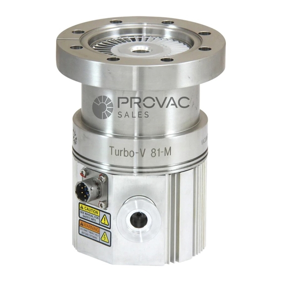
Turbo-V 81-M
Models:
87-900-983-01(D)
FEBRUARY 2008
969-8901
969-8902
969-8903
969-8904
(I)
MANUALE DI ISTRUZIONI
(D)
BEDIENUNGSHANDBUCH
(F)
NOTICE DE MODE D'EMPLOI
(E)
MANUAL DE INSTRUCCIONES
(P)
MANUAL DE INSTRUÇÕES
(NL) BEDRIJFSHANDLEIDING
(DK) INSTRUKSTIONSBOG
(S)
BRUKSANVISNING
(N)
INSTRUKSJON MANUAL
(FIN) OHJEKÄSIKIRJA
(GR)
ODHGIES CRHSEWS
(H)
FELHASZNÁLÓI KÉZIKÖNYV
(PL) PODRECZNIK INSTRUKCJI
(CZ) NÁVOD K POUŽITÍ
(SK) NÁVOD NA OBSLUHU
(SLO) PRIROČNIK ZA NAVODILA
(GB) INSTRUCTION MANUAL
Advertisement
Table of Contents

Related Manuals for Varian Turbo-V 81-M Series


Summary of Contents for Varian Turbo-V 81-M Series
- Page 1 MANUALE DI ISTRUZIONI BEDIENUNGSHANDBUCH NOTICE DE MODE D’EMPLOI MANUAL DE INSTRUCCIONES Turbo-V 81-M MANUAL DE INSTRUÇÕES (NL) BEDRIJFSHANDLEIDING (DK) INSTRUKSTIONSBOG Models: BRUKSANVISNING 969-8901 INSTRUKSJON MANUAL 969-8902 (FIN) OHJEKÄSIKIRJA 969-8903 (GR) ODHGIES CRHSEWS 969-8904 FELHASZNÁLÓI KÉZIKÖNYV (PL) PODRECZNIK INSTRUKCJI (CZ) NÁVOD K POUŽITÍ (SK) NÁVOD NA OBSLUHU (SLO) PRIROČNIK ZA NAVODILA (GB) INSTRUCTION MANUAL...
- Page 2 Turbo-V 81-M...
-
Page 5: Table Of Contents
ISTRUZIONI PER L’USO ...........................1 GEBRAUCHSANLEITUNG ..........................4 MODE D’EMPLOI ...............................7 INSTRUCCIONES DE USO ..........................10 INSTRUÇÕES PARA O USO...........................13 GEBRUIKSAANWIJZINGEN..........................16 BRUGSANVISNING ............................19 BRUKSANVISNING............................22 BRUKERVEILEDNING .............................25 KÄYTTÖOHJEET .............................28 PDHGIES CRHSEWS ............................31 HASZNÁLATI UTASÍTÁS ..........................34 INSTRUKCJA UZYTKOWANIA........................37 PŘÍRUČKA K POUŽITÍ.............................40 NÁVOD K POUŽITIU............................43 NAVODILA ZA UPORABO..........................46 INSTRUCTIONS FOR USE..........................49 TECHNICAL INFORMATION ...........................52 DESCRIPTION OF THE TURBO-V 81-M..................52... -
Page 6: Instructions For Use
INSTRUCTIONS FOR USE Safety Guideline Turbomolecular Pumps Turbomolecular pumps as described in the following operating manual contain a large amount of kinetic energy due to the high rotational speed in combination with the specific mass of their rotors. In case of a malfunction of the system for example rotor/stator contact or even a rotor crash the rotational energy may be released. -
Page 7: General Information
Varian before operating the equipment. to handle components which will be exposed to vacuum. Al- Varian will not be held responsible for any events occurring due ways use gloves or other appropriate protection. to non-compliance, even partial, with these instructions, im-... - Page 8 INSTRUCTIONS FOR USE The Turbo-V 81-M pumps must be used in conjunction with one of the suitable Varian controller and they must be connected to WARNING! a primary pump (see "Technical Information"). When employing the pump for pumping toxic, flammable, or...
-
Page 9: Technical Information
TECHNICAL INFORMATION Proceeding from the high vacuum to the forevac- DESCRIPTION OF THE TURBO-V 81-M uum region, the turbine stages sequence is: The Turbo-V 81-M pump is available in four ver- sions. The difference among the four versions lies • 1st stage with a blade angle of 40°, purely in the high vacuum connection. -
Page 10: Technical Specification
Forced air or water optional KF 40: 1.96 (4.32) CFF 4.5”: 2.96 (6.53) Recommended mechanical: Varian DS 42 – DS 102 CFF 2.75”: 2.77 (6.11) forepump dry pump: Varian SH 100 Operating position * (According to standard DIN 28 428, the base pressure is that Coolant water flow: 10 l/h (0.05 GPM) -
Page 11: Turbo-V 81-M Outline
TECHNICAL INFORMATION TURBO-V 81-M OUTLINE The following figure shows the Turbo-V 81-M outlines (dimensions are in inches [mm]). Turbo-V 81-M outline 54/63 87-900-983-01(D) - Page 12 TECHNICAL INFORMATION Graph of pumping speed vs inlet pressure with a 8 m /h mechanical pump Graph of compression ratio vs foreline pressure 55/63 87-900-983-01(D)
-
Page 13: Inlet Screen Installation
TECHNICAL INFORMATION The screen can be removed as shown in the fol- INLET SCREEN INSTALLATION lowing figure. The inlet screens mod. 969-9300 and 969-9309 prevent the blades of the pump from being dam- aged by debris greater than 0.7 mm diameter. The inlet screen, however, does reduce the pump- The following figure shows the overall flange di- ing speed by about 10%. -
Page 14: Heater Band Installation
TECHNICAL INFORMATION HEATER BAND INSTALLATION CAUTION If the chamber of the system is "baked" at a high temperature, a shield should be installed to pre- vent thermal radiation heating the high vacuum flange on the pump. The maximum temperature allowed for the inlet flange is 120° C. AIR COOLING KIT INSTALLATION An air cooling kit (mod. -
Page 15: Water Cooling Kit Installation
TECHNICAL INFORMATION WATER COOLING KIT INSTALLATION Two types of water cooling kits are available to be mounted when the pump is used under heavy load conditions or when air cooling is insufficient. The two model part numbers are: 969-9823 (me- tallic model), and 969-9824 (plastic model). -
Page 16: Vent Accessories
TECHNICAL INFORMATION 2. Assemble the metal or the plastic kit as shown. Cooling may be carried out either through an open circuit with eventual discharge of the water, or us- ing a closed circuit cooling system. The water temperature must be between +15 °C and +35 °C, with an inlet pressure between 2 and 4 bar. -
Page 17: Vibration Isolator Installation
TECHNICAL INFORMATION Then screw the vent valve into the pump and TYPICAL LAYOUT DIAGRAM tighten it using a 16 mm hexagonal spanner with a torque of 2.5 Nm. With Navigator Controller Turbo-V Navigator controller Vent valve Vacuum pump shut-off valve (optional) System vent valve (optional) Vacuum chamber CAUTION... -
Page 18: With Standard Rack Controller
Oil mist eliminator Fore-vacuum pump with internal one-way valve 10. Fore-vacuum pump control relay For ConFlat flange connections we recommend using Varian hardware. 11. Connection for water cooling 12. Roughing line with valve (optional) To facilitate assembly and dismantling, apply Fel- pro C-100 high temperature lubricant to the screw 13. -
Page 19: Connection Configurations
TECHNICAL INFORMATION Connection configurations Connection B - FORE-VACUUM PUMP Connection C - ELECTRICAL A flange KF 16 NW is available to connect the Turbo-V 81-M pump to the fore-vacuum pump. A hose or vacuum approved pipe can be used. If a rigid pipe is used, any vibration generated by the mechanical pump must be eliminated through the use of bellows. -
Page 20: Pump Used In Presence Of Magnetic Fields
Turbo-V 81-AG Navigator Controller 969-8996 100-240 Vac For a complete overview of Varian's extensive product lines, please refer to the Varian catalog. VENT VALVE MODEL SELECTION TABLE CONTROL UNIT MODEL VENT VALVE PART NUMBER Turbo-V 81-AG Navigator Controller N.O. - Page 21 NOTE: If a product is received at Varian which is contaminated with a toxic or hazardous material that was not disclosed, the customer will be held responsible for all costs incurred to ensure the safe handling of the product, and is liable for any harm or injury to Varian employees as well as to any third party occurring as a result of exposure to toxic or hazardous materials present in the product.
- Page 22 Request for Return FAILURE REPORT TURBO PUMPS and TURBOCONTROLLERS POSITION PARAMETERS Power: Rotational Speed: Does not start Noise Vertical Current: Inlet Pressure: Does not spin freely Vibrations Horizontal Temp 1: Foreline Pressure: Does not reach full speed Leak Upside-down Mechanical Contact Overtemperature Other: Temp 2:...
- Page 23 Toll Free # 1 (800) 882 7426 Tel: 00 800 234 234 00 vtt.technical.support@varianinc.com China Mexico Varian Technologies - Beijing Varian, S. de R.L. de C.V. Rm 1648 Central Tower South Wing Concepcion Beistegui No 109 China Beijing Junefield Plaza Col Del Valle No.
Need help?
Do you have a question about the Turbo-V 81-M Series and is the answer not in the manual?
Questions and answers