Table of Contents
Advertisement
Navigator
Pump models:
969-8918
969-8920
Kit models:
969-8824
969-8826
969-8828
969-8830
Controller model:
969-8972
87-900-946-01(B)
MARCH 2003
TV 301
969-8919
969-8921
969-8825
969-8827
969-8829
969-8831
969-8973
MANUALE DI ISTRUZIONI
BEDIENUNGSHANDBUCH
NOTICE DE MODE D'EMPLOI
MANUAL DE INSTRUCCIONES
MANUAL DE INSTRUÇÕES
BEDRIJFSHANDLEIDING
INSTRUKSTIONSBOG
BRUKSANVISNING
INSTRUKSJON MANUAL
OHJEKÄSIKIRJA
ODHGIES CRHSEWS
INSTRUCTION MANUAL
Advertisement
Table of Contents

Related Manuals for Varian TV 301 Navigator 969-8918


Summary of Contents for Varian TV 301 Navigator 969-8918
- Page 1 MANUALE DI ISTRUZIONI TV 301 BEDIENUNGSHANDBUCH Navigator NOTICE DE MODE D’EMPLOI MANUAL DE INSTRUCCIONES Pump models: MANUAL DE INSTRUÇÕES 969-8918 969-8919 BEDRIJFSHANDLEIDING 969-8920 969-8921 INSTRUKSTIONSBOG Kit models: 969-8824 969-8825 BRUKSANVISNING 969-8826 969-8827 INSTRUKSJON MANUAL 969-8828 969-8829 OHJEKÄSIKIRJA 969-8830 969-8831 ODHGIES CRHSEWS Controller model: INSTRUCTION MANUAL 969-8972...
- Page 2 TV 301 Navigator...
-
Page 5: Table Of Contents
ISTRUZIONI PER L’USO..........................1 GEBRAUCHSANLEITUNG...........................3 MODE D’EMPLOI ............................5 INSTRUCCIONES DE USO..........................7 INSTRUÇÕES PARA O USO ........................9 GEBRUIKSAANWIJZINGEN ........................11 BRUGSANVISNING ...........................13 BRUKSANVISNING............................15 BRUKERVEILEDNING ..........................17 KÄYTTÖOHJEET ............................19 PDHGIES CRHSEWS .............................21 INSTRUCTIONS FOR USE ........................23 TECHNICAL INFORMATION........................25 DESCRIPTION OF THE TV 301 NAVIGATOR ...............25 Pump Description......................25 Controller Description....................26 TECHNICAL SPECIFICATION....................26... -
Page 6: Istruzioni Per L'uso
Se, per qualsiasi ragione, il tempo di immagazzinamento è supe- riore, occorre reinviare la pompa in fabbrica. Per ogni informazio- ne, si prega di contattare il locale rappresentante della Varian. PREPARAZIONE PER L'INSTALLAZIONE Il TV 301 Navigator viene fornito in un imballo protettivo speciale;... - Page 7 In caso di guasto è possibile usufruire del servizio di riparazione superiore a 120 °C. Varian o del "Varian advanced exchange service", che permette di ottenere un sistema rigenerato in sostituzione di quello guasto. PERICOLO! NOTA Non far funzionare mai la pompa se la flangia di ingresso non è...
-
Page 8: Gebrauchsanleitung
Umgebungen installiert und/oder benutzt werden. LAGERUNG Beim Betrieb müssen folgende Umgebungsbedingungen eingehalten Um ein Höchstmaß an Effizienz und Zuverlässigkeit der Varian Tur- werden: bomolekularpumpen zu gewährleisten, sind die folgenden Anweisun- Maximaler Druck: 2 bar über dem atmosphärischen Druck gen zu beachten: Temperatur: von +5°C bis +35°C (siehe Diagramm im An-... - Page 9 120°C nicht überschreiten. pengehäuse unter 50°C abgesunken ist. GEFAHR! Bei Defekten kann der Varian Service oder der "Varian advanced exchange service" in Anspruch genommen werden, der ein gene- Die Pumpe darf nicht in Betrieb genommen werden, wenn der ralüberholtes System als Ersatz für das defekte System zur Ver- Eingangsflansch nicht an die Vakuumkammer angeschlossen fügung stellt.
-
Page 10: Mode D'emploi
Avant toute utilisation de l'appareil, il est conseillé à l'utilisa- teur de lire attentivement cette notice d'instructions ainsi que toute autre indication supplémentaire fournie par Varian qui décline par ATTENTION! conséquent toute responsabilité en cas de non respect total ou Afin d'éviter tout problème de dégazage, ne pas toucher, à... - Page 11 La turbopompe à bride d'entrée ConFlat doit être fixée à la cham- "RS232 COMMUNICATION DESCRIPTION" dans l'appendice bre à vide à l'aide des éléments mécaniques Varian prévus à cet "Technical Information"). effet. Pour tout autre détail, se reporter à l'appendice "Technical La LED verte LD1 placée sur le panneau de la base du TV 301...
-
Page 12: Instrucciones De Uso
CEE 85/399 para la Este equipo es para uso profesional. El usuario ha de leer atentamente preservación del medio ambiente. el presente manual de instrucciones y cualquier otra información suplementaria facilitada por Varian antes de usar el aparato. Varian se considera libre posibles... - Page 13 El LED verde LD1 situado en el panel de la base del TV 301 Varian. Para más detalles véase el anexo “Technical Information”. indica, con la frecuencia de su parpadeo, las condiciones...
-
Page 14: Instruções Para O Uso
Esta aparelhagem destina-se a uso profissional. O utilizador deve ler 85/399 para a protecção do meio ambiente. atentamente o presente manual de instruções e todas as informações adicionais fornecidas pela Varian antes de utilizar a aparelhagem. A Varian não se responsabiliza pela inobservância total ou parcial das ATENÇÃO! instruções, pelo uso indevido por parte de pessoas não treinadas, por... - Page 15 Em caso de defeito é possível usufruir do serviço de assistência superior a 120 ºC. Varian ou do "Varian advanced exchange service", que permite obter um sistema regenerado que substitua a bomba com defeito. PERIGO! NOTA Nunca activar a bomba se o flange de entrada não estiver ligado à...
-
Page 16: Gebruiksaanwijzingen
Varian verstrekte informatie door te lezen alvorens EEG milieurichtlijn 85/399. het apparaat in gebruik te nemen. Varian acht zich niet aansprakelijk voor de gevolgen van het niet of gedeeltelijk in acht nemen van de aanwijzingen, onoordeelkundig gebruik door niet... - Page 17 120° C bedragen. In geval van storing is het mogelijk om de reparatiedienst van Varian of de "Varian advanced exchange service" in te schakelen: zo krijgt men een ruilpomp ter vervanging van de defecte pomp. GEVAAR! Laat de pomp nooit draaien als de inlaatflens niet op de vacuümkamer...
-
Page 18: Brugsanvisning
Komponenter, der skal udsættes for vakuum, må ikke berøres Varian, før udstyret anvendes. Varian tager ikke ansvar for skader med bare hænder, idet der er risiko for afgasning. Anvend altid helt eller delvis som følge af tilsidesættelse af disse instruktioner, handsker eller anden lignende beskyttelse. - Page 19 Turbopumpen med ConFlat indløbsflange skal tilsluttes på “COMMUNICATION DESCRIPTION” bilaget “Teknisk vakuumkammeret ved hjælp af Varian monteringsudstyret. I Information”). bilaget “Teknisk Information” findes yderligere detaljer. Den grønne LED LD1, der er anbragt på panelet på TV 301’s fundament, angiver systemets funktion ved blink: BEMÆRK...
-
Page 20: Bruksanvisning
övrig dokumentation från Komponenter som skall utsättas för vakuum får inte hanteras med Varian före användning av utrustningen. Varian tar inget ansvar bara händer p g a kontamineringsrisken. Använd alltid handskar för skador helt eller delvis till följd av åsidosättande av eller liknande skydd. - Page 21 ConFlat fästas till frekvensen av dess blinkningar, hur systemet fungerar: vakuumkammaren med hjälp av Varian fästdelar. För detaljer • fast sken: pumpen roterar normalt; hänvisas till bilaga ”Technical Information” • långsamt blinkande (ungefär var 400 ms) : systemet är i lage för acceleration, bromsning, Stop eller "Waiting for interlock";...
-
Page 22: Brukerveiledning
Brukeren bør lese denne brukerveiledningen og all annen For å unngå avgassingsproblemer, må ingen del som skal informasjon fra Varian før utstyret tas i bruk. Varian kan ikke utsettes for vakuum håndteres med bare hendene. Bruk alltid holdes ansvarlig for hendelser som skjer på grunn av manglende hansker eller andre og passende verneutstyr. - Page 23 COMMUNICATION Turbopumpen med ConFlat inngangsflens skal festes til DESCRIPTION” i tillegget “Teknisk Informasjon”). vakuumkammeret ved hjelp av de spesielle låsedelene fra Varian. Den grønne lysdioden LD1 på TV 301 basepanel angir systemets For detaljer henvises det til “Teknisk informasjon”. funksjon ved hjelp av blink: den lyser fast: pumpen roterer normalt den blinker langsomt (ca.
-
Page 24: Käyttöohjeet
Jotta kaasun vuoto-ongelmilta vältyttäisiin, ei tyhjiölle altistuviin käyttöönottoa tulee käyttäjän lukea huolellisesti ohjekirja ja muut osiin tule koskea paljain käsin. Käyttäkää aina käsineitä tai muuta Varianin toimittamat lisätiedot. Varian ei ota vastuuta seurauksista, sopivaa suojausta. jotka johtuvat laitteen käyttöohjeiden täydellisestä tai osittaisesta laiminlyönnistä, ammattitaidottoman henkilön virheellisestä... - Page 25 50ºC:en. Älkää käyttäkö pumppua, ellei sisääntulolaippaa ole kytketty tyhjiökammioon tai pumppua suljettu sulkulaipalla. Laitteen vahingoittuessa mahdollista käyttää Varianin Älkää koskeko turbopumppuun tai sen lisäosiin lämmittämisen korjauspalvelua tai "Varian advanced exchange service" - aikana. Korkea lämpötila saattaa aiheuttaa henkilöiden vaihtopalvelua, jonka...
-
Page 26: Pdhgies Crhsews
PROSOCH egceir∂diou odhgièn kai opoiadÿpote £llh prÒsqeth plhrofor∂a pou d∂nei h Varian, prin apÒ th crhsimopo∂hsh thj suskeuÿj. H Gia na apofÚgete problÿmata apagwgÿj aer∂ou, mhn agg∂zete me Varian den f◊rei kamm∂a euqÚnh Òson afor£ thn olikÿ ÿ merikÿ... - Page 27 H uyhlÿ qermokras∂a mpore∂ na antl∂aj na e∂nai katèterh apÒ 50°C. prokal◊sei proswpik◊j bl£bej. Se per∂ptwsh bl£bhj mpore∂te na apeuqunqe∂te sto service thj Varian ÿ sto “Varian advanced exchange service”, pou saj d∂nei PROSOCH th dunatÒthta na antikatastÿsete thn calasm◊nh antl∂a me m∂a Apofuvgete sugkrouvseiÇ,...
-
Page 28: Instructions For Use
If for any reason the shelf life time is exceeded, the pump has to Do not remove the adhesive and protective cap before connect- be returned to the factory. Please contact the local Varian Vacuum ing the turbopump to the system. - Page 29 120 °C. ture of the pump falls below 50 °C. In the case of breakdown, contact your local Varian service center WARNING! who can supply a reconditioned system to replace that broken Never use the turbopump when the inlet flange is not connected to down.
-
Page 30: Technical Information
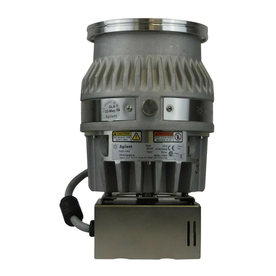
TECHNICAL INFORMATION DESCRIPTION OF THE TV 301 NAVIGATOR The TV 301 Navigator pumping system consists of a pump with a dedicated controller fixed to it. The system is available in various models that differ in the high vacuum flange and the controller. The TV 301 Navigator pump models are: −... -
Page 31: Controller Description
The pump can be water cooled or air cooled: in Start-up time < 3 minutes the first case the customer can use the dedicated Recommended mechanical: Varian SD 300 channels on the pump body, in the second case forepump diaphragm: Varian MD 60 an external optional fan is available. -
Page 32: Tv 301 Navigator Outline
TECHNICAL INFORMATION TV 301 NAVIGATOR OUTLINE NOTE The following figures show the TV 301 Navigator When the TV 301 Navigator has been stored at a outlines (dimensions are in inches [mm]). temperature less than 5°C, wait until the system has reached the above mentioned temperature. - Page 33 TECHNICAL INFORMATION Graph of nitrogen pumping speed vs inlet pressure Graph of compression ratio vs foreline pressure 87-900-946-01(B)
- Page 34 TECHNICAL INFORMATION Graph of nitrogen throughput vs inlet pressure using the recommended mechanical forevacuum pump Graph of nitrogen throughput test 87-900-946-01(B)
-
Page 35: Interconnections
TECHNICAL INFORMATION INTERCONNECTIONS J5 - IN-OUT The following figure shows the TV 301 intercon- nections. This connector carries all the input and output sig- nals to remote control the TV 301 Navigator. It is a 15-pins D type connector; the available sig- nals are detailed in the table, the following para- graphs describe the signal characteristics and use. - Page 36 TECHNICAL INFORMATION For example: SPEED SETTING: PWM input signal to set the - reference quantity: frequency pump speed. The PWM signal characteristics - threshold: 500 Hz must be the following: • - hysteresis: 1% frequency: 100 Hz +/-20% - activation type: "high level" •...
- Page 37 TECHNICAL INFORMATION How to connect the open collector input of the controller Here below there are the typical connections of the open collector input of TV301 Navigator to an external system. Two cases are considered: 1. the customer supplies the 24 Vdc 2.
-
Page 38: P2 - Serial
TECHNICAL INFORMATION How to connect the outputs of the controller INPUT POWER CONNECTION ON THE MODEL 969-8972 The following figure shows a typical logic output The following figure shows the input power con- connection (relay coil) but any other device may nection relevant to the model n. - Page 39 TECHNICAL INFORMATION − <STX> (Start of transmission) = 0x02 Source: Controller Destination: PC − <ADDR> (Unit address) = 0x80 (for RS 232) <ADDR> (Unit address) = 0x80 + device num- ber (0 to 31) (for RS 485) − <WIN> (Window) = a string of 3 numeric char- STX ADDR ACK ETX acter indicating the window number (from ‘000’...
-
Page 40: Window Meanings
(on = closed) (default) or Serial Serial = 0 (default = 1) configuration (default = 1) Reserved to Varian service Soft Start YES = 1 (write only in Stop NO = 0 Set the vent valve Automatic = 0 (see... -
Page 41: Inlet Screen Installation
CRC Param. (PA) PA8XXXX (where “XXXX” are variable) CRC Parameter "XXXX" structure Reserved to Varian service RS 485 address 0 to 31 (default = 0) Serial type select 0 = RS 232 1 = RS 485 (default = 0) NOTES 1. -
Page 42: Heater Band Installation
TECHNICAL INFORMATION The screen can be removed as shown in the fol- HEATER BAND INSTALLATION lowing figure. The heater band model 969-9804 and 969-9803 can be used to heat the pump casing when a bakeout is needed. The heater band is applied to the upper part of the pump casing, as shown in the figure, and heats it to a temperature of about 80°... -
Page 43: Air Cooling Kit Installation
TECHNICAL INFORMATION To fix the fan to the TV 301 case execute the fol- CAUTION lowing procedure (see the following figure): If the chamber of the system is "baked" at a high temperature, a shield should be installed to pre- 1. -
Page 44: Water Cooling Kit Installation
TECHNICAL INFORMATION The metallic model is assembled as shown in the WATER COOLING KIT INSTALLATION figure. Two types of water cooling kits are available to be mounted when the pump is used under heavy load conditions or when air cooling is insufficient. The two model part numbers are: 969-9337 (me- tallic model), and 969-9347 (plastic model). -
Page 45: Vent Accessories
TECHNICAL INFORMATION VENT ACCESSORIES The vent valve and vent device allow to avoid un- desired venting of the pump during temporary power failure and enables an automatic vent op- eration. TV 301 Navigator Controller Compatible Vent Valve mod. 969-9834 This vent valve waits before opening a minimum CAUTION time of about 5 sec. -
Page 46: Vibration Isolator Installation
TECHNICAL INFORMATION Vent Device mod. 969-9831 VIBRATION ISOLATOR INSTALLATION Four vibration isolators for ISO and CFF inlet flange version pumps are available as accesso- ries. The four model part numbers are the following: − model 969-9344 for ISO 100 flange; −... -
Page 47: Serial Cable Installation
TECHNICAL INFORMATION and then screw the gas purge valve (with a torque TV 301 CONTROLLER INSTALLATION of 2.5 Nm) as shown in the following figure. The controller can be mounted in two position: − bottom mounting (as per the complete system) −... -
Page 48: Typical Layout Diagram
TECHNICAL INFORMATION Side mounting TYPICAL LAYOUT DIAGRAM NOTE With Navigator Controller The L-shaped bracket (P/N 969-9349) is available as an option. See the following figure. 1. Screw the 4 fixing studs (provided with the ac- cessories bag) in the holes on the L-shaped bracket;... -
Page 49: With Standard Rack Controller
10. Fore-vacuum pump control relay For ConFlat flange connections we recommend 11. Connection for water cooling using Varian hardware. 12. Roughing line with valve (optional) To facilitate assembly and dismantling, apply Fel- 13. Turbopump pro C-100 high temperature lubricant to the screw threads protruding from the flange and between 14. -
Page 50: Connection Configurations
TECHNICAL INFORMATION Connection configurations Connection B - FORE-VACUUM PUMP Connection C - ELECTRICAL A flange KF 16 NW is available to connect the Turbo-V301 pump to the fore-vacuum pump. A hose or vacuum approved pipe can be used. If a rigid pipe is used, any vibration generated by the mechanical pump must be eliminated through the use of bellows. -
Page 51: Pump Used With Corrosive Gases
3. Gas purge valve CAUTION 4. Gas purge port 5. Forevacuum pump To prevent bearing damage, Varian suggests a 6. Turbopump minimum purge gas flow rate of 10 sccm (0.17 7. Vent valve mbar l/s). This value can be exceeded, according to the process requirements. -
Page 52: Pump Used In Presence Of Magnetic Fields
969-9334 Vibration isolator, ISO 160 969-9345 However if the effect is grater, than the case should be carefully reviewed by Varian's special- Vibration isolator, CF 8" 969-9335 ist. As a matter of fact, in case of high magnetic Vent flange, NW 10 KF / M8... - Page 53 NOTE: If a product is received at Varian which is contaminated with a toxic or hazardous material that was not disclosed, the customer will be held responsible for all costs incurred to ensure the safe handling of the product, and is liable for any harm or injury to Varian employees as well as to any third party occurring as a result of exposure to toxic or hazardous materials present in the product.
- Page 54 Request for Return FAILURE REPORT TURBO PUMPS and TURBOCONTROLLERS POSITION PARAMETERS Power: Rotational Speed: Does not start Noise Vertical Current: Inlet Pressure: Does not spin freely Vibrations Horizontal Temp 1: Foreline Pressure: Does not reach full speed Leak Upside-down Mechanical Contact Overtemperature Other: Temp 2:...
- Page 55 Tel: (39) 011 997 9111 Tel: (39) 011 997 9111 Fax: (39) 011 997 9350 Brazil Fax: (39) 011 997 9350 Varian Industria e Comercio Ltda. Japan Avenida Dr. Cardoso de Mello 1644 Internet Users: Varian Vacuum Technologies Vila Olimpia Customer Service &...
Need help?
Do you have a question about the TV 301 Navigator 969-8918 and is the answer not in the manual?
Questions and answers