Table of Contents
Advertisement
Quick Links
Introduction
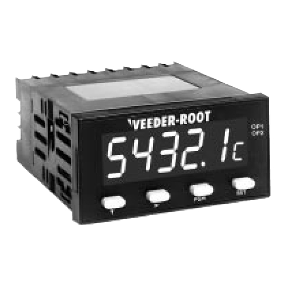
Your Veeder-Root brand C628 Batch Counter is one model in a family of 1/8 DIN units
which offers breakthrough display technology as well as easy-to-program single-line
parameters. Designed to provide instant visual feedback regarding an application's key
input value, the C628 not only has a 0.71" high LED display (27% larger than other 1/8
DIN units), but also the ability to change display color based on process status
(programmable parameter in Operation Mode). Easy programming is made possible via a
help function and a secondary legend display.
This manual will guide you through the installation and wiring of your C628 unit with
information on proper panel mounting and rear terminal layout and wiring instructions.
In addition, the instrument's operation and programming modes are thoroughly
explained. The Operation Mode provides day to day operation and allows editing of
preset values. The Program Mode enables the configuration of various parameters prior
to initial operation. These parameters include those for basic configuration as well as
other settable features which will enhance the functionality and usability of the device.
This manual also provides
information on the C628
Batch Counter's presets,
transistor and relay outputs,
product specifications, and
ordering and warranty
procedures.
Features
• AWESOME 0.71" high digit LED display
• Programmable color change display based on
an event
• Independent display of background total
• Programmable help function and secondary
legend display
• Choice of NPN or PNP primary input
• Filter speed settable for 20, 200, or 10,000 Hz
• Standard outputs: two NPN transistors & one
relay (optional 2nd relay)
• Front panel reset enable and preset lockout
• Optional RS-485 plug in card
• CE approved
Index
page 2
page 3
page 4
page 5
page 6-10
page 11
page 12
page 12
Technical Manual
702138-0008
Veeder-Root
brand
Series C628
Batch Counter
(C628-9XXX)
Advertisement
Table of Contents

Related Manuals for Veeder-Root C628 Series


Summary of Contents for Veeder-Root C628 Series
-
Page 1: Table Of Contents
Introduction Your Veeder-Root brand C628 Batch Counter is one model in a family of 1/8 DIN units which offers breakthrough display technology as well as easy-to-program single-line parameters. Designed to provide instant visual feedback regarding an application’s key input value, the C628 not only has a 0.71” high LED display (27% larger than other 1/8 DIN units), but also the ability to change display color based on process status (programmable parameter in Operation Mode). -
Page 2: Installation
I N S T A L L A T I O N PANEL MOUNTING 100mm VEEDER-ROOT 82344 48mm 96mm 10mm 92mm +0.5 -0.0 PANEL 45mm CUTOUT +0.5 -0.0 SIZE The instrument can be mounted in a panel with a thickness of up to 6mm. The... -
Page 3: Wiring
I N S T A L L A T I O N WIRING REAR TERMINAL CONNECTIONS Power Supply RS-485 Comm. Relay 1 + VDC - (opt.) 14 15 Relay 2 (opt.) Count Inputs units. The neutral side for AC powered units and the negative side for DC powered units are connected to Terminal #14. -
Page 4: Operation
O P E R A T I O N FRONT PANEL Primary Display VEEDER-ROOT Output Indicators 82345 Secondary Display Down Key Scroll Key Program Key Reset Key Key Functions Display Functions Function Function Display Down In Operation Mode: Used in edit operation to decrement Primary In Operation Mode: Default display is the count value. -
Page 5: Operation Mode
O P E R A T I O N OPERATION MODE CHANGING A PRESET VALUE Default display is the present count Use the Scroll Key to move from left to VEEDER-ROOT VEEDER-ROOT 34567 23456 value. right and highlight the digit that needs to be changed. -
Page 6: Programming
P R O G R A M M I N G PROGRAM MODE ENTERING PROGRAM MODE AND BASIC OPERATION The Program Mode can be accessed from the VEEDER-ROOT 23456 Operation Mode by holding the Program Key for 3 seconds. for 3 seconds... - Page 7 P R O G R A M M I N G PROGRAM MODE Continued Count Mode c o u n t Function: Defines how the input pulses will be applied to the count value Adjustment Range: d i r Q u A d A+B: Inputs on both the A-B: Inputs on the A Directional: When input...
- Page 8 P R O G R A M M I N G PROGRAM MODE Continued Filter Speed S P E E d Function: Enables the debounce filter of the counter to properly match the application Adjustment Range: 2 0 0 1 0 0 0 0 20: The unit will accept 200: The unit will accept 10,000: The unit will...
- Page 9 P R O G R A M M I N G PROGRAM MODE Continued Serial Communication Enabled C o < > S Function: Activates the RS-485 communication option board Adjustment Range: n o n E F i t None: No communication Fitted: A communication board installed board is installed in the...
- Page 10 P R O G R A M M I N G PROGRAM MODE Continued Preset Lock L o c / Function: Determines whether the Preset Values can be changed via the front panel Adjustment Range: d i S Enable: Preset values Disabled: Preset values are read only can be viewed and...
-
Page 11: Appendix A Specifications
A P P E N D I X SPECIFICATIONS Count Inputs Electrical Type: Sinking/Sourcing or Contact Closure Supply Voltage: 90-264 VAC, 50/60 Hz, or 20-50 VAC/VDC Frequency: 10 kHz max. Power Consumption: 4 Watts Logic: Low < 2.0 VDC, High > 3.0, 30V max. Access. -
Page 12: General
G E N E R A L ORDERING INFORMATION C628 - 9 Power Supply 2nd Relay Option 0 90-264 VAC 0 None 2 20-50 VAC/VDC 1 2nd Relay Serial Communication Option 0 None 5 RS-485 Additional outputs and options can be field installed through plug-in boards which can be ordered separately.
Need help?
Do you have a question about the C628 Series and is the answer not in the manual?
Questions and answers