Table of Contents
Advertisement
Quick Links
Advertisement
Table of Contents

Related Manuals for Veeder-Root DIS-51


Summary of Contents for Veeder-Root DIS-51
- Page 1 • Manual No: 577014-445 Revision: C DIS-51 Installation, Setup & Operation Guide...
- Page 2 Notice Veeder-Root makes no warranty of any kind with regard to this publication, including, but not limited to, the implied warranties of merchantability and fitness for a particular purpose. Veeder-Root shall not be liable for errors contained herein or for incidental or consequential damages in connection with the furnishing, performance, or use of this publication.
-
Page 3: Table Of Contents
Wiring Diagram For Option 2 ..................10 Software Setup For Serial Port RS-232 On TLS-350R - Option 2 ..... 10 Connection Instructions - DIS-51 to TLS4 ..............11 RS-485 Serial Port Configuration On TLS4 .............. 11 Wiring Diagram ......................... 11 Software Setup For TLS4 Serial 2 Port .............. - Page 4 Table of Contents Sub-Menu Display Backlight ..................... 20 Sub-Menu Information ......................21 Entering and Changing the Security Code in DIS-51 ..........21 Operating Instructions Display Icons ......................... 24 Error screens ......................... 25 Alarm screens ........................25 Figures Figure 1. System Block Diagram ..................4...
-
Page 5: Overview
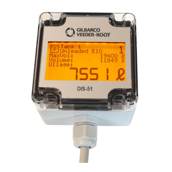
This manual describes the installation, setup, and operations for the DIS-51 unit sold by Gilbarco Veeder-Root. The DIS-51 displays ullage as determined by the TLS console up to the tank capacity. Use the display for this purpose only. Safety Precautions The following safety symbols are used throughout this manual to alert you to important safety hazards and precautions. -
Page 6: General
Keep out of reach of children! General The DIS-51 unit allows a tanker driver to connect with the station’s ATG to view continuous level measurements for up to 32 tanks, ullage for the tanks, as well as any alarms and warnings. -
Page 7: Product Components
• 2 Terminals (connector end stop for multiple series) • 1 DIN bar This kit includes the items you may need to connect the DIS-51 and push-button switch to the junction box. The kit does not include the wire/cable that goes from the console to the junction box. -
Page 8: Gauge Requirements
Figure 1. System Block Diagram Location The DIS-51 display is designed to be mounted against the inside window of the kiosk and visible to the tanker driver outside the window. After determining the ideal location for mounding the display, ensure the window is clean and dry. -
Page 9: Connections
Once installed avoid getting window cleaning agents, water, etc. onto the DIS-51 display. Connections The cable that comes with the DIS-51 is two meters long with 7 pole connections. The signals on this wire are shown in the Table 1 below. Table 1. DIS-51 Cable Signals... -
Page 10: Figure 2. Dis-51 Junction Box Wiring Diagram
Introduction Wiring Connections Figure 2. DIS-51 Junction Box Wiring Diagram... -
Page 11: Figure 3. Serial Comm Wiring Input Options
Introduction Wiring Connections Figure 3. Serial Comm Wiring Input Options... -
Page 12: Dis-51 To Tls Console Wiring Connections
Set jumper J3 onto pins 1 and 2 for 2-wire configuration (see Figure 4). Figure 4. Serial Port Configuration For TLS2P 1. Attach the RS-485 cable from the DIS-51 to TLS2P Serial Port 2 connector (J8) as shown in Figure 3. -
Page 13: Tls2P Software Setup For Dis-51
This is the preferred option and requires a Single Port Kit P/N 461-100-4102 which includes: • DIS-51 Interface Module for TLS-350R, provides single RS-485 Port, P/N 330799-001 (see Figure 5). Figure 5. Single Port RS-485 Module For TLS-350R - DCD Configuration... -
Page 14: Wiring Diagram For Option 1
Connection Instructions - DIS-51 To TLS-350R Wiring Diagram For Option 1 Figure 3 shows the wiring connection between the DIS-51 junction box and a TLS- 350R RS-485 Interface Module. Software Setup For Serial Port RS-485 On TLS-350R - Option 1 •... -
Page 15: Connection Instructions - Dis-51 To Tls4
When the communication between the DIS-51 Display and the TLS-4 is established, both LEDs should light up periodically. Wiring Diagram Figure 3 shows the wiring connections between the DIS-51 junction box and the TLS4 Serial 2 Port. Software Setup For TLS4 Serial 2 Port Go to Menu>Setup >... - Page 16 • Use Handshaking - No Handshaking • Security Code - Serial Command Security can be used but this requires that this feature is also enabled in the DIS-51 Display and that the Security Code is set to the same characters in both devices.
-
Page 17: Connection Instructions - Dis-51 To Tls-450 Series
DIS-51 To TLS Console Wiring Connections Connection Instructions - DIS-51 to TLS-450 Series Connection Instructions - DIS-51 to TLS-450 Series The RS-232/RS-485 Comm module (P/N 330020-618 for DIS-51 communication is shown in Figure 7. Figure 7. RS-232/RS-485 Comm Module For TLS-450/TLS-450PLUS RS-485 Serial Port Configuration On TLS-450/TLS-450PLUS 1. -
Page 18: Software Setup For Tls-450/Tls-450 Plus Serial 2 Port
DIS-51 To TLS Console Wiring Connections Connection Instructions - DIS-51 to TLS-450 Series Software Setup For TLS-450/TLS-450 PLUS Serial 2 Port Go to Menu>Setup > Communication > Serial Port and select Serial Port 2. Enter the following parameters: • Label - e.g. DIS-51 Display •... -
Page 19: Dis-51 Configuration Screens
DIS-51 Configuration Screens The user enters the Configuration Main Menu after pressing on the push-button switch for more than10 seconds. Once in the Configuration Main Menu, the following actions can be triggered by pressing the push-button switch as discussed below: Pressing the push-button switch for less than 2 seconds (short press): •... -
Page 20: Sub-Menu Language Selection
DIS-51 Configuration Screens Sub-Menu Language Selection Configuration Main Menu (scrolled down two lines): Configuration Main Menu (scrolled down three lines): Configuration Main Menu (scrolled down four lines): Sub-Menu Language Selection Available languages: via console ,English, Deutsch, Français, Español, Português, Italiano and русский. -
Page 21: Sub-Menu Tank Selection
DIS-51 Configuration Screens Sub-Menu Tank Selection Configuration, sub-menu Language, English selected: Configuration, sub-menu Language, Deutsch selected: Sub-Menu Tank Selection Configuration, sub-menu Tank selection, all tanks selected: Configuration, sub-menu Tank selection, multiple tanks selected: Configuration, sub-menu Tank selection, single tank selected:... -
Page 22: Sub-Menu Operating Mode
DIS-51 Configuration Screens Sub-Menu Operating Mode Sub-Menu Operating Mode Configuration, sub-menu operating mode, automatic mode selected: Configuration, sub-menu operating mode, manual mode selected: Sub-Menu Display Duration The contents of the sub-menu display duration depend on the selected operating mode. In operating mode automatic, a display duration of 3, 6 or 9 seconds can be selected (this is the time that the display stays on one tank before automatically switching over to the next tank). - Page 23 DIS-51 Configuration Screens Sub-Menu Display Duration Configuration, sub-menu display duration, 6 seconds selected: Configuration, sub-menu display duration, 9 seconds selected: When Manual mode is selected: Configuration, sub-menu display duration, 1 minute selected: Configuration, sub-menu display duration, 2 minutes selected:...
-
Page 24: Sub-Menu Display Backlight
DIS-51 Configuration Screens Sub-Menu Display Backlight Configuration, sub-menu display duration, 5 minutes selected: Configuration, sub-menu display duration, 10 minutes selected: Sub-Menu Display Backlight Configuration, sub-menu display backlight, no selected: Configuration, sub-menu display backlight, yes selected:... -
Page 25: Sub-Menu Information
Entering and Changing the Security Code in DIS-51 If you enable Serial Command Security in the console you must also enable it in the DIS-51, and the security code must be set to the same code in both the console and the DIS-51. - Page 26 DIS-51 Configuration Screens Entering and Changing the Security Code in DIS-51 2. Short press the push-button switch until you are at “enable code,” then long press to select it. 3. Short press the push-button switch until you are at “change code,” then long press to select it.
-
Page 27: Operating Instructions
The truck driver pushes the push button/switch to activate the display. The Site screen displays. It shows where the DIS-51 display is located. The site screen displays after start-up and each time that the display is activated by the external switch. -
Page 28: Display Icons
The level (volume) decreases. A delivery into the displayed tank is currently taking Delivery place. The level (volume) increases. The DIS-51 display is showing information data (e.g. site Information information). There is an error preventing the normal display of data Alarm and Error for a single tank or for all tanks. -
Page 29: Error Screens
Operating Instructions Error screens Error screens The error screens are not tank specific and are shown if there is a general problem. No communication with the console: No tanks configured (not a tank at all): Alarm screens The alarm screens are tank specific and are shown alternating with the tank data of the selected tank. - Page 30 Operating Instructions Alarm screens Overfill alarm (code 04), or maximum product alarm (code 12): Probe out alarm (code 09): Setup warning (code 01):...
- Page 31 Operating Instructions Alarm screens This page intentionally left blank.
Need help?
Do you have a question about the DIS-51 and is the answer not in the manual?
Questions and answers