Table of Contents
Advertisement
Quick Links
Advertisement
Table of Contents

Related Manuals for Veeder-Root Mag-FLEX


Summary of Contents for Veeder-Root Mag-FLEX
- Page 1 Manual No: 577014-042 ● Revision: E Mag-FLEX Probe Installation Manual...
- Page 2 Customer Service will work with production facility to have the replacement product shipped as soon as possible. If “lost” equipment is delivered at a later date and is not needed, Veeder-Root will allow a Return to Stock without a restocking fee.
- Page 3 Veeder-Root specifications, modified or repaired by unauthorized persons, or damage related to acts of God. If “Warranty” is purchased as part of the Fuel Management Service, Veeder-Root will maintain the equipment for the life of the contract in accordance with the written warranty provided with the equipment. A Veeder-Root Fuel Management Services Contractor shall have free site access during Customer’s regular working hours to work on the equipment.
-
Page 4: Table Of Contents
National Electrical Code Compliance ................9 Mag-FLEX Probe Wire Length .................9 Veeder-Root Parts ......................9 Example Drawings Example Mag-FLEX Probe Site Layout Drawing - Wireless Installation ......10 Example Mag-FLEX Probe Site Layout Drawing - Hard-Wired Installation ....11 Mag-FLEX Probe Length Calculation ................12 Probe Handling .......................13 System Safety Layout Field Cable Ducting / Cable Trays ..................14... - Page 5 Splice Length Dimensions ..............22 Figure 7. Splice Connections ................23 Figure 8. Removing Sealing Compound Clip ............24 Figure 9. Pouring Sealing Compound Into Sleeve ..........24 Tables Table 1. Dimensions For Mag-FLEX Probe Tank Opening ........7 Table 2. Part Number Nomenclature ...............9...
-
Page 6: Tank Gauge Requirements
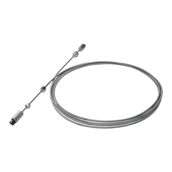
Tank Gauge Requirements The Mag-FLEX is a digital flexible probe able to read temperature, product level and water level in tanks up to 15.0 meters. The Mag-FLEX enables liquid height, water height and temperature to be measured within fuel storage vessels with maximum liquid levels up to 9.9 metres with TLS2 and 15.0 metres with TLS-3XX and TLS-450. -
Page 7: Related Documents
RELATED DOCUMENTS Documents Required to Install Equipment This intrinsically safe apparatus is only for use as part of a Veeder-Root Automatic Tank Gauging System (ATG Console with probes and sensors). To install intrinsically safe apparatus, use the specific control drawing that appears on the nameplate of the applicable associated apparatus (ATG Console): UL/cUL Control Drawing Document No. -
Page 8: Safety Symbols
Introduction Safety Symbols accompanying Compact Disk (TECH DOCS CD) or on the internet at veeder.com under SUPPORT; VR TECHNICAL DOCUMENTS; DRAWINGS. Product Label Contents I.S. CIRCUIT FOR HAZLOC DEVICE F/N 889590-XXX CL I, DIV. 1, GP.D S/N XXXXXX CL I, ZONE 0 -40°C <... -
Page 9: Safety Warnings
If you are not sure of the type of power source required, consult your Veeder-Root authorized service contractor. Mag-FLEX Probe cable length: The length of the cable from its exit point in the tank riser or tank fitting to the transmitter cannot exceed 10 feet. -
Page 10: Special Tools Required For Transmitter Installation
General AST Guidelines The Mag-FLEX Probe insertion length is critical to ordering and installing the correct probe into the correct tank. An improper probe length could result in the probe weight coming in contact with the tank bottom resulting in inaccurate fuel height measurement and possible probe damage. -
Page 11: Personal Protective Equipment
• The TLS RF console and receiver are installed. • The TLS console is installed. Note: the Mag-FLEX Probe is only compatible with TLS Consoles installed with Wireless 2 (2-Way) components supplied by V-R. The Mag-FLEX Probe is for inventory only applications. Leak detection is not available. -
Page 12: Mag-Flex Probe Overview
The Mag-FLEX Probe has a weight and magnet at the base of the probe to give stability, suitable for use in a wide range of products and available with or without water detection. The Mag-FLEX Probe with standard water float uses a process connection requiring a 1-½”... -
Page 13: Mag-Flex Technical Data
Part of Low Level Water Float Kit. Mag-FLEX Probes Part Number Specification Important: the instructions below are intended as reference material only, the Gilbarco Veeder-Root training modules contain comprehensive information and must be completed before any installation work is attempted -... -
Page 14: Mag-Flex Spare Parts And Accessories
AST tanks must be properly grounded according to NFPA 70 and applicable local codes and regulations. MAG-FLEX PROBE WIRE LENGTH Improper system operation could result in undetected potential environmental and health hazards if the Mag-FLEX Probe to TLS RF Transmitter wire runs exceed 10 feet. -
Page 15: Example Drawings
POWER I.S. 042-5 Figure 1. Site Drawing - Example TLS RF Wireless 2 System Site Layout – Two Mag-FLEX Probes LEGEND FOR NUMBERED BOXES IN Figure 1 8. Receiver To be installed in accordance with the National Electrical Code, NFPA 70 and the Code for Motor Fuel Dispensing Facilities and Repair Ga- 9. -
Page 16: Example Mag-Flex Probe Site Layout Drawing - Hard-Wired Installation
I.S. I.S. 042-4 Figure 2. Site Drawing - Example Hardwired System Site Layout – Two Mag-FLEX Probes LEGEND FOR NUMBERED BOXES IN Figure 2 10. 120 or 230 Vac from power panel - separate branch circuits are To be installed in accordance with the National Electrical Code, NFPA required for the TLS RF and TLS console. -
Page 17: Mag-Flex Probe Length Calculation
Mag-FLEX Probe Length Calculation Before ordering the Mag-FLEX Probe, an accurate dimension for “1” must be obtained. Measure internally the Insertion Length of ‘1’ from the 1½” entry point to the bottom of the tank (see Figure 3). Probe length for ordering purposes = Length of ‘1’... -
Page 18: Probe Handling
Probe Handling It is important to handle the Mag-FLEX probe with care at all times during the installation. Avoid excessive bending of the probe especially at the points the ridged sections meet with the flexible shaft. Below you can see examples of mishandling that would cause irreversible damage to the probe and invalidate the terms of warranty. -
Page 19: System Safety Layout
Installer’s responsibility to ensure that the installation complies with all relevant local and national legislation and codes of practice. Do not run the Mag-FLEX probe cable from the tank to the TLS Console in the same cable duct as non-intrinsically safe wiring. -
Page 20: Mag-Flex Installation & Handling Procedures
Installation requires a minimum of two people to allow correct handling of the probe. Please note that the flexible and therefore fragile nature of the Mag-FLEX probe makes it more prone to mechanical shock. The probe must not be unpacked until it has been brought to its place of installation and where possible unpacked at the Tank top. The probe corrugated shaft is supplied in a 1 meter diameter coil this coil MUST not be reduced in size. -
Page 21: Mag-Flex Probe Installation
Mag-FLEX Installation & Handling Procedures Mag-FLEX Probe Installation Mag-FLEX Probe Installation 1. Unpacking the Probe The probe shipping box is 1.1m square and12cm deep. The probe is coiled to a diameter of approximately 1m. The probe should not be unpacked until the tank is ready to accept it. - Page 22 Mag-FLEX Installation & Handling Procedures Mag-FLEX Probe Installation 3. Probe held ready for installation The coil should be held as shown maintain- ing the coiled shape to prevent kinking. 4. Process Connection With the 5mm hex key, loosen the socket cap screw and gland.
- Page 23 Mag-FLEX Installation & Handling Procedures Mag-FLEX Probe Installation 6. Feeding the probe into the tank Unroll the corrugated shaft as the probe is lowered into the tank taking care to avoid chafing on the tank entry. 7. Corrugated shaft lowered into tank...
- Page 24 Mag-FLEX Installation & Handling Procedures Mag-FLEX Probe Installation 9. Fitting the process connection Apply sealant to the thread of the process connection. Carefully lower the process connection into the tank entry fitting. Screw in and tighten using a 55mm WAF spanner.
-
Page 25: Figure 4. Junction Box Installation Examples
Surge Encapsulation Kit (P/N 848100-001) Protecter to tank (P/N 848100-002) Riser pipe ground Seal off Conduit with Probe field wiring to ATG Example Wireless Installation Example Hardwired Installation Figure 5. Veeder-Root Single- And Dual-Channel Encapsulation Kit Installation Examples... -
Page 26: Mag-Flex Probe Field Wiring Connections
Mag-FLEX Installation & Handling Procedures Mag-FLEX Probe Field Wiring Connections Mag-FLEX Probe Field Wiring Connections OPTIONAL JUNCTION BOX - WIRED INSTALLATIONS ONLY 12. Connecting the probe leader cable - Connect the leader cable supplied with the probe to the M12 con- nector located on the top of the probe canister. -
Page 27: Veeder-Root Encapsulation Kits
Mag-FLEX Installation & Handling Procedures Mag-FLEX Probe Field Wiring Connections 15. Grounding the optional junction box to the tank A 10 gauge (4mm²) earth cable must NOTICE be connected between the junction box and tank ground connection. The earth cable should be connected to the external saddle clamp of the junction box. -
Page 28: Figure 7. Splice Connections
Mag-FLEX Installation & Handling Procedures Mag-FLEX Probe Field Wiring Connections 2. Make the connections to the four black and white wires in the Encapsulation Kit using wire nuts as shown in Figure 7. Depending on the installation, cut off the TLS console or Transmitter cable’s bare shield wire at the cable jacket. -
Page 29: Figure 8. Removing Sealing Compound Clip
Mag-FLEX Installation & Handling Procedures Mag-FLEX Probe Field Wiring Connections Chemically resistant gloves Figure 8. Removing Sealing Compound Clip 5. Thoroughly mix compound together. Invert bag several times while squeezing compound from one end to the other for a minimum of one minute. -
Page 30: Tls Setup
Mag-FLEX Installation & Handling Procedures TLS setup TLS setup The TLS console Mag-FLEX setup is similar to that for a standard Mag Plus Probe setup. Listed below are the setup exceptions. FLOAT TYPE For TLS2, TLS-3XX or TLS-450 consoles, the float type must be set to 3” FLOAT (76.2 mm). - Page 31 For technical support, sales or other assistance, please visit: www.veeder.com...
Need help?
Do you have a question about the Mag-FLEX and is the answer not in the manual?
Questions and answers