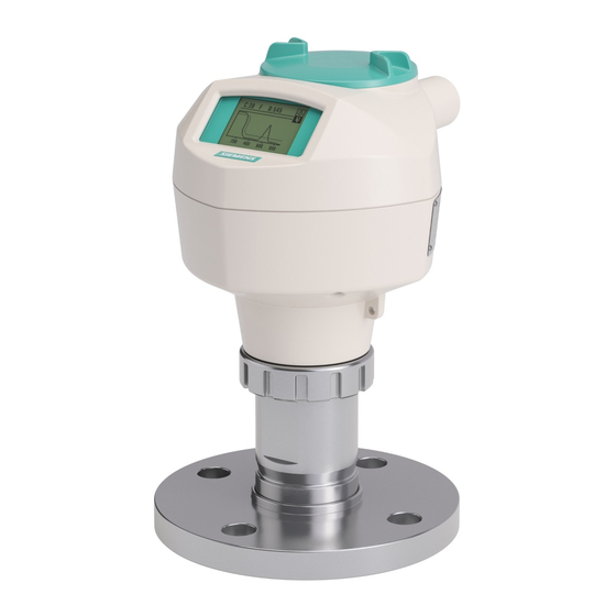
Siemens Sitrans LR250 Instruction Manual
Hide thumbs
Also See for Sitrans LR250:
- Operating instructions manual (306 pages) ,
- Quick start manual (272 pages) ,
- Instruction manual (175 pages)
Table of Contents
Advertisement
Quick Links
Download this manual
See also:
Instruction Manual
Advertisement
Table of Contents
Troubleshooting

Related Manuals for Siemens Sitrans LR250


Summary of Contents for Siemens Sitrans LR250
- Page 1 Instruction Manual June 2008 sitrans LR250 (PROFIBUS PA)
- Page 2 The user is responsible for all changes and repairs made to the device by the user or the user’s agent. • All new components are to be provided by Siemens Milltronics Process Instruments Inc. • Restrict repair to faulty components only.
-
Page 3: Table Of Contents
Safety marking symbols ......................1 FCC Conformity ............................1 The Manual ...............................2 Application Examples ........................2 Technical Support ............................2 Abbreviations and Identifications .......................3 SITRANS LR250 Overview ....................4 Specifications ........................5 Power............................. 5 Performance..........................5 Interface ............................6 Mechanical........................... 6 Environmental ..........................7 Process............................ - Page 4 Requesting an Echo Profile ........................32 Device Address ............................32 Level application example ........................33 Operating via SIMATIC PDM ..................34 Functions in SIMATIC PDM ........................34 Features of SIMATIC PDM Rev. 6.0, SP3 ................34 Features of SIMATIC PDM Rev. 5.2, SP1 ................35 Electronic Device Description (EDD) ..................35 Configuring a new device ......................35 Set Address ........................
- Page 5 PROFIBUS Ident Number ....................90 Powered Hours........................ 90 Power-on Resets......................90 Calibration Interval......................94 Communication.......................... 97 Device Address ....................... 97 Remote Lockout ......................97 Security............................98 Write Locking ........................98 Language............................. 98 Appendix A: Alphabetical Parameter List ..............99 Appendix B: Troubleshooting ..................101 Communication Troubleshooting ....................101 Device Status Icons ...........................
- Page 6 Appendix F: PROFIBUS PA Profile Structure ............. 128 PROFIBUS Level Device Design ......................128 Block Model ............................128 Description of the blocks ......................129 Appendix G: Communications via PROFIBUS PA ............. 133 Device Configuration tool ........................133 SIMATIC PDM ..........................133 Network Configuration ........................133 The GSD file ..........................133 Bus Termination ...........................134 Power Demands ..........................134 PROFIBUS address ..........................134...
-
Page 7: Safety Notes
FCC Conformity US Installations only: Federal Communications Commission (FCC) rules WARNING: Changes or modifications not expressly approved by Siemens Milltronics could void the user’s authority to operate the equipment. Notes: • This equipment has been tested and found to comply with the limits for a Class A digital device, pursuant to Part 15 of the FCC Rules. -
Page 8: The Manual
SITRANS LR250. • This manual applies to the SITRANS LR250 (PROFIBUS PA) only. This manual will help you set up your SITRANS LR250 for optimum performance. We always welcome suggestions and comments about manual content, design, and accessibility. -
Page 9: Abbreviations And Identifications
The output from the Level Transducer Block can be called the Primary Value (or Secondary Value). When it becomes the input to the AIFB, it is called the Process Variable. 7ML19985JF02 SITRANS LR250 (PROFIBUS PA) – INSTRUCTION MANUAL Page 3... -
Page 10: Sitrans Lr250 Overview
PROFIBUS Class I and Class II master. Programming SITRANS LR250 is very easy to install and configure via a graphical local user interface (LUI). You can modify the built in parameters either locally via the Siemens infrared hand- held programmer, or from a remote location via SIMATIC PDM. -
Page 11: Specifications
Specifications Notes: • Siemens Milltronics makes every attempt to ensure the accuracy of these specifications but reserves the right to change them at any time. Power Bus powered Per IEC 61158-2 (PROFIBUS PA) Current consumed 15.0 mA (General Purpose or Intrinsically Safe version) -
Page 12: Interface
Display quality will be degraded in temperatures below –25 °C (–13 °F) and above +65°C (+149 °F). For use with 1.5" (40 mm) horn antennas only. Hastelloy & C-22 are registered trademarks of Haynes International Inc. Page 6 SITRANS LR250 (PROFIBUS PA) – INSTRUCTION MANUAL 7ML19985JF02... -
Page 13: Environmental
O-ring materials, and vessel pressure. For more detail, or for Maximum Process Temperature Chart other configurations, see on page 119, Process Pressure/Temperature derating curves on page 120. Intrinsically Safe wiring on page 20 7ML19985JF02 SITRANS LR250 (PROFIBUS PA) – INSTRUCTION MANUAL Page 7... -
Page 14: Programmer (Infrared Keypad)
• To estimate the lifetime expectancy, check the nameplate on the back for the serial number. The first six numbers show the production date (mmddyy), for example, serial number 032608101V. Siemens Milltronics Infrared IS (Intrinsically Safe) Hand Programmer for hazardous and all other locations (battery is non-replaceable) • approval ATEX II 1 G, EEx ia IIC T4, certificate SIRA 01ATEX2147 FM/CSA: Class I, Div. -
Page 15: Dimensions
• Process temperature and pressure capabilities are dependent upon information on the process device tag. Reference drawing listed on the Tag is available on the product page of our website at www.siemens.com/LR250, under Process Connection Specifications. • Signal amplitude increases with horn diameter, so use the largest practical size. -
Page 16: Flat Face Flange
EN PN 16 165 mm 125 mm 18 mm DN 80 EN PN 16 200 mm 160 mm 18 mm DN 100 EN PN 16 220 mm 180 mm 18 mm Page 10 SITRANS LR250 (PROFIBUS PA) – INSTRUCTION MANUAL 7ML19985JF02... - Page 17 (AISI or EU material designation). North American material codes are followed by /European ones. For example, material designation 316L/1.4404. Heat code: a flange material batch code identification. 7ML19985JF02 SITRANS LR250 (PROFIBUS PA) – INSTRUCTION MANUAL Page 11...
-
Page 18: Threaded Horn Antenna With Extension
• Process temperature and pressure capabilities are dependent upon information on the process device tag. Reference drawing listed on the Tag is available on our website at www.siemens.com/processautomation, on the product page for SITRANS LR250, under Process Connection Specifications. • Signal amplitude increases with horn diameter, so use the largest practical size. - Page 19 Serial Number Thread Size Thread Series MMDDYYXXX G/PF Serial number:a unique number allotted to each flange, including the date of manufacture (MMDDYY) followed by a number from 001 to 999. 7ML19985JF02 SITRANS LR250 (PROFIBUS PA) – INSTRUCTION MANUAL Page 13...
-
Page 20: Installation
• Installation shall be performed only by qualified personnel and in accordance with local governing regulations. • SITRANS LR250 is to be used only in the manner outlined in this manual, otherwise protection provided by the device may be impaired. -
Page 21: Mounting Location
1.5" horn = 19° pipes, I-beams or filling 2" horn = 15° streams. 3" horn = 10° 19° 4" horn = 8° • Avoid central locations on tall, narrow vessels. preferred undesirable 7ML19985JF02 SITRANS LR250 (PROFIBUS PA) – INSTRUCTION MANUAL Page 15... -
Page 22: Orientation In A Vessel With Obstructions
Stillpipe or Bypass Pipe requirements An installation drawing number 23650689 is available from the product page of our website. Go to: www.siemens.com/LR250 and click on Downloads. • The pipe diameter must be matched with the horn size. Use the largest horn size... -
Page 23: Installation Instructions
Flat Face Flange on page 9 and on page 10 for dimensions. To equalize pressure and keep the liquid level in the bypass constant with the liquid level in the vessel. 7ML19985JF02 SITRANS LR250 (PROFIBUS PA) – INSTRUCTION MANUAL Page 17... -
Page 24: Wiring
Strip the cable jacket for approximately 70 mm (2.75") from the end of the PROFIBUS PA cable, and thread the wires through the gland Connect the wires to the terminals as shown below. (SITRANS LR250 is not polarity sensitive.) Ground the instrument according to local regulations. -
Page 25: Basic Plc Configuration With Profibus Pa
Intrinsically Safe wiring • on page 20 Non-incendive wiring (only for USA/Canada) • on page 22 In all cases, check the nameplate on your instrument, and confirm the approval rating. 7ML19985JF02 SITRANS LR250 (PROFIBUS PA) – INSTRUCTION MANUAL Page 19... -
Page 26: Plc Configuration With Profibus Pa For Hazardous Areas
Device nameplate (FM/CSA) The FM/CSA Intrinsically Safe connection drawing number 23650675 can be downloaded from the product page of our website at: www.siemens.com/LR250. Go to More Info > Installation Drawings > Connection Drawings. Page 20 SITRANS LR250 (PROFIBUS PA) – INSTRUCTION MANUAL... - Page 27 NEMA 4X / type 4X / NEMA 6, IP67, IP68 locations. Instructions specific to hazardous area installations • Refer to on page 23. Under the entity evaluation concept, SITRANS LR250 has the following characteristics: (input voltage) U = 24 V (input current) I = 250 mA (input power) P = 1.2 W...
- Page 28 2. Non-incendive wiring (only for USA/Canada) FM/CSA Class 1, Div 2 connection drawing number 23650673 can be downloaded from the product page of our website at: www.siemens.com/LR250. Go to Go to More Info > Installation Drawings > Connection Drawings. •...
-
Page 29: Instructions Specific To Hazardous Area Installations
Aggressive substances:e.g. acidic liquids or gases that may attack metals, or solvents that may affect polymeric materials. Suitable precautions: e.g. establishing from the material’s data sheet that it is resistant to specific chemicals. 7ML19985JF02 SITRANS LR250 (PROFIBUS PA) – INSTRUCTION MANUAL Page 23... -
Page 30: Quick Start Via Local Operation
Quick Start via local operation SITRANS LR250 carries out its level measurement tasks according to settings made via parameters. The settings can be modified locally via the Local User Interface (LUI) which consists of an LCD display and a handheld programmer. -
Page 31: Handheld Programmer
2.2.1.2 number LIQUID parameter parameter name PREVIOUS value/ selection BACK EDIT NEXT Edit view MATERIAL 2.2.1.2 LIQUID LIQUID LOW DK Handheld Programmer (Part No. 7ML1930-1BK) The programmer is ordered separately. 7ML19985JF02 SITRANS LR250 (PROFIBUS PA) – INSTRUCTION MANUAL Page 25... -
Page 32: Programming Sitrans Lr250
• Do not use the handheld programmer at the same time as SIMATIC PDM, or erratic operation may result. • SITRANS LR250 automatically returns to Measurement mode after a period of inactivity in PROGRAM mode (between 15 seconds and 10 minutes, depending on the menu level). - Page 33 Max. 300 mm (1 ft) • Mode opens the menu level last displayed in PROGRAM mode within the last 10 minutes, or menu level 1 if power has been cycled since then. 7ML19985JF02 SITRANS LR250 (PROFIBUS PA) – INSTRUCTION MANUAL Page 27...
- Page 34 The current selection is highlighted. MATERIAL 2.2.1.2 Scroll to a new selection. Press Right ARROW to accept it LIQUID LIQUID LOW DK The LCD returns to parameter view and displays the new selection. Page 28 SITRANS LR250 (PROFIBUS PA) – INSTRUCTION MANUAL 7ML19985JF02...
- Page 35 Erases the display. editing Decimal Numeric Enters a decimal point. point editing Plus or Numeric minus Changes the sign of the entered value. editing sign Numeric Numeral Enters the corresponding character. editing 7ML19985JF02 SITRANS LR250 (PROFIBUS PA) – INSTRUCTION MANUAL Page 29...
-
Page 36: Quick Start Wizard Via The Handheld Programmer
See LOE Timer (2.4.1.) on page 73 for a table showing the effect of the Response Rate settings. Use a setting just faster than the maximum filling or emptying rate (whichever is greater). Page 30 SITRANS LR250 (PROFIBUS PA) – INSTRUCTION MANUAL 7ML19985JF02... -
Page 37: Operation Description
YES, NO, DONE: ( Options fully completed). Press Mode to return to Measurement mode. SITRANS LR250 is now ready to operate. Dimensions The point from which High and Low Calibration points are referenced: see Flanged Horn on page 9 and on page 9. -
Page 38: Auto False Echo Suppression
Suppression to prevent false echo detection. See TVT (Auto False Echo Suppression) setup (2.2.4.) for instructions. This feature can also be used if SITRANS LR250 displays a false high level, or the reading is fluctuating between the correct level and a false high level. -
Page 39: Level Application Example
Response rate = 0.1 m/minute. UNITS OPERATION LEVEL Material level referenced from Low Calibration Point. LOW CALIBRATION POINT 15.5 Process empty level. HIGH CALIBRATION POINT Process full level. APPLY? (CHANGES) Save new settings. 7ML19985JF02 SITRANS LR250 (PROFIBUS PA) – INSTRUCTION MANUAL Page 33... -
Page 40: Operating Via Simatic Pdm
Operating via SIMATIC PDM SIMATIC PDM is a software package used to commission and maintain SITRANS LR250 and other process devices. Please consult the operating instructions or online help for details on using SIMATIC PDM. (You can find more information at www.fielddevices.com: go to Products and Solutions >... -
Page 41: Features Of Simatic Pdm Rev. 5.2, Sp1
Electronic Device Description (EDD) You can locate the EDD in Device Catalog, under Sensors/Level/Echo/Siemens Milltronics/ SITRANS LR250. Check the product page of our website at: www.siemens.com/LR250, under Downloads, to make sure you have the latest version of SIMATIC PDM, the most recent Service Pack (SP) and the most recent hot fix (HF). -
Page 42: Quick Start Wizard Via Simatic Pdm
Please consult the operating instructions or online help for details on using SIMATIC PDM. (Application Guides for setting up Siemens PROFIBUS PA devices with SIMATIC PDM are available on our website: www.siemens.com/LR250.) If you have not already done so, check that you have the most up-to-date Electronic Configuring a new device Device Description (EDD) for your instrument. - Page 43 Step 2 – Application Type Select the application type (level or volume) and the material , then click on NEXT. Configuring a stillpipe application on page 42 for a Low Dielectric Liquid application. 7ML19985JF02 SITRANS LR250 (PROFIBUS PA) – INSTRUCTION MANUAL Page 37...
- Page 44 For a vessel with obstructions, see False Echo Suppression on page 44. Select the vessel shape, and click on NEXT. Step 4 – Range Set the parameters, and click on NEXT. Page 38 SITRANS LR250 (PROFIBUS PA) – INSTRUCTION MANUAL 7ML19985JF02...
-
Page 45: Linearization
100% and 0% levels must be entered. The breakpoints can be ordered from top to bottom, or the reverse. Example (values for example purposes only) Level Breakpoint Break- Level Volume value number 0.5 m point value value 19.5 20 m 3000 19.5 8000 7ML19985JF02 SITRANS LR250 (PROFIBUS PA) – INSTRUCTION MANUAL Page 39... - Page 46 Next. In Step 3 – Vessel Shape, choose the vessel shape option Linearization Table. In Step 4 – Range Setup: Linearization a) Enter parameter values. b) Click on Linearization. Page 40 SITRANS LR250 (PROFIBUS PA) – INSTRUCTION MANUAL 7ML19985JF02...
- Page 47 Enter the desired level and volume values, and click on OK. Reset resets values to the values in the offline table. Note: e) In the Step 4 window, click on NEXT. 7ML19985JF02 SITRANS LR250 (PROFIBUS PA) – INSTRUCTION MANUAL Page 41...
-
Page 48: Configuring A Stillpipe Application
Position (2.2.4.1.2.) for low dK liquids (see on page 104 for more detail. • Continue through steps 3 to 5 then click on Transfer to download settings to the device. Page 42 SITRANS LR250 (PROFIBUS PA) – INSTRUCTION MANUAL 7ML19985JF02... -
Page 49: Changing Parameter Settings Using Simatic Pdm
• Clicking on Cancel during an upload from device to SIMATIC PDM will result in some parameters being updated. Launch SIMATIC PDM, connect to SITRANS LR250, and upload data from the device. Adjust parameter values in the parameter value field then press Enter. The status fields read Changed. -
Page 50: Auto False Echo Suppression
Determine Auto Suppression Range. Measure the actual distance from the sensor reference point to the material surface using a rope or tape measure. Subtract 0.5 m (20") from this distance, and use the resulting value. Page 44 SITRANS LR250 (PROFIBUS PA) – INSTRUCTION MANUAL 7ML19985JF02... -
Page 51: Tvt Shaper
• Alternatively, enter values for Point and Offset directly into the dialog boxes. • If desired click on the TVT breakpoints tabs to see settings, then press Transfer to Device. 7ML19985JF02 SITRANS LR250 (PROFIBUS PA) – INSTRUCTION MANUAL Page 45... -
Page 52: Simulation
1) Open the menu Device – Maintenance, and click on the Service/Calibration Schedule tab. 2) Modify desired values, and click on Write. 3) Click on Read, to see the effects of your modification. Page 46 SITRANS LR250 (PROFIBUS PA) – INSTRUCTION MANUAL 7ML19985JF02... -
Page 53: Device Reset
• Resets the PROFIBUS device address to 126 Address to 126 • If the address lock was on, will disable the lock. To perform a reset to Factory Defaults: on page 48 for details. 7ML19985JF02 SITRANS LR250 (PROFIBUS PA) – INSTRUCTION MANUAL Page 47... -
Page 54: Write Locking
1) Open the menu Device – Write Locking and select On or Off. 2) Click on Transfer. Display To compare outputs in real time open the menu View – Display. Page 48 SITRANS LR250 (PROFIBUS PA) – INSTRUCTION MANUAL 7ML19985JF02... -
Page 55: Trend
Open the menu View – Echo Profile. Click on Measure to update the profile. • Click on Save and enter a name. Click on OK, then click on Close. • To view a saved profile, open the menu View – Show echo profile. 7ML19985JF02 SITRANS LR250 (PROFIBUS PA) – INSTRUCTION MANUAL Page 49... -
Page 56: Device Status
Open the menu View – Peak Values to view: • Sensor minimum and maximum Measured Values • Minimum and maximum Output Values for AIFB1 and AIFB2 • Minimum and maximum Internal Temperatures Page 50 SITRANS LR250 (PROFIBUS PA) – INSTRUCTION MANUAL 7ML19985JF02... -
Page 57: Parameter Reference
Download to device Device Status Upload to PC/PG Trend Update Diagnostic Status Show Echo Profile Device Status Set Address Acknowledge Faults Quick Start Wear Auto False Echo Suppression Peak Values TVT Shaper 7ML19985JF02 SITRANS LR250 (PROFIBUS PA) – INSTRUCTION MANUAL Page 51... -
Page 58: Quick Start
2.1.1. Tag Text that can be used in any way. A recommended use is as a unique label for a field device in a plant. Limited to 32 ASCII characters. Page 52 SITRANS LR250 (PROFIBUS PA) – INSTRUCTION MANUAL 7ML19985JF02... -
Page 59: Input
Low Cal Pt. – Low Cal Pt. – CLEF Range 700 mm 700 mm 1000 mm 1000 mm (2.2.3.4.1.) Since pipe dimensions may vary slightly, the propagation factor may also vary. 7ML19985JF02 SITRANS LR250 (PROFIBUS PA) – INSTRUCTION MANUAL Page 53... - Page 60 Level Point Low Level Point Level Offset (default: 0%) Flat Face Flange The point from which level measurement is referenced (see on page Flanged Horn 10 and on page 9). Page 54 SITRANS LR250 (PROFIBUS PA) – INSTRUCTION MANUAL 7ML19985JF02...
- Page 61 2.2.1.11. Temperature Units Selects the engineering unit to be displayed with the value representing temperature. DEG C, DEG F, RANKINE, KELVIN Options DEG C See Low Calibration Pt. (2.2.1.4.) for an illustration. 7ML19985JF02 SITRANS LR250 (PROFIBUS PA) – INSTRUCTION MANUAL Page 55...
- Page 62 Transducer Block PV (Primary Value): the output from the Level Transducer Block. See function groups How the Transducer Block works: on page 129 and on page 129 for more details. Page 56 SITRANS LR250 (PROFIBUS PA) – INSTRUCTION MANUAL 7ML19985JF02...
- Page 63 Flat sloped bottom dimension A maximum PARABOLIC ENDS/ volume, Parabolic end horizontal dimension A, cylinder dimension L maximum LINEAR TABLE/ volume, level Linearization table breakpoints, (level/volume breakpoints) volume breakpoints 7ML19985JF02 SITRANS LR250 (PROFIBUS PA) – INSTRUCTION MANUAL Page 57...
- Page 64 Volume values are defined in volume units and can be percent or volumetric; level values are defined in level units, and can be 1) 2) percent or linear. Page 58 SITRANS LR250 (PROFIBUS PA) – INSTRUCTION MANUAL 7ML19985JF02...
- Page 65 Repeat steps (c) to (e) until values have been entered for all required breakpoints. Unit (Level) 2.2.1.6. on page 55. PV (volume/level) Units 2.2.2. 1 . on page 56. 7ML19985JF02 SITRANS LR250 (PROFIBUS PA) – INSTRUCTION MANUAL Page 59...
- Page 66 CLEF Range (2.2.3.4. 1 .) for a table of values. Defines where on the echo the distance measurement is determined. (See Position (2.2.3.1.3.) on page 113 for more detail.) Page 60 SITRANS LR250 (PROFIBUS PA) – INSTRUCTION MANUAL 7ML19985JF02...
- Page 67 2.2.3.2.1. Echo Lock Ensure the agitator is always running while SITRANS LR250 Note: is monitoring the vessel, to avoid stationary blade detection. Selects the measurement verification process. See Echo Lock (2.2.3.2.1.) on page 114 for more details.
- Page 68 Hybrid is selected in Position (2.2.3.1.3.). Above that point the Center algorithm is used. For more detail see Position (2.2.3.1.3.) on page 113. Echo Lock (2.2.3.2.1.) on page 114 for more detail. Page 62 SITRANS LR250 (PROFIBUS PA) – INSTRUCTION MANUAL 7ML19985JF02...
- Page 69 The maximum recorded Sensor value in Sensor units. Open the menu View – Peak Values and click on the Sensor tab. Flat Face Flange Flanged Horn on page 10 and on page 9, 7ML19985JF02 SITRANS LR250 (PROFIBUS PA) – INSTRUCTION MANUAL Page 63...
- Page 70 Auto False Echo Suppression (2.2.4.2.) on page 114 for a more detailed explanation.) Before Auto False Echo Suppression After Auto False For an illustration, see Echo Suppression on page 65. Page 64 SITRANS LR250 (PROFIBUS PA) – INSTRUCTION MANUAL 7ML19985JF02...
- Page 71 Select Learn. The device will automatically revert to On (Use Learned TVT) after a few seconds. To set Auto False Echo Suppression via the handheld programmer: page 66. 7ML19985JF02 SITRANS LR250 (PROFIBUS PA) – INSTRUCTION MANUAL Page 65...
- Page 72 Go to the next Shaper point and repeat step (c) till all desired breakpoint values have been entered. 2.2.5.1. Shaper 1-9 Range: – 50 to 50 dB Values Default: 0 dB Page 66 SITRANS LR250 (PROFIBUS PA) – INSTRUCTION MANUAL 7ML19985JF02...
- Page 73 10 min (3.28 ft/min) 10.0 m/min fast 10.0 m/min (32.8 ft/min) 1 min (32.8 ft/min) Use a setting just faster than the maximum filling or emptying rate (whichever is greater). 7ML19985JF02 SITRANS LR250 (PROFIBUS PA) – INSTRUCTION MANUAL Page 67...
- Page 74 Empty rate Defines the maximum rate at which the reported sensor value is allowed to decrease. Adjusts the SITRANS LR250 response to decreases in the rate at which the vessel empties. Empty Rate is automatically updated whenever Response Rate (2.2.6.1.) is altered Range: 0 to 20 m / min.
-
Page 75: Output
Automatic Mode (AUTO) Manual Mode (MAN) Options Out of Service (O/S) Allows you to put the SITRANS LR250 into Out of Service Mode and then reset it to Automatic Mode. Simulation Manual Mode is used in conjunction with Simulation. See page 46. - Page 76 Batch operation Identifies the active Control Recipe Operation. Range: 0 to 65535 Values Default: 0 2.3.1.6.4. Batch Phase Identifies the active Control Recipe Phase. Range: 0 to 65535 Values Default: 0 Page 70 SITRANS LR250 (PROFIBUS PA) – INSTRUCTION MANUAL 7ML19985JF02...
- Page 77 Range: -999999 to 999999 Values Default: 0 % 2.3.1.8.2. Upper Value Defines the operational upper range value of the output value in AIFB1 units. Range: -999999 to 999999 Values Default: 100 % 7ML19985JF02 SITRANS LR250 (PROFIBUS PA) – INSTRUCTION MANUAL Page 71...
- Page 78 Values Default: 0.50 Enter a value for the hysteresis here, to be used for all warnings and alarms. The units are the same as the Output scale, i.e. AIFB1 units. Page 72 SITRANS LR250 (PROFIBUS PA) – INSTRUCTION MANUAL 7ML19985JF02...
-
Page 79: Fail-Safe
Material level to be reported Substitute value (Default value used as output value). * Last value (Store last valid output value). Options Use bad value (Calculated output value is incorrect). 7ML19985JF02 SITRANS LR250 (PROFIBUS PA) – INSTRUCTION MANUAL Page 73... - Page 80 User-defined default for the Output Value, if sensor or sensor electronic fault is detected. Units are the same as the AIFB2 units. Range: -999999 to 999999 Values Default: 0 Page 74 SITRANS LR250 (PROFIBUS PA) – INSTRUCTION MANUAL 7ML19985JF02...
-
Page 81: Diagnostics
We recommend that you use SIMATIC PCS7 Asset Management Software in conjunction with SIMATIC PDM. Open the menu View – Device Status and click on the appropriate tab to monitor maintenance and diagnostics conditions. 7ML19985JF02 SITRANS LR250 (PROFIBUS PA) – INSTRUCTION MANUAL Page 75... -
Page 82: Fault Reset
To request a profile via the handheld programmer: Echo confidence Algorithm selection (tFirst echo) value Distance value C:38 A:TF D:4.25 transmit icon, deselected material level TVT curve exit icon, selected transmit icon, exit icon, selected deselected Page 76 SITRANS LR250 (PROFIBUS PA) – INSTRUCTION MANUAL 7ML19985JF02... -
Page 83: Measured Values
3.3.6. Maximum Output Value - AIFB2 The maximum recorded Output Value from the Analog Input Function Block 2. 3.3.7. Minimum Internal Temperature The minimum recorded electronics temperature of the SITRANS LR250. 3.3.8. Maximum Internal Temperature The maximum recorded electronics temperature of the SITRANS LR250. -
Page 84: Remaining Device Lifetime
After modifying values/units as required, click on Write to accept the change, and Read to view the effect of the change. • Click on Snooze to add a year to the Total Expected Device Life. Page 78 SITRANS LR250 (PROFIBUS PA) – INSTRUCTION MANUAL 7ML19985JF02... - Page 85 To enable or disable Maintenance Alert Activation: a) First set the limit values in Maintenance Required Limit (3.4.3.)/ Maintenance Demanded Limit (3.4.4.). b) Select the desired Maintenance Alert Activation option. 7ML19985JF02 SITRANS LR250 (PROFIBUS PA) – INSTRUCTION MANUAL Page 79...
- Page 86 3.4.7. Maintenance Status Acknowledges the status of the Maintenance limits. In SIMATIC PDM, open the menu View – Device Status, click on the Maintenance tab, and check the Device Lifetime Status window.. Page 80 SITRANS LR250 (PROFIBUS PA) – INSTRUCTION MANUAL 7ML19985JF02...
-
Page 87: Remaining Sensor Lifetime
The device monitors the predicted lifetime of the sensor (the components exposed to the vessel environment). You can modify the expected sensor lifetime, set up schedules for maintenance alerts, and acknowledge them. To access these parameters via SIMATIC PDM: on page 82 7ML19985JF02 SITRANS LR250 (PROFIBUS PA) – INSTRUCTION MANUAL Page 81... - Page 88 Via the handheld programmer, manually reset Total Sensor Operating Time (3.5.1.) to zero. 3.5.2. Remaining Sensor Lifetime Read only. Total Expected Sensor Life (3.5.6.) less Total Sensor Operating Time (3.5.1.). Page 82 SITRANS LR250 (PROFIBUS PA) – INSTRUCTION MANUAL 7ML19985JF02...
- Page 89 To enable or disable Maintenance Alert Activation via SIMATIC PDM: a) First set the limit values in Maintenance Required Limit (3.5.3.)/ Maintenance Demanded Limit (3.5.4.). b) Select the desired Maintenance Alert Activation option. 7ML19985JF02 SITRANS LR250 (PROFIBUS PA) – INSTRUCTION MANUAL Page 83...
- Page 90 3.5.7. Maintenance Status Displays the status of the Maintenance limits. In SIMATIC PDM, open the menu View – Device Status, click on the Maintenance tab, and check the Sensor Lifetime Status window. Page 84 SITRANS LR250 (PROFIBUS PA) – INSTRUCTION MANUAL 7ML19985JF02...
-
Page 91: Condensed Status Setup
Select Yes or No to enable/disable Condensed Mode. 3.6.2. Features supported (View only) Features supported are: • Condensed Diagnostics • Extended Diagnostics • Application Relationships 3.6.3. Features enabled (View only) Lists those features that have been enabled. 7ML19985JF02 SITRANS LR250 (PROFIBUS PA) – INSTRUCTION MANUAL Page 85... -
Page 92: Condensed Status
Go to Condensed Status Mode (3.6.1.) and select Yes to enable Condensed Mode. b) Go to Event Index (3.7.1.) and enter the event index number corresponding to the event. Page 86 SITRANS LR250 (PROFIBUS PA) – INSTRUCTION MANUAL 7ML19985JF02... - Page 93 Go to Level Meter > Diagnostics > Condensed Status. c) Select the Status line for the selected Event, then choose a Status option from the associated pull-down menu. Condensed Status on page 138 for more detail. 7ML19985JF02 SITRANS LR250 (PROFIBUS PA) – INSTRUCTION MANUAL Page 87...
- Page 94 Go to Level Meter > Diagnostics > Condensed Status. c) Select the Diagnosis line for the selected Event, then choose a Diagnosis option from the associated pull-down menu. Condensed Mode Diagnosis on page 142 for more detail. Page 88 SITRANS LR250 (PROFIBUS PA) – INSTRUCTION MANUAL 7ML19985JF02...
-
Page 95: Service
To perform a reset via the handheld programmer: Press RIGHT Arrow to open Edit Mode then scroll down to the desired Reset option and press RIGHT Arrow to select it. Press LEFT Arrow to exit. 7ML19985JF02 SITRANS LR250 (PROFIBUS PA) – INSTRUCTION MANUAL Page 89... -
Page 96: Lcd Fast Mode
To view via SIMATIC PDM, open the menu View – Wear. 4.6. Power-on Resets The number of power cycles that have occurred since manufacture. To view via SIMATIC PDM, open the menu View – Wear. Page 90 SITRANS LR250 (PROFIBUS PA) – INSTRUCTION MANUAL 7ML19985JF02... - Page 97 After modifying values/units as required, click on Write to accept the change, and Read to view the effect of the change. • Click on Service Performed to restart the timer and clear any fault messages. 7ML19985JF02 SITRANS LR250 (PROFIBUS PA) – INSTRUCTION MANUAL Page 91...
- Page 98 Device – Maintenance. Allows you to enable a maintenance limit. * Timer off On - no limits On - limit 1 Options On - limits 1 - 2 On - limit 2 Page 92 SITRANS LR250 (PROFIBUS PA) – INSTRUCTION MANUAL 7ML19985JF02...
- Page 99 Close. To acknowledge an alert via the handheld programmer: a) Press RIGHT arrow twice to open parameter view and activate Edit Mode. b) Press RIGHT arrow to acknowledge the alert 7ML19985JF02 SITRANS LR250 (PROFIBUS PA) – INSTRUCTION MANUAL Page 93...
-
Page 100: Calibration Interval
After modifying values/units as required, click on Write to accept the change, and Read to view the effect of the change. • Click on Calibration Performed to restart the timer and clear any fault messages.. Page 94 SITRANS LR250 (PROFIBUS PA) – INSTRUCTION MANUAL 7ML19985JF02... - Page 101 If Remaining Lifetime (4.18.2.) is equal to or less than this limit, he device sets Maintenance Demanded. Range: 0 to 20 years Values Default: 0.019 years a) Modify limit values as required. 7ML19985JF02 SITRANS LR250 (PROFIBUS PA) – INSTRUCTION MANUAL Page 95...
- Page 102 4.18.8. Acknowledge Status Acknowledges the status of the Maintenance limits. In SIMATIC PDM, open the menu View – Device Status, click on the Maintenance tab and check the Calibration Schedule Status window Page 96 SITRANS LR250 (PROFIBUS PA) – INSTRUCTION MANUAL 7ML19985JF02...
-
Page 103: Communication
32 for details. 5.2. Remote Lockout Accessible only via the handheld programmer. Note: Enables or disables programming via the network and PDM. OFF (Remote operation enabled) Options ON (Remote operation disabled) 7ML19985JF02 SITRANS LR250 (PROFIBUS PA) – INSTRUCTION MANUAL Page 97... -
Page 104: Security
In SIMATIC PDM, open the menu Device – Write Locking, and select On or Off. 7. Language Selects the language to be used on the LCD. English German Options French Spanish Page 98 SITRANS LR250 (PROFIBUS PA) – INSTRUCTION MANUAL 7ML19985JF02... -
Page 105: Appendix A: Alphabetical Parameter List
High Calibration Pt. (2.2.1.5.) Language (7.) LCD Contrast (4.3.) LCD Fast Mode (4.2.) Level Offset (2.2.1.9.) Loader Revision (2.1.5.) LOE Timer (2.4.1.) Low Calibration Pt. (2.2.1.4.) Material (2.2.1.2.) Maximum Internal Temperature (3.3.8.) 7ML19985JF02 SITRANS LR250(PROFIBUS PA) – INSTRUCTION MANUAL Page 99... - Page 106 Sensor Units (2.2.1.3.) Tank Bottom Algorithm (2.2.3.4.) Temperature Units (2.2.1. 1 1.) TVT Hover Level (2.2.4.1.) Unit (Level) (2.2. 1 .6.) Vessel Shape (2.2.2.2.) Volume breakpoints (2.2.2.6.) Window (2.2.3.2.4.) Write Locking (6.1.) Page 100 SITRANS LR250 (PROFIBUS PA) – INSTRUCTION MANUAL 7ML19985JF02...
-
Page 107: Appendix B: Troubleshooting
Make sure Write Locking (6.1.) on page 98 is disabled. grammer. Check the following parameters: You try to set a SITRANS LR250 • Remote Lockout (5.2.) on page 97 should be disabled. parameter via remote communi- • Write Locking (6.1.) on page 98 should be disabled. -
Page 108: Device Status Icons
• Check the network to ensure the PCL is communicat- ing with the LR250. If you continue to experience problems, go to our website at: www.siemens.com/LR250, and check the FAQs for SITRANS LR250, or contact your Siemens Milltronics representative. Device Status Icons... - Page 109 • Out of operation • Communication is good; device is out of action. • Data exchanged • No data exchange • Write access enabled • Write access disabled 7ML19985JF02 SITRANS LR250 (PROFIBUS PA) – INSTRUCTION MANUAL Page 103...
-
Page 110: General Fault Codes
Mainte- nance Demanded Limit. S: 6 Sensor is nearing its lifetime limit Replacement is recommended. according to the value set in Mainte- nance Required Limit. Page 104 SITRANS LR250 (PROFIBUS PA) – INSTRUCTION MANUAL 7ML19985JF02... - Page 111 • Check configuration for AIFB1. S:14 Upper and lower input values • Ensure that Upper Value and (Process Value Scale) for AIFB1 are Lower Value (Process Value Scale) the same. are not the same. 7ML19985JF02 SITRANS LR250 (PROFIBUS PA) – INSTRUCTION MANUAL Page 105...
- Page 112 Ensure value of the Ident number selector is correct for the network IDENT number conflict. configuration. If it is correct, the device needs to be re- parameterized by the PLC. Page 106 SITRANS LR250 (PROFIBUS PA) – INSTRUCTION MANUAL 7ML19985JF02...
- Page 113 S: 43 Factory calibration for the radar Repair required: contact your local receiver has been lost. Siemens representative. S: 51 EEPROM corrupt. Repair required: contact your local Siemens representative. 7ML19985JF02 SITRANS LR250 (PROFIBUS PA) – INSTRUCTION MANUAL Page 107...
-
Page 114: Operation Troubleshooting
• setting for Sensor Offset • check Sensor Offset (2.2.1.10.) (2.2.1.10.) not correct power error • check nameplate rating against volt- Screen blank age supply • check power wiring or source Page 108 SITRANS LR250 (PROFIBUS PA) – INSTRUCTION MANUAL 7ML19985JF02... - Page 115 LIQUID LOW DK • set Position (2.2.3.1.3.) to Hybrid • check the setting for CLEF Range (2.2.3.4.1.): see the table below Propa- gation Factor (2.2.1.1.) for recom- mended settings 7ML19985JF02 SITRANS LR250 (PROFIBUS PA) – INSTRUCTION MANUAL Page 109...
-
Page 116: Appendix C: Maintenance
Appendix C: Maintenance SITRANS LR250 requires no maintenance or cleaning under normal operating conditions. Under severe operating conditions, the antenna may require periodic cleaning. If cleaning becomes necessary: • Note the antenna material and the process medium, and select a cleaning solution that will not react adversely with either. -
Page 117: Appendix D: Technical Reference
51 for a complete list of parameters. Principles of Operation SITRANS LR250 is a 2-wire 25 GHz pulse radar level transmitter for continuous monitoring of liquids and slurries . Radar level measurement uses the time of flight principle to determine distance to a material surface. -
Page 118: Echo Selection
Algorithm (2.2.3.1.1.) The true echo is selected based on the setting for the Echo selection algorithm. Options are true First Echo, Largest Echo, or best of Largest or First. Page 112 SITRANS LR250 (PROFIBUS PA) – INSTRUCTION MANUAL 7ML19985JF02... - Page 119 CLEF off: Position set to Hybrid Vessel height: 1.5 m; CLEF range set to 0 (Center algorithm gives the same result.) default TVT vessel material bottom echo echo selected echo marker 7ML19985JF02 SITRANS LR250 (PROFIBUS PA) – INSTRUCTION MANUAL Page 113...
- Page 120 Auto False Echo Suppression is designed to learn a specific environment (for example, a particular vessel with known obstructions), and in conjunction with Auto Suppression Range to remove false echoes appearing in front of the material echo. Page 114 SITRANS LR250 (PROFIBUS PA) – INSTRUCTION MANUAL 7ML19985JF02...
- Page 121 Example after Auto False Echo Suppression Auto Suppression Range set to 2.1 m learned TVT default TVT auto suppression material range setting level echo marker false echo 7ML19985JF02 SITRANS LR250 (PROFIBUS PA) – INSTRUCTION MANUAL Page 115...
-
Page 122: Measurement Range
Measurement Range Near Range Near Range (2.2.3.5. 1 .) programs SITRANS LR250 to ignore the zone in front of the antenna. The default blanking distance is 50 mm (1.97") from end of horn antenna. Near Range allows you to increase the blanking value from its factory default. But Auto False Echo Suppression (2.2.4.2.) is generally recommended in preference to extending... -
Page 123: Damping
S: 2 NO TECH POWER Upon receiving a reliable echo, the loss of echo condition is aborted, the Service Required icon and error message are cleared, and the reading returns to the current level. 7ML19985JF02 SITRANS LR250 (PROFIBUS PA) – INSTRUCTION MANUAL Page 117... -
Page 124: Loe Timer
The two Analog Input Function blocks are set separately. For example, to set a user- defined value for AIFB1: • Set Fail-safe Mode FB1 (2.4.2.) to Use substitute value. • Go to Fail-safe Value FB1 (2.4.3.) and enter the desired value. Page 118 SITRANS LR250 (PROFIBUS PA) – INSTRUCTION MANUAL 7ML19985JF02... -
Page 125: Maximum Process Temperature Chart
• The chart below is for guidance only: • The chart does not represent every possible process connection arrangement. For example, it will NOT apply if you are mounting SITRANS LR250 directly on a metallic vessel surface. • The chart does not take into consideration heating from direct sunshine exposure. -
Page 126: Process Pressure/Temperature Derating Curves
. In the event the instrument package is replaced, the Process Device Tag shall be transferred to the replacement unit. • SITRANS LR250 units are hydrostatically tested, meeting or exceeding the requirements of the ASME Boiler and Pressure Vessel Code and the European Pressure Equipment Directive. -
Page 127: Horn Antenna Or Wave Guide
25546, 25547, 25580 or 25581 stamped on flange. process temperature (°C) JIS 10 k Customer to provide adequate bolting and flat-faced gasket to retain vessel pressure and provide sufficient sealing. 7ML19985JF02 SITRANS LR250 (PROFIBUS PA) – INSTRUCTION MANUAL Page 121... -
Page 128: 2" (50 Mm), 3" (80 Mm) And 4" (100 Mm) Flanged Versions: Pn16
25546, 25547, 25580 or 25581 stamped on flange. process temperature (°C) PN40 Customer to provide adequate bolting and flat-faced gasket to retain vessel pressure and pro- vide sufficient sealing. Page 122 SITRANS LR250 (PROFIBUS PA) – INSTRUCTION MANUAL 7ML19985JF02... -
Page 129: 2" (50 Mm), 3" (80 Mm) And 4" (100 Mm) Flanged Versions: 150 Lb
25546, 25547, 25580 or 25581 stamped on flange. process temperature (°C) 300 lb Customer to provide adequate bolting and flat-faced gasket to retain vessel pressure and pro- vide sufficient sealing. 7ML19985JF02 SITRANS LR250 (PROFIBUS PA) – INSTRUCTION MANUAL Page 123... -
Page 130: Appendix E: Application Examples
High Calibration Pt.= 0.5 m from sensor reference point. Max.fill/empty rate = 0.2 m/min. In the event of a loss of echo: SITRANS LR250 is to report a user-defined Low Cal value of 4.5 m after 2 minutes. 0% Level... -
Page 131: Horizontal Vessel With Volume Measurement
Select vessel shape, Parabolic Ends, and enter values for A and L, to obtain a volume reading instead of level. In the event of a loss of echo: SITRANS LR250 is to go into Fail-safe High after 2 minutes. sensor reference 0.5 m... -
Page 132: Application With Stillpipe
CLEF Range (2.2.3.4.1.) 4.3 m The recommended values for the propagation factor and for CLEF range are dependent on the stillpipe diameter. Refer to the next table for values. Page 126 SITRANS LR250 (PROFIBUS PA) – INSTRUCTION MANUAL 7ML19985JF02... - Page 133 Low Cal Pt. – Low Cal Pt. – 2.2.3.4.1. CLEF Range 700 mm 700 mm 1000 mm 1000 mm settings Since pipe dimensions may vary slightly, the propagation factor may also vary. 7ML19985JF02 SITRANS LR250 (PROFIBUS PA) – INSTRUCTION MANUAL Page 127...
-
Page 134: Appendix F: Profibus Pa Profile Structure
Transducer Block, and apply any required quality checks, scaling, and Fail-safe operation selections. The output of an Analog Input Function Block supplies the measured value and associated status information to PROFIBUS PA via cyclic data transfer. Page 128 SITRANS LR250 (PROFIBUS PA) – INSTRUCTION MANUAL 7ML19985JF02... -
Page 135: Description Of The Blocks
The sensor value is stored in Sensor Value. The analog signal from the sensor is transformed into a digital signal. A Sensor Offset (default 0) compensates for changes in the sensor, if necessary. 7ML19985JF02 SITRANS LR250 (PROFIBUS PA) – INSTRUCTION MANUAL Page 129... - Page 136 Secondary Value 1 (SV1) / Level • Secondary Value 2 (SV2) / Distance (sensor units) Referenced from Sensor Reference Point (flange face). Level Offset (default O) can compensate for specific vessel configurations. Page 130 SITRANS LR250 (PROFIBUS PA) – INSTRUCTION MANUAL 7ML19985JF02...
- Page 137 AIFB function groups device output (see on page 132). The output is communicated via cyclic transfer to PROFIBUS PA and displayed on the LCD. Open the menu View – Peak Values. 7ML19985JF02 SITRANS LR250 (PROFIBUS PA) – INSTRUCTION MANUAL Page 131...
- Page 138 Output range, and a limit hysteresis can be used to adjust the sensitivity. (See Output Scale (2.3. 1 .8.) on page 71.) The output value (OUT) is communicated via cyclic data transfer. Page 132 SITRANS LR250 (PROFIBUS PA) – INSTRUCTION MANUAL 7ML19985JF02...
-
Page 139: Appendix G: Communications Via Profibus Pa
Appendix G: Communications via PROFIBUS PA SITRANS LR250 (PROFIBUS PA) is a Profile Version 3.01, Class B, PA device. It supports Class 1 Master for cyclic and acyclic data exchange, and Class 2 for acyclic services. The full range of SITRANS LR250 functions is available only over a PROFIBUS PA network. -
Page 140: Bus Termination
2.092), available from www.profibus.com. Power Demands To determine how many devices can be connected to a bus line, calculate the combined maximum current consumption of all the connected devices: 15 mA for SITRANS LR250. Allow a current reserve for safety. PROFIBUS address A unique PROFIBUS address identifies each device on the network. -
Page 141: Operating As A Profile Device
35. Configuring PROFIBUS PA with an S7-300/ 400 PLC If SITRANS LR250 is not listed in the STEP 7 device catalog, you can download the DeviceInstall file from the Siemens Web site and run it from your computer. Go to www.siemens.com/lr250 and click Downloads. -
Page 142: Cyclic Versus Acyclic Data
Input information is always requested at every bus scan and is set up as cyclic data. Configuration information is only needed periodically and is set up as acyclic data. Cyclic Data When you configure SITRANS LR250 on the PROFIBUS PA bus, there are two slots available for modules. Note: Each of the slots has to have a module defined in it. -
Page 143: Status Byte
This could happen when a firmware download has been done, but a system reset has not been done. This could also happen if the function blocks are not configured properly using the handheld programmer, PDM or acyclic services. 7ML19985JF02 SITRANS LR250 (PROFIBUS PA) – INSTRUCTION MANUAL Page 137... -
Page 144: Condensed Status
Usability of the process value depends on the applica- tion. 0x68 UNCERTAIN – main- Value is potentially invalid. Cause can be determined by ...0x6B tenance demanded reading the extended diagnostics . Maintenance is demanded within a short-term period. Page 138 SITRANS LR250 (PROFIBUS PA) – INSTRUCTION MANUAL 7ML19985JF02... - Page 145 While this status is active there is no reliable process value. Measured values and their status are updated afterwards. Acyclic Extended Diagnostics (General Fault Codes) on page 143. 7ML19985JF02 SITRANS LR250 (PROFIBUS PA) – INSTRUCTION MANUAL Page 139...
-
Page 146: Diagnostics
The same information is also available acyclically via the Diagnosis Object. Cyclic Diagnosis (6 bytes) Extended Cyclic Diagnosis (8 bytes) Diagnosis Object (last 4 bytes) Extended Mode Condensed Mode Diagnosis Diagnosis Page 140 SITRANS LR250 (PROFIBUS PA) – INSTRUCTION MANUAL 7ML19985JF02... -
Page 147: Diagnosis Object (Available Cyclically Or Acyclically)
R indicates the message remains active as long as the reason for the message exists. A indicates the message will automatically reset after 10 seconds Values of the DIAGNOSIS bit: 0 = not set; 1 = set 7ML19985JF02 SITRANS LR250 (PROFIBUS PA) – INSTRUCTION MANUAL Page 141... -
Page 148: Condensed Mode Diagnosis
1: More diagnosis information is available in DIAGNOSIS_EXTENSION R indicates the message remains active as long as the reason for the message exists. A indicates the message will automatically reset after 10 seconds Page 142 SITRANS LR250 (PROFIBUS PA) – INSTRUCTION MANUAL 7ML19985JF02... -
Page 149: Acyclic Extended Diagnostics (General Fault Codes)
Replacement is recommended. limit according to the value set in Maintenance Demanded Limit. Sensor is nearing its lifetime Replacement is recommended. limit according to the value set in Maintenance Required Limit. 7ML19985JF02 SITRANS LR250 (PROFIBUS PA) – INSTRUCTION MANUAL Page 143... - Page 150 • Check configuration for AIFB2. Upper and lower input values • Ensure that Upper Value and (Process Value Scale) for AIFB2 S:15 Lower Value (Process Value are the same. Scale) are not the same. Page 144 SITRANS LR250 (PROFIBUS PA) – INSTRUCTION MANUAL 7ML19985JF02...
- Page 151 Cycle power. If fault persists, Measurement hardware contact your local Siemens S:37 problem. representative. Microwave module hardware Cycle power. If fault persists, failure: unable to calculate contact your local Siemens S:38 distance measurement. representative. 7ML19985JF02 SITRANS LR250 (PROFIBUS PA) – INSTRUCTION MANUAL Page 145...
-
Page 152: Acyclic Data
Siemens representative. Acyclic Data SITRANS LR250 supports up to four simultaneous connections by a Class 2 Master (C2 connection). It supports one connection by a Class 1 Master (C1 connection). In order for a Class 1 Master to read parameters from an instrument, it needs to know the slot and absolute index of the parameter. -
Page 153: Appendix H: Atex Certificate
Appendix H: ATEX Certificate Note: AT EX certificates can be downloaded from the product page of our website at: www.siemens.com/processautomation. 7ML19985JF02 SITRANS LR250 (PROFIBUS PA) – INSTRUCTION MANUAL Page 147... - Page 154 Page 148 SITRANS LR250 (PROFIBUS PA) – INSTRUCTION MANUAL 7ML19985JF02...
- Page 155 7ML19985JF02 SITRANS LR250 (PROFIBUS PA) – INSTRUCTION MANUAL Page 149...
-
Page 156: Appendix J: Firmware Revision History
1.01.01 1.01.01 26/09/2007 • PNO certification release. • Maintenance release for firmware and 1.01.02 1.01.02 10/06/2008 • The internal DD revision has been 1.01.02 1.01.03 17/06/2008 incremented. Electronic Device Description Page 150 SITRANS LR250 (PROFIBUS PA) – INSTRUCTION MANUAL 7ML19985JF02... -
Page 157: Glossary
Many conductive liquids/electrolytes exhibit dielectric properties; the relative dielectric constant of water is 80. 7ML19985JF02 SITRANS LR250 (PROFIBUS PA) – INSTRUCTION MANUAL Page 151... - Page 158 Page 152 SITRANS LR250 (PROFIBUS PA) – INSTRUCTION MANUAL 7ML19985JF02...
- Page 159 TVT (time varying threshold): a time-varying curve that determines the threshold level above which echoes are determined to be valid. waveguide antenna: a hollow, metallic tube that transmits a microwave signal to the product target. 7ML19985JF02 SITRANS LR250 (PROFIBUS PA) – INSTRUCTION MANUAL Page 153...
- Page 160 Notes Page 154 SITRANS LR250 (PROFIBUS PA) – INSTRUCTION MANUAL 7ML19985JF02...
-
Page 161: Index
Fail-safe Mode FB1 see Electronic Device Description 35 setup 73 device description Fail-safe Value see electronic device description 133 explanation 118 Device nameplate Fail-safe Value FB1 Intrinsically Safe (ATEX/IECEx/ANZEX) setup 74 7ML19985JF02 SITRANS LR250 (PROFIBUS PA) – INSTRUCTION MANUAL Page 155... - Page 162 27 Loss of Echo (LOE) via handheld programmer 26 explanation 117 LUI (local user interface) 24 Quick Start launching via PDM 36 maintenance 50 Quick Start wizard calibration schedules 46 Page 156 SITRANS LR250 (PROFIBUS PA) – INSTRUCTION MANUAL 7ML19985JF02...
- Page 163 PDM 42 Support contact information 2 Technical Support 2 temperature de-Rating curves 120 Threaded Connection Markings 13 Time Varying Threshold (TVT) 112 trend level trend viewing 50 troubleshooting operation 108 7ML19985JF02 SITRANS LR250 (PROFIBUS PA) – INSTRUCTION MANUAL Page 157...
- Page 164 Notes Page 158 SITRANS LR250 (PROFIBUS PA) – INSTRUCTION MANUAL 7ML19985JF02...
-
Page 165: Lcd Menu Structure
LCD menu structure SITRANS LR250 (PROFIBUS PA) – INSTRUCTION MANUAL Page 159 SITRANS LR250 (PROFIBUS PA) – INSTRUCTION MANUAL 7ML19985JF02... - Page 166 2.3. 1 . 1 0. 1 DECIMAL POINT 2.2.3.2.1 ECHO LOCK 2.3.2 AIFB 2 (AS AIFB 1) 2.2.3.2.2 UP SAMP 2.2.3.2.3 DOWN SAMP 2.2.3.2.4 WINDOW Page 160 SITRANS LR250 (PROFIBUS PA) – INSTRUCTION MANUAL SITRANS LR250 (PROFIBUS PA) – INSTRUCTION MANUAL 7ML19985JF02...
- Page 167 3.7.1 EVENT INDEX 3.7.2 EVENT STAT 3.7.3 EVENT DIAG. 4. SERVICE DEVICE RESET 4.2 LCD FAST MODE 4.3 LCD CONTRAST 4.4 PROFIBUS IDENT 4.5 POWERED HOURS 4.6 POWERON RESETS (continued on next page) 7ML19985JF02 SITRANS LR250 (PROFIBUS PA)– INSTRUCTION MANUAL Page 161...
- Page 168 4. 1 8.7 MAINT STAT 4. 1 8.8 ACK STATUS 4. 1 8.9 ACK 5. COMMUNICATION 5. 1 DEVICE ADDRESS 5.2 REMOTE LOCKOUT 6. SECURITY 6. 1 WRITE LOCKING 7. LANGUAGE Page 162 SITRANS LR250 (PROFIBUS PA) – INSTRUCTION MANUAL 7ML19985JF02...
- Page 169 Siemens Milltronics Process Instruments Inc. Siemens Milltronics Process Instruments Inc. 2008 1954Technology Drive, P .O. Box 4225 Subject to change without prior notice Peterborough, ON, Canada K9J 7B1 Rev. 2.1 Tel: (705) 745-2431 Fax: (705) 741-0466 *7ml19985JF02* Email: techpubs.smpi@siemens.com...
Need help?
Do you have a question about the Sitrans LR250 and is the answer not in the manual?
Questions and answers