Sign In
Upload
Manuals
Brands
Kollmorgen Manuals
DC Drives
AKD-x01206
Kollmorgen AKD-x01206 Manuals
Manuals and User Guides for Kollmorgen AKD-x01206. We have
3
Kollmorgen AKD-x01206 manuals available for free PDF download: Installation Manual, Manual
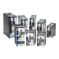
Kollmorgen AKD-x01206 Installation Manual (196 pages)
Brand:
Kollmorgen
| Category:
DC Drives
| Size: 11 MB
Table of Contents
Table of Contents
3
Digital Inputs 3 to
7
2 General
9
2 General
10
1 Table of Contents
10
About this Manual
10
Using the PDF Format
10
Notes for the Printed Edition (Paper Version)
10
Symbols Used
11
Abbreviations Used
12
Standards Used
13
3 Safety
14
You Should Pay Attention to this
15
Use as Directed
17
Prohibited Use
17
Handling
18
Packaging
18
Storage
18
Transport
18
Maintenance and Cleaning
19
Repair and Disposal
19
Uninstalling
19
4 Approvals
20
Conformance with Ul/Cul
21
UL Markings
21
CE Conformance
22
European Directives and Standards for the Machine Builder
23
EC Declaration of Conformity
24
Safe Torque off (STO)
25
5 Package
26
Package Supplied
27
Nameplate
27
Part Number Scheme
28
6 Technical Description and Data
29
The AKD Family of Digital Drives
30
Ambient Conditions, Ventilation, and Mounting Position
32
Mechanical Data
32
Inputs/Outputs
33
Electrical Data AKD-Xzzz06
34
Electrical Data AKD-Xzzz07
35
Performance Data
36
Recommended Tightening Torques
36
Fusing
37
External Power Supply Fusing
37
External 24 V Supply Fusing
37
External Regen Resistor Fusing
37
Grounding System
37
Connectors
38
Cable and Wire Requirements
39
General
39
Cable Cross Sections and Requirements
39
Dynamic Braking
40
Regen Circuit
40
Functional Description
40
Technical Data for AKD-Xzzz06
41
Technical Data for AKD-Xzzz07
42
Switch-On and Switch-Off Behavior
43
Switch-On Behavior in Standard Operation
44
Switch-Off Behavior
45
Switch-Off Behavior Using the DRV.DIS Command
45
Switch-Off Behavior Using a Digital Input (Controlled Stop)
46
Switch-Off Behavior Using HW Enable Input (Uncontrolled Stop)
46
Switch-Off Behavior in the Event of a Fault
47
Stop / Emergency Stop / Emergency off
50
Stop
50
Emergency Stop
51
Emergency off
51
Safe Torque off (STO)
52
Safety Characteristic Data
52
Use as Directed
52
Prohibited Use
52
Safety Instructions
53
Technical Data and Pinning
54
Enclosure, Wiring
54
Functional Description
54
Functional Test
55
Signal Diagram (Sequence)
55
Control Circuit (Example)
56
Mains Supply Circuit (Example)
57
Shock-Hazard Protection
58
Leakage Current
58
Residual Current Protective Device (RCD)
58
Isolating Transformers
58
7 Mechanical Installation
59
Important Notes
60
Guide to Mechanical Installation
60
Mechanical Drawings Standard Width
61
Control Cabinet Layout AKD-Xzzz06, Standard Width
61
Control Cabinet Layout AKD-Xzzz07, Standard Width
62
Dimensions AKD-Xzzz06, Standard Width
63
Dimensions AKD-Xzzz07, Standard Width
64
Mechanical Drawings Extended Width
65
Control Cabinet Layout, Example with AKD-M00306
65
Control Cabinet Layout, Example with AKD-M00307
66
Kollmorgen™ | May
66
Dimensions AKD-Xzzz06, Extended Width
67
Dimensions AKD-Xzzz07, Extended Width
68
8 Electrical Installation
69
Important Notes
70
Guide to Electrical Installation
71
Wiring
72
Components of a Servosystem
73
Connection Overview AKD-B, AKD-P, AKD-T
75
Connector Assignment AKD-X00306, AKD-X00606
75
Connector Assignment AKD-X01206
75
Connector Assignment AKD-X02406 and AKD-Xzzz07
76
Connection Diagram AKD-X00306, AKD-X00606
77
Connection Diagram AKD-X01206
78
Connection Diagram AKD-X02406 and AKD-Xzzz07
79
Connection Overview AKD-M
80
Connector Assignment AKD-M00306, AKD-M00606
80
Connector Assignment AKD-M01206
80
Connector Assignment AKD-M00307, AKD-M00607, AKD-M01207
81
Connection Diagram AKD-M00306, AKD-M00606
82
Connection Diagram AKD-M01206
83
Connection Diagram AKD-M00307, AKD-M00607, AKD-M01207
84
EMI Noise Reduction
85
Recommendations for EMI Noise Reduction
85
Shielding with External Shielding Busbar
86
Shielding Concept
86
Shielding Busbar
87
Shielding Connection to the Drive
88
Grounding Plates
88
Motor Connector X2 with Shielding Connection
88
Shield Connection Clamps
88
Electrical Supply Connection
89
Connection to Various Mains Supply Networks AKD-Xzzz06 (120V to 240V)
89
Connection to Various Mains Supply Networks AKD-Xzzz07 (240V to 480V)
90
Auxiliary Supply (X1)
91
Mains Supply Connection (X3, X4)
92
Three Phase Connection (All AKD Types)
92
Single Phase Connection (AKD-X00306 to AKD-X01206 Only)
93
DC Bus Link (X3)
94
External Regen Resistor (X3)
95
Capacitor Modules (X3)
96
Technical Data
96
Example Installation with KCM-S and KCM-E
97
Example Installation with KCM-P and KCM-E
98
Discharging KCM Modules
99
Motor Connection
100
Motor Power (X2)
101
Cable Length ≤ 25 M
101
Motor Holding Brake (X2)
102
Feedback Connection
103
Feedback Connector (X10)
104
Resolver
105
Sfd
106
Hiperface DSL
107
Encoder with Biss
108
Biss (Mode A) Analog
108
Biss (Mode C) Digital
109
Sine Encoder with Endat
110
Encoder with Endat
111
Sine Encoder with Hiperface
112
Sine Encoder
113
Incremental Encoder
114
Tamagawa Smart Abs Encoder
115
Electronic Gearing, Master-Slave Operation
116
Technical Characteristics and Pinout
116
Connector X7 Input
116
Connector X9 Input
117
Connector X9 Output
117
Command Encoder Signal Connection
118
Incremental Encoder Input 24 V (X7)
118
Incremental Encoder Input 5 V (X9)
118
Encoder with Endat 2.2 Input 5 V (X9)
119
Pulse / Direction Signal Connection
120
Pulse / Direction Input 5 V (X9)
120
Pulse / Direction Input 5V (X7)
120
Up / down Signal Connection
121
Up / down Input 24 V (X7)
121
Up / down Input 5 V (X9)
121
Emulated Encoder Output (EEO)
122
Master-Slave Control
123
I/O Connection
124
I/O Connectors X7 and X8 (All AKD Variants)
124
I/O Connectors X21, X22, X23 and X24 (AKD-T with I/O Option Card Only)
125
I/O Connectors X35 and X36 (AKD-M Only)
127
Analog Input (X8, X24)
128
Analog Output (X8, X23)
129
Digital Inputs (X7/X8)
130
Digital Input 8 (ENABLE)
132
Digital Inputs 1 and
132
Digital Outputs (X7/X8)
133
Digital Outputs 1 and
133
Kollmorgen™ | May
133
FAULT Relay Contacts
134
Digital Inputs with I/O Option (X21, X22)
135
Digital Outputs 21 to 24, 26 to
137
Digital Outputs with I/O Option (X23/X24)
137
Digital Relay Outputs
138
Digital Inputs (X35/X36) with AKD-M
139
Digital Outputs (X35/X36) with AKD-M
141
Digital Outputs 21 and
141
LED Display
142
Rotary Switches (S1, S2, RS1)
143
Rotary Switch RS1 with AKD-M
143
Rotary Switches S1 and S2 with AKD-B, -P, -T
143
Pushbuttons (B1, B2, B3)
144
Pushbutton B1 with AKD-B, -P, -T
144
Pushbuttons B1, B2, B3 with AKD-M
145
SD Card Slot
146
SD Card Slot with I/O Option Card
146
SD Card Slot with AKD-M
147
Service Interface (X11, X32)
148
Pinout
148
Possible Network Configurations
148
Service Bus Protocols
148
Setting the IP Address AKD-B, AKD-P, AKD-T
149
Setting the IP Address AKD-M
151
Modbus TCP
152
CAN-Bus Interface (X12/X13)
152
CAN-Bus Activation with AKD-CC Models
153
Baudrate for CAN-Bus
154
CAN-Bus Cable
155
CAN-Bus Termination
155
Node Address for CAN-Bus
155
CAN-Bus Wiring
156
Motion Bus Interface (X5/X6/X11)
157
Bus Protocols
157
Pinout
157
Ethercat
158
Ethercat Activation with AKD-CC Models
158
Ethernet/Ip
159
Profinet
159
Synqnet
159
9 Setup
160
Important Notes
161
Setup AKD-B, AKD-P, AKD-T
162
Setup Software Workbench
162
Software Description
163
Installation under Windows 2000/XP/VISTA/7
164
Initial Drive Test AKD-B, AKD-P, AKD-T
165
Set IP Address
166
Install and Start Workbench
167
Setup AKD-M
168
Software Description
169
Installation under Windows XP/7
170
Initial Drive Test AKD-M
171
Set IP Address
172
Install and Start KAS IDE
173
Set Drive IP Address in KAS IDE
174
Starting New Project
175
Fault and Warning Messages
178
Additional Fault Messages AKD-T
186
Additional Error and Alarm Messages AKD-M
187
Alarms
189
Troubleshooting the AKD
191
10 Record of Document Revisions
192
11 Index
193
Kollmorgen™ | May
194
Advertisement
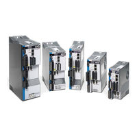
Kollmorgen AKD-x01206 Installation Manual (154 pages)
AKD Series
Brand:
Kollmorgen
| Category:
DC Drives
| Size: 5 MB
Table of Contents
Table of Contents
3
Digital Inputs 3 to
7
1 General
11
About this Manual
12
Target Group
12
Using the PDF Format
12
Abbreviations
13
Warning Symbols
14
Standards Used
15
2 Safety
16
Safety Instructions
17
Use as Directed
18
Prohibited Use
18
3 Approvals
19
Conformance with Ul/Cul
20
UL Markings
20
CE Conformance
22
European Directives and Standards for the Machine Builder
23
EC Declaration of Conformity
24
Safe Torque off (STO)
25
4 Handling
26
Transport
27
Packaging
27
Storage
27
Maintenance and Cleaning
28
Uninstalling
28
Repair and Disposal
28
5 Package
29
Package Supplied
30
Nameplate
30
Part Number Scheme
31
6 Technical Description and Data
32
The AKD Family of Digital Drives
33
Ambient Conditions, Ventilation, and Mounting Position
35
Mechanical Data
35
Inputs/Outputs
36
Electrical Data AKD-Xzzz06
37
Electrical Data AKD-Xzzz07
38
Performance Data
39
Recommended Tightening Torques
39
Fusing
40
External Power Supply Fusing
40
External 24 V Supply Fusing
40
External Brake Resistor Fusing
40
Connectors
41
AKD-Xzzz06 Types (120V to 240V Mains Voltage Supply)
41
AKD-Xzzz07 Types (240V to 480V Mains Voltage Supply)
41
Cable and Wire Requirements
42
General
42
Cable Cross Sections and Requirements
42
LED Display
43
Grounding System
43
Dynamic Braking
44
Functional Description
44
Technical Data for AKD-Xzzz06
45
Technical Data for AKD-Xzzz07
46
Switch-On and Switch-Off Behavior
47
Behavior in Standard Operation
48
Behavior in the Event of a Fault (with Standard Setting)
49
Stop-/Emergency Stop- Function
50
Stop: Standards
50
Emergency Stop: Standards
51
Implementation of the Stop Category
52
Implementation of Stop Category
53
Implementation of Stop Category
54
Kollmorgen | March
54
Safe Torque off (STO)
55
Safety Instructions
56
Use as Directed
56
Prohibited Use
57
Technical Data and Pinning
57
Enclosure
57
Wiring
57
Functional Description (in Process)
58
Signal Diagram (Sequence)
59
Control Circuit (Example)
60
Functional Test
61
Mains Supply Circuit (Example)
61
Shock-Hazard Protection
62
Leakage Current
62
Residual Current Protective Device (RCD)
62
Isolating Transformers
63
7 Mechanical Installation
64
Safety Instructions
65
Guide to Mechanical Installation
65
Control Cabinet Layout AKD-Xzzz06
66
Control Cabinet Layout AKD-Xzzz07
67
Dimensions, AKD-X00306 to X00606
68
Dimensions, AKD-X01206
69
Dimensions, AKD-X02406
70
Dimensions, Akdx00307 to 01207
71
Dimensions, Akdx02407
72
8 Electrical Installation
73
Safety Instructions
74
Guide to Electrical Installation
75
Wiring
76
Components of a Servosystem
77
Connector Assignments, AKD-X00306 to X00606
78
Connector Assignments, AKD-X01206
78
Connector Assignments, AKD-X02406 and AKD-Xzzz07
79
Connection Diagram, AKD-X00306 to X00606
80
Connection Diagram, AKD-X01206
81
Connection Diagram, AKD-X02406 and AKD-Xzzz07
82
EMI Noise Reduction
83
Recommendations for EMI Noise Reduction
83
Shielding with External Shielding Busbar
84
Shielding Concept
84
Shielding Busbar
85
Shielding Connection to the Drive
86
Grounding Plates
86
Shield Connection Clamps
86
Motor Connector X2 with Shielding Connection
87
Electrical Supply Connection
88
Connection to Various Mains Supply Networks AKD-Xzzz06 (120V to 240V)
88
Connection to Various Mains Supply Networks AKD-Xzzz07 (240V to 480V)
89
Auxiliary Supply (X1)
90
Mains Supply Connection (X3, X4)
91
Three Phase Connection (All AKD Types)
91
Single Phase Connection (AKD-Xzzz06 Only)
92
External Brake Resistor (X3)
93
DC Bus Link (X3)
94
Motor Connection
96
Motor Power (X2)
97
Cable Length ≤ 25 M
97
Motor Holding Brake (X2)
98
Feedback Connection
99
Feedback Connector (X10)
100
Resolver
101
Sfd
102
Kollmorgen | March
102
Encoder with Biss
103
Sine Encoder with Endat
104
Encoder with Endat
105
Sine Encoder with Hiperface
106
Sine Encoder with Hall Encoder
107
Incremental Encoder with Hall Switches
108
Encoder Emulation Connector (X9)
109
Input Modes
109
Pinout Input X9
109
Pulse/Direction Input (5 V)
110
Up/Down Input (5 V)
111
Incremental Encoder (a Quad B and Index) Input (5 V)
111
Output Modes
112
Pinout Output X9
112
Emulated Encoder Output (EEO) - a Quad B
113
Master-Slave Control
114
I/O Connection
115
I/O Connectors (X7 and X8)
115
Analog Input (X8)
116
Analog Output (X8)
117
Digital Inputs (X7/X8)
118
Digital Inputs 1 and
120
Digital Input 8 (ENABLE)
120
Digital Outputs (X7/X8)
121
Digital Outputs 1 and
121
FAULT Relay Contacts
122
Service Interface (X11)
123
Possible Network Configurations
123
Setting the IP Address with Rotary Switches
124
Canbus Interface (X12/X13)
125
Transmission Rate for Canbus
125
Node Address for Canbus
126
Canbus Termination
126
CAN Bus Wiring
127
Canbus Cable
128
Motion Bus Interface (X5/X6)
129
Pinout
129
Optional Motion Bus Protocols
129
Ethercat
130
Synqnet (in Process)
130
Motion Busses in Process
130
PROFINET CBA/RT/IRT (in Process)
130
SERCOS III (in Process)
130
Ethernet IP (A-B, in Process)
130
Powerlink (in Process)
130
Modbus TCP/IP (in Process)
130
9 Setup
131
Safety Instructions
132
Setup Software (Workbench)
133
Use as Directed
133
Software Description
134
Hardware Requirements
134
Operating Systems
134
Installation under WINDOWS 2000/XP/VISTA/7
135
Basic Drive Test
136
Unpacking, Mounting, and Wiring the Drive
136
Minimum Wiring for Drive Test Without Load
136
Testing Procedure
137
Confirm Connections
137
Install and Start Workbench
137
Set Drive IP Address in Workbench
138
Enable the Drive Using the Setup Wizard
138
Fault and Warning Messages
139
Kollmorgen | March
139
Troubleshooting the AKD
146
10 Option Cards
147
11 Order Codes
148
Cables, Brake Resistors, Filters, Chokes
148
Drives
148
Mating Connectors
148
AKD-Xzzz06
148
AKD-Xzzz07
148
12 Index
149
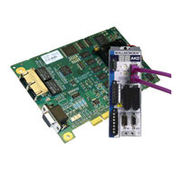
Kollmorgen AKD-x01206 Manual (34 pages)
SynqNet Communication
Brand:
Kollmorgen
| Category:
Servo Drives
| Size: 0 MB
Table of Contents
Table of Contents
3
General
4
About this Manual
5
Target Group
5
Symbols Used
6
Safety
7
Safety Instructions
8
Use as Directed
8
Prohibited Use
8
Important Things to Know
9
Torque Mode Only
9
Wake-And-Shake Support over Synqnet
9
STO State Ignored by "Not Ready for Remote Control" Status Bit
9
Workbench Must Re-Connect after Synqnet Reset
9
Workbench GUI Requires Ethernet Service Port Connection
9
Service Motion Disabled While Synqnet Operational (Cyclic)
9
Fieldbus Fault Cleared Only by Reset
10
Installation and Setup
11
Safety Instructions
12
Synqnet Onboard
13
Synqnet Cables
13
Recommended Synqnet Cabling
13
Synqnet Cable Length
13
LED Functions
14
Synqnet Interconnection
14
String Topology
14
Dual String Topology
15
String and Dual String Topology with Termination
16
Ring Topology
17
AKD Synqnet I/O Mapping
18
General Purpose I/O
18
Dedicated I/O
19
Node I/O
19
Analog Output
20
Analog Input
20
Enable PWM Output on RS485 I/O
21
PWM Parameter Scaling
22
Brake Support for AKD Synqnet
22
AKD-Synqnet Compare FB1.INITSIGNED
23
Synqnet Drive Parameters
24
Synqnet Supported Parameters
24
Advertisement
Advertisement
Related Products
Kollmorgen AKD-x00306
Kollmorgen AKD-x00606
Kollmorgen AKD-x02406
Kollmorgen AKD-x00307
Kollmorgen AKD-x00607
Kollmorgen AKD-x01207
Kollmorgen AKD-x02407
Kollmorgen AKD
Kollmorgen AKD PDMM
Kollmorgen AKD-x04807
Kollmorgen Categories
Servo Drives
Amplifier
Touch terminals
DC Drives
Engine
More Kollmorgen Manuals
Login
Sign In
OR
Sign in with Facebook
Sign in with Google
Upload manual
Upload from disk
Upload from URL