Table of Contents
Advertisement
Advertisement
Table of Contents
Troubleshooting

Related Manuals for Emerson Liebert GXT4


Summary of Contents for Emerson Liebert GXT4
- Page 1 Liebert GXT4 208V, 5000-10,000VA, 6000RTL630 ® ™ User Manual...
-
Page 3: Table Of Contents
TABLE OF CONTENTS ..........1 MPORTANT AFETY NSTRUCTIONS... - Page 4 Shut Down the Liebert GXT4 ..........37 Disconnecting Input Power from the Liebert GXT4....... . 37 Maintenance Bypass .
- Page 5 Figure 11 Rotate the operation and display panel ..........15 Figure 12 External battery cabinets connected to 6000VA Liebert GXT4 ......16 Figure 13 Power distribution box removal from 5000 and 6000VA models .
- Page 6 UPS specifications—Liebert GXT4-6000RTL630 ........
-
Page 7: Important Safety Instructions
Installation instructions and warning notices are in this manual. The Liebert GXT4 208VAC 5000 - 10000 is designed for use with a four-wire input (L1, L2, N, G). The Liebert GXT4-6000RTL630 is designed be used with a three-wire, two-phase utility source (L1, L2, G). - Page 8 Operating this device in a residential area is likely to cause harmful interference that users must correct at their own expense. The Liebert GXT4 series complies with the requirements of EMC Directive 2004/108/EC and the published technical standards. Continued compliance requires installation in accordance with these instructions and use of accessories approved by Emerson.
-
Page 9: Glossary O F Symbols
LOSSARY YMBOLS Risk of electrical shock Indicates caution followed by important instructions AC input AC output Requests the user to consult the manual Indicates the unit contains a valve-regulated lead acid battery PbH2SO4 Recycle DC voltage Equipment grounding conductor Bonded to ground AC voltage WEEE ®... -
Page 10: Product Description
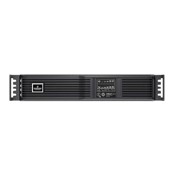
10000VA / 9000W Appearance and Components 1.3.1 Appearance The Liebert GXT4 rack/tower models in various power ratings have the same general appearance, controls and features (see Figure 1). The various rack/tower models differ largely in the type of receptacles each has. ®... -
Page 11: Rear Panel Features
• External Battery Connector • Cooling Fan • Terminal Block Communication • Output Circuit Breakers (on optional PODs) Figure 2 Liebert GXT4 5000VA and 6000VA with input power hard-wired box—rear view USB Port Knockouts for Hard-Wired Liebert Power Input REPO... -
Page 12: Figure 3 Liebert Gxt4-6000Rtl630, Rear View
L6-30P #1 IT Power System Access Cover Maintenance Output Breaker Bypass Breaker for L6-30R #5 Figure 4 Liebert GXT4 8000VA and 10,000VA rear view Liebert Terminal Block IntelliSlot Port REPO Connection Block Communication Maintenance Bypass Switch Cover for Power... -
Page 13: Removable Power Distribution Box
Removable Power Distribution Box The UPS is shipped with a power distribution pack installed. This box contains the UPS input circuit breaker. Figure 5 Power distribution models for 5000VA and 6000VA models of Liebert GXT4 Output Power Breakers Push Button Output Maintenance... -
Page 14: Figure 6 Power Distribution Models For 8000Va And 10,000Va Models Of Liebert Gxt4
Product Description Figure 6 Power distribution models for 8000VA and 10,000VA models of Liebert GXT4 similar features on other distribution boxes arranged differently 5-20R Output Output Circuit Breaker Receptacles Switch for L6-30R Pigtail #1 L6-30ROutput Push Button Receptacles Circuit Breakers... -
Page 15: Figure 7 Power Distribution Models For 8000Va And 10,000Va Models Of Liebert Gxt4 (Continued)
Product Description Figure 7 Power distribution models for 8000VA and 10,000VA models of Liebert GXT4 (continued) PD2-107 PD2-201 Receptacles: four L5-20R; Receptacles: four 5-15R two IEC320-C19 eight IEC320-C13 PD2-108 Receptacles: two L6-30R; two L6-20R PD2-202 Receptacles: (12) IEC320-C13 PD2-109 Receptacles:... -
Page 16: Internal Battery Packs
• The mains power is used as efficiently as possible by the UPS. • The amount of distortion reflected on the mains is reduced. This results in cleaner power being available to other devices in the building not being protected by the Liebert GXT4. ® ™... -
Page 17: Inverter
1.6.7 Internal Bypass The Liebert GXT4 provides an alternate path for mains power to the connected load in the unlikely event of a UPS malfunction. Should the UPS have an overload, overtemperature or any other UPS failure condition, the UPS automatically transfers the connected load to bypass. Bypass operation is indicated by an audible alarm and illuminated amber Bypass LED (other LEDs may be illuminated to indicate the diagnosed problem). -
Page 18: Manual Bypass Mode
NOTICE Risk of loss of power to the connected load. Can cause equipment damage. Turning Off the Liebert GXT4 when it is in Battery Mode will result in loss of output power to the connected load. If the UPS is turned Off manually, it must be manually restarted after mains power returns. -
Page 19: Active Eco Mode
1.7.6 Active ECO Mode All Liebert GXT4 models can operate in Active ECO Mode. In this mode, the connected equipment is powered through the bypass path to increase efficiency, reducing the electrical costs. Active ECO mode keeps the rectifier and inverter operating, allowing the inverter to remain synchronized to bypass. -
Page 20: Installation
Installation Clearances Maintain a clearance of at least 100mm (4 inches) in the front and rear of the Liebert GXT4. Do not obstruct the air inlets on the front panel or rear panel of the UPS—blocking the air inlets reduces ventilation and heat dissipation, shortening the service life of the Liebert GXT4. -
Page 21: Install The Main Cabinet
2. If optional Liebert external battery cabinets will be connected to the Liebert GXT4, take out the spacers shipped with the battery cabinet. 3. Connect the spacers and the support bases as shown in Figure 9. Each Liebert GXT4 needs two assembled support bases, one in the front and one in the rear. -
Page 22: Rack Installation
The Liebert GXT4 UPS and external battery cabinets (EBC), when installed in a rack enclosure, must be supported by a shelf or rack-mount rails. The Liebert GXT4 UPS and EBC units ship with all required hardware to allow rack-mount installation (not included with model numbers that end in “E”). -
Page 23: Connect Input/Output Power
Risk of electric shock. Can cause injury or death. Disconnect all local and remote electric power supplies before working within. Ensure that the Liebert GXT4 is shut down and power has been disconnected before beginning any work on or in the unit. -
Page 24: Remove The Power Distribution Box From 5000 And 6000Va Models
Remove the Power Distribution Cover from 8000 and 10,000VA Models 1. Shut down the Liebert GXT4 (for help, refer to 4.5 - Shut Down the Liebert GXT4). a. From the Main Menu select CONTROL, press Enter, then select TURN ON & OFF. -
Page 25: Install The Power Distribution Box On 5000 And 6000Va Models
Installation Figure 14 Power distribution box removal from 8000 and 10,000VA models Extract screws at these places Pigtails removed for clarity Tabs slip into slots on UPS 2.6.3 Install the Power Distribution Box on 5000 and 6000VA Models 1. Align the connectors and press the power distribution box onto the UPS. 2. -
Page 26: Distribution Box Electrical Connections
8000 and 10,000VA Models Terminal Block Connections Conduit entry holes are provided on the rear and side of the box. Input and output wiring should not share the same conduit. Emerson recommends using strain relief when installing the wire. Table 3 Electrical specifications... -
Page 27: Figure 16 Terminal Block Connections
INPUT NOTE 1. Emerson recommends installing a UL489-approved breaker upstream of unit. 2. The installer must provide circuit breaker protection according to local codes. The utility disconnect should be within sight of the UPS or have appropriate an appropriate lock-out. -
Page 28: Operation And
This chapter describes the Liebert GXT4 controls, particularly the operation and display panel on the front of the Liebert GXT4. The panel has four control buttons, seven LED indicators and a liquid crystal display (LCD), as shown in Figure 17. -
Page 29: Control Buttons
Pressing this button can enter the next level menu or confirm the parameter setting value. The LCD panel shows the UPS status and enables changes to the UPS settings by assisting in navigating through the Liebert GXT4’s menu (see 3.4 - Menu Structure). ®... -
Page 30: Menu Structure
Operation and Display Panel Menu Structure The menu structure of the LCD is shown in Figure 18. Figure 18 Menu structure Audible Alarm Output Startup on Bypass Load Enable Auto Shutdown Status Input Enable Auto Restart Battery Start Windows Frequency Selection Time Since Startup Output Level Selection System... -
Page 31: Startup Screen
Operation and Display Panel 3.4.1 Startup Screen When the Liebert GXT4 is starting up, it initiates a self-test and displays the screen shown in Figure 19 for about 10 seconds. Figure 19 Startup screen EMERSON Network Power After about 10 seconds, the LCD shows one of the On screens in Figure 20; the screen shown depends on whether input power is available. -
Page 32: Default Screen
Operation and Display Panel 3.4.2 Default Screen Press any button in the START SUCCESSFUL screen to enter the default interface, shown in Figure 22. Figure 22 Default screen Values shown will vary GXT4-UPS 3KVA according to installation and configuration. O/P: 230V 50HZ 11.7A I /P: 230V 50HZ 13.1A BATT: 100 % 3MINS LOAD: 100%... -
Page 33: Figure 24 Status Screens
Operation and Display Panel Figure 24 Status screens OUTPUT LOAD INPUT VOLT 120V VOLTAGE 120V FREQ 60 HZ WATT : 1620W FREQUENCY : 60HZ CURR 18.6A 1800VA CURRENT 17.6A POWER : 97KWH POWER : 2112 KWH BATTERY TIME SINCE STARTUP CAPACITY : RUNTIME : 100 MINS... -
Page 34: Figure 26 Ups Screens
Operation and Display Panel UPS Screen Select MAIN MENU > CONFIGURATION > UPS to enter the UPS screen. This menu has six screens, as shown in Figure 26. Figure 26 UPS screens AUDIBLE ALARM STARTUP ON BYPASS GUARANTEE SHUTDOWN ENABLE AUTO RESTART FREQUENCY SELECTION VOLTAGE SELECTION AUTO - BYPASS ENABLE... -
Page 35: Figure 28 Eco Mode Screen
Operation and Display Panel Press the Up or Down button to increase or decrease the value of the settings, and press the Enter button to confirm it. ECO Mode Screens Select MAIN MENU > CONFIGURATION > ECO MODE to enter the ECO MODE screens, as shown in Figure 28. -
Page 36: Figure 30 Language Screen
Select 1 LANGUAGE and press the Enter button to enter the LANGUAGE screen, as shown in Figure 30. The Liebert GXT4 is capable of supporting multiple languages. For the list of supported languages and instructions on how to upload them, refer to the Configuration Program user manual on the included CD. -
Page 37: Figure 33 Control Screen
Operation and Display Panel Control Screen Select Main Menu -> 3 CONTROL to enter the CONTROL screen. This screen has three submenus, as shown in Figure 33. Figure 33 Control screen 1 TURN ON & OFF 2 ALARM CONTROL 3 BATT TEST In the CONTROL screen, press the Up or Down button to move the cursor to the required item, and press the Enter button to enter its submenu. -
Page 38: Figure 36 Batt Test Screen
Operation and Display Panel BATT TEST screen Select MAIN MENU -> 3 CONTROL -> 3 BATT TEST to enter the BATT TEST screen, as shown in Figure 36. Figure 36 Batt Test screen 1 START 2 CANCEL 3 BATT TEST RESULT Log Screen Select MAIN MENU ->... -
Page 39: Figure 39 About Screen
Network Select MAIN MENU>NETWORK to enter the NETWORK screen. The NETWORK screen displays the MAC address and the IPv4 IP address. If the Liebert GXT4 is fitted with an optional Liebert IntelliSlot Web card (Liebert IS-WEBCARD), the screen will display IPv6 IP address settings (IPv6 requires configuration), as shown in Figure 40. -
Page 40: Prompt List
Operation and Display Panel 3.4.4 Prompt List A prompt screen is displayed during the operation of the system to alert you to certain conditions and/or to require your confirmation of a command or other operation. See Table 6 for the system prompts and meanings. -
Page 41: Fault List
Operation and Display Panel 3.4.6 Fault List All UPS fault messages are described in Table 8. Table 8 Fault list Fault Description UPS Self-Test Failed The battery is bad or weak or not connected. UPS Overload The UPS is overloaded. Inverter Out Of Order The inverter has failed. -
Page 42: Operation
UPS and disconnecting mains power from the UPS. NOTE The Liebert GXT4’s battery has been fully charged before delivery, but some charge will be lost during storage and shipping. To ensure that the battery has adequate reserve power to protect the connected load, charge the battery for three hours before putting the UPS into service. -
Page 43: Shut Down The Liebert Gxt4
Disconnecting Input Power from the Liebert GXT4 1. After the UPS has been shut down as detailed in 4.5 - Shut Down the Liebert GXT4, disconnect the input cable from the wall socket. 2. Wait 30 seconds and verify that all indicators have turned Off and the fan has stopped; this indicates that the power-off is complete. -
Page 44: Communication
Follow instructions provided with the Liebert IntelliSlot card to configure Liebert MultiLink , the ® UPS or any additional ancillary product for the Liebert GXT4. These instructions are available at: multilink.liebert.com 5.1.1 Liebert MultiLink Liebert MultiLink monitors the UPS continuously and can shut down the computer or server in the event of an extended power failure. -
Page 45: Usb Port Communication
A standard B-type USB port is provided to allow connection to a computer or network server. The USB port can be used to communicate with the Liebert GXT4 configuration program (see section 5.2.1 for details) or Liebert MultiLink (refer to 5.1.1 - Liebert MultiLink for description) that is provided on the CD that is included with the UPS. -
Page 46: Terminal Block Communication
When the Auto-Enable output option is selected and the UPS output is disabled using Pin 1 and Pin 2, the Liebert GXT4’s output can turn On automatically and without warning if the Pin 1 and Pin 2 connection is changed. -
Page 47: Battery Mode Shutdown
This timer cannot be stopped once triggered. If the mains power returns during this countdown, the Liebert GXT4 will still shut down and must remain shut down for 10 seconds. Whether the UPS turns back On when the power is restored depends on the auto-restart setting. -
Page 48: Remote Emergency Power Off
Communication Remote Emergency Power Off The UPS is equipped with a Remote Emergency Power Off (REPO) connector. The user must supply a means of interfacing with the REPO circuit to allow disconnecting the UPS input feeder breaker to remove all sources of power to the UPS and connected equipment to comply with national and local wiring codes and regulations. -
Page 49: Maintenance
UPS functions. Replacing the Internal Battery Pack The Liebert GXT4 is designed to allow the user to replace the internal battery pack safely. Refer to Table 10 for internal battery pack part numbers for Liebert GXT4 UPS. -
Page 50: Battery Replacement Procedures
Maintenance 6.1.1 Battery Replacement Procedures 1. Gently remove the front plastic bezel cover from the UPS. 2. Loosen and remove the six screws on the battery door, as shown in Figure 42. 3. Lay the battery door and screws aside for reassembly. Figure 42 Removing the front plastic bezel cover and battery door Battery Door Screws, 6... -
Page 51: Battery Charging
The Liebert GXT4 charges the batteries continuously when it is connected to the utility input power. If the Liebert GXT4 will be stored for a long time, Emerson recommends connecting the UPS to input power for at least 24 hours every four to six months to ensure full recharge of the batteries. -
Page 52: Checking Ups Status
• Check whether the UPS is faulty: Is the Fault Indicator on? Is the UPS sounding an alarm? • Check whether the UPS is operating in Bypass Mode. Normally, the UPS operates in Normal Mode. If it is operating in Bypass Mode, stop and contact your local Emerson representative, or Emerson Channel Support. -
Page 53: Figure 45 Removing Power Module From Liebert Gxt4 8000 And 10,000Va Models
Maintenance Figure 45 Removing power module from Liebert GXT4 8000 and 10,000VA models Power module pulled part of the way out of an 8000 or 10,000VA unit 11. Insert the replacement UPS power module. 12. Slide the power module restraint lever back into the locked position. -
Page 54: Troubleshooting
UPS Symptoms The following symptoms indicate the Liebert GXT4 is malfunctioning: • The relative indicators illuminate, indicating the UPS has detected a problem. • An alarm buzzer sounds, alerting the user that the UPS requires attention. -
Page 55: Audible Alarm
When reporting a UPS issue to Emerson, include the UPS model and serial number. These are located in several places for your ease of location: on the top panel (rack mount orientation); the left side (tower orientation);... -
Page 56: Specifications
Specifications PECIFICATIONS Table 14 UPS specifications—5000, 6000, 8000 and 10,000 models Model Number GXT4-5000RT208 GXT4-6000RT208 GXT4-8000RT208 GXT4-10000RT208 Model Rating 4000W/5000VA 4800W/6000VA 7200W/8000VA 9000W/10000VA Dimensions, Rack Mount, W x D x H Unit, in. (mm) 16.9 x 26.1 x 6.8 (430 x 662 x 173) 16.9 x 26.5 x 10.3 (430 x 672 x 261) Shipping, in. -
Page 57: Table 15 Ups Specifications-Liebert Gxt4-6000Rtl630
Specifications Table 15 UPS specifications—Liebert GXT4-6000RTL630 Model Number GXT4-6000RTL630 Model Rating 4200W/6000VA Dimensions, Rack Mount, W X D X H, in. (mm) Unit 16.9 x 22.6 x 8.5 (430 x 574 x 217) Shipping 20.3 x 29.3 x 20.9 (516 x 745 x 530) -
Page 58: Table 16 Internal Battery Cabinet Specifications
Specifications Table 16 Internal battery cabinet specifications GXT4-144VBATKIT GXT4-240VBATKIT GXT4-288VBATKIT Model Number GXT4-5000RT208 GXT4-8000RT208 GXT4-6000RTL630 GXT4-6000RT208 GXT4-10000RT208 Used with UPS Model Dimensions, Rack Mount, W x D x H, in (mm) 8.1 x 19.3 x 2.8 7.2 x 15.4 x 4.4 8.1 x 19.7 x 5.3 Unit (206 x 490 x 70) -
Page 59: Gxt4-6000Rtl630
Specifications Table 17 External battery cabinet specifications Model Number GXT4-144VBATT GXT4-240VBATT GXT4-288VBATT GXT4-5000 & GXT4-8000 & Used w/UPS Model GXT4-6000RT208 GXT4-6000RTL630 GXT4-10000RT208 Dimensions, W x D x H, in. (mm) 16.9 x 26.1 x 3.3 16.9 x 22.6 x 6.8 16.9 x 26.5 x 6.8 Unit (with bezel) (430 x 662 x 85) -
Page 60: Table 19 Power Distribution Box Specifications For Gxt4-8000Rt208 And Gxt4-10000Rt208
Specifications Table 19 Power distribution box specifications for GXT4-8000RT208 and GXT4-10000RT208 Power Distribution Box Model # POD Model # PD2-101 PD2-102 PD2-103 PD2-104 PD2-105 PD2-106 Dimensions, W x D x H, in. (mm) Unit 7.4 x 5.7 (188 x 145) Shipping 11.9 x 20.6 x 8.7 (302 x 522 x 220) Weight, lb (kg) -
Page 61: Table 21 Battery Run Time, Minutes
Specifications Table 21 Battery run time, minutes 208/120 VAC RT Models 208 VAC RT Model Number of External Load Percent Battery Cabinets of Capacity 5 kVA 6 kVA 8 kVA 10 kVA 6 kVA (L630) Internal Battery 100% Internal Battery + 1 External Battery Cabinet 100%... - Page 62 Specifications Table 21 Battery run time, minutes 208/120 VAC RT Models 208 VAC RT Model Number of External Load Percent Battery Cabinets of Capacity 5 kVA 6 kVA 8 kVA 10 kVA 6 kVA (L630) Internal Battery + 4 External Battery Cabinets 100% Internal Battery...
-
Page 63: Auto-Learning Battery Run Times
Specifications Auto-Learning Battery Run Times As batteries age, the estimated run times may become less accurate. The Liebert GXT4 is programmed to “learn” from a full battery discharge and modify the estimated run time for the measured battery capacity. This can improve accuracy and compensate for aging batteries or batteries that operate at different ambient temperatures. - Page 64 Philippines ® Liebert is a registered trademark of Liebert Corporation. +63 2 687 6615 All names referred to are trademarks Fax: +63 2 730 9572 or registered trademarks of their respective owners. SL-23194_REV0_10-14 Emerson Network Power Liebert www.emerson.com...
Need help?
Do you have a question about the Liebert GXT4 and is the answer not in the manual?
Questions and answers
No enciende
The Emerson Liebert GXT4 may not turn on due to the following reasons:
1. The internal battery is not connected.
Solution: Connect the internal battery and try to start the unit.
2. The batteries are not charged enough or not connected.
Solution: Leave the UPS connected to input power for 24 hours to recharge the batteries, then try to start the unit.
3. The UPS is not plugged in securely.
Solution: Ensure the UPS is securely plugged into the wall receptacle.
4. The UPS input protection fuse has blown/opened.
Solution: Replace the UPS input fuse and restart the UPS.
If the issue persists after these steps, contact Emerson Channel Support.
This answer is automatically generated