Sign In
Upload
Manuals
Brands
Skyjack Manuals
Boom Lifts
SJ-7027
Skyjack SJ-7027 Manuals
Manuals and User Guides for Skyjack SJ-7027. We have
1
Skyjack SJ-7027 manual available for free PDF download: Operating, Maintenance And Parts Manual
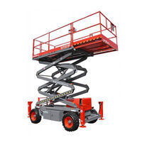
Skyjack SJ-7027 Operating, Maintenance And Parts Manual (217 pages)
SJ-600 Series
Brand:
Skyjack
| Category:
Boom Lifts
| Size: 8.09 MB
Table of Contents
Serial Number Breakdown
2
Table of Contents
3
Purpose of Equipment
7
Use of Equipment
7
Warnings
7
Lifting Mechanism
7
Section 1 - Introduction
7
Description
7
Operator Warnings
8
Specifications and Features
9
Standard Features and Optional Equipment
10
Work Platform Major Component Identification
11
SKYJACK SJ-600 Series Work Platform
11
Section 2 - Operation
12
Engine Control Panel (Diesel)
13
Engine Control Panel (Dual Fuel)
13
Operator’s Control Box
14
Platform Controls
14
1500W AC Inverter (Option)
15
Hydraulic Generator Control (Option)
15
Powered Extension Platform Control Box (Option)
15
Base Controls - Manual Safety Bar
16
Fold-Down Guardrail System
16
Identification and Operation of Safety Devices
16
Operating Controls Identification
12
Base Controls
12
Electrical Panel
12
Operating Procedures
17
Set-Up Procedure
17
Using the Engine Controls on the Engine
17
Operator's Checklist
18
Prestart Checks
18
Operator Qualifications
19
Start and Operation
19
To Drive Forward or in Reverse
19
Shutdown Procedure
20
Emergency Lowering System
21
Electrical Inverter (Option)
22
Hydraulic Generator (Option)
22
Winching and Towing Procedures
22
Maximum Platform Capacities (600 Series)(Evenly Distributed)
24
Tire Specifications
24
Maintenance and Inspection Schedule
25
Control Box Reference Table
26
Electrical Schematic Reference Table
26
Panel Diagram Reference Table
26
Section 3 - Systems Component Identification and Schematics
26
Table of Contents
26
Relay Terminal and Function Chart
27
Electrical Symbol Chart
28
Hydraulic Symbol Chart
29
Hydraulic Schematic
31
Hydraulic Schematic Parts List
32
Auto-Reset Brake Manifold
33
Hydraulic Manifold Component and Port Identification
33
Main Manifold
33
Quick Brake Manifold
33
Operator's Control Box Diagram
34
Basi Control/Electrical Panel Diagram (ANSI/SIA and CSA Machines with Serial Number 30985 and Below)
54
Basi Control/Electrical Panel Diagram (ANSI/SIA and CSA Machines with Serial Number 30986 through 32097)
55
Basi Control/Electrical Panel Diagram (ANSI/SIA and CSA Machines with Serial Number 32098 and Above)
56
Basi Control/Electrical Panel Diagram (CE Machines with Serial Number 30985 and Below)
57
Basi Control/Electrical Panel Diagram (CE Machines with Serial Number 30986 through 32097)
58
Basi Control/Electrical Panel Diagram (CE Machines with Serial Number 32098 and Above)
59
Electrical Inverter Diagram
60
Electrical Schematic (Machines Equipped with Kubota Dual Fuel Engine and Shown with ANSI/SIA and CSA Options)
61
System Component Identification and Schematics Addendum
68
Revised Schematic
70
Troubleshooting Information
72
Section 4 - Troubleshooting Information
72
Section 5 - Maintenance and Service
89
Table of Contents
89
Operators Responsibility for Maintenance
90
General Maintenance Hints
90
Maintenance and Inspection Schedule
90
Owners Annual Inspection Record
90
Hydraulic System and Component Maintenance and Repair
91
General Specifications - SJ-600 Series
92
Torque Specifications
93
Brake Adjustment Procedure
94
Plug Removal and Replacement
94
Disc Parking Brake
94
System and Lift Pressure Adjustments
96
Speed Motor Assembly
97
Wheel Bolt/Nut Inspection and Torquing Procedure
98
Parts List
99
Section 6 - Parts Lists
100
List of Illustrations
100
Figure 6-1. Main Platform and Railings
102
Figure 6-2. Roll-Out Extension Platform Assembly
105
Figure 6-3. Powered Extension Platform Assembly
107
Powered Extension Platform Control Box Assembly
110
Powered Extension Platform Cylinder Assembly
111
Powered Extension Platform Electrical Panel
112
Powered Extension Platform Hydraulic Hose Connections
113
Figure 6-8A. Control Box Assembly (Serial # 33189 and Above)
114
Figure 6-8B. Control Box Assembly (Serial # 33188 and Below)
117
Figure 6-9A. Drive/Steer Controller Assembly (Serial # 33189 and Above)
121
Drive/Steer Controller Assembly (Used on Machines with Serial Numbers 33188 and Below)
123
Figure 6-10. Scissor Arm Assembly
124
Figure 6-11. Lift Cylinder Assembly
128
Scissor Arm Hydraulic Hose Connections
130
Figure 6-13. Base, Axles, and Wheels
131
Figure 6-20. Front Idle Axle Assembly (for 2-Wheel Drive Machines)
144
Front Axle Hardware Assembly (4Wd)
146
Front Axle Assembly (4WD)
148
Base Hydraulic Hose Connections
133
Disc Brake Assembly
139
Disc Brake Cylinder Assembly
141
Steer Cylinder Assembly
142
Figure 6-23A. Center Drive and Drive Shafts (Haessler Drive Serial #1691 and Above)
151
Figure 6-23B. Center Drive and Drive Shafts (Haessler Drive Serial #1690 and Below)
153
Figure 6-24. Center Drive and Drive Shafts (Serial # 32272 and Below)
155
Figure 6-25. Rear Drive Axle Assembly
158
Figure 6-28. Fuel Tank Assembly - Diesel Engines
162
Hydraulic Oil Tank Assembly (Serial # 30200 and Above)
164
Hydraulic Oil Tank Assembly (Serial # 30199 and Below)
165
Figure 6-31. Hydraulic/Electric Cabinet Assembly
166
Hydraulic/Electric Cabinet Hydraulic Hose Connections (Machines with Serial # 30167 and Above)
169
Hydraulic/Electric Cabinet Hydraulic Hose Connections
170
Auto Reset Brake Manifold Assembly (Machines with Serial # 30167 & Above)
171
Quick Brake Manifold Assembly (Machines with Serial # 30166 & Below)
172
Figure 6-36. Main Manifold Assembly (Serial # 30208 and Above)
173
Main Manifold Assembly (Machines with Serial # 30207 and Below)
175
Cushion Cylinder Assembly
177
Figure 6-39 Motion Control Valve Assembly
178
Figure 6-40. Base Control/Electrical Panel Assembly (Serial # 30986 and Above)
179
Base Control/Electrical Panel Assembly (Machines with Serial # 30985 & Below)
181
Engine Roll-Out Tray Assembly (Machines with Serial # 30419 and Above)
184
Engine Roll-Out Tray Assembly (Machines with Serial # 30418 and Below)
186
Engine Control Panel - Kubota Dual Fuel (Serial # 31802 and Above)
188
Engine Control Panel - Kubota Gasoline/Dual Fuel Engines
189
Engine Control Panel - Kubota Diesel Engine
190
Fuel Tank/Hydraulic Oil Tank Cabinet Assembly
160
Fuel Tank Assembly - Gasoline Engines
161
Figure 6-47. Engine and Related Parts - Kubota Dual Fuel Engine
191
Figure 6-48. Engine and Related Parts - Kubota Gasoline Engine
194
Figure 6-49. Propane Tank Mounting and Connection
197
Figure 6-50. Dual Fuel System - Kubota Gasoline Engine
199
Figure 6-51. Engine and Related Parts - Kubota Diesel Engine (Serial # 31252 and Above)
201
Engine and Related Parts - Kubota Diesel Engine(Serial Number 31251 and Below)
203
Base Control Box Option
205
AC Outlet on Platform Option
206
3500 Watt Hydraulic Generator Option - Generator, Oil Cooler, and Mounting
207
3500 Watt Hydraulic Generator Option - Hydraulic Hose Connections
208
Figure 6-57. Scissor Guard Option
209
Figure 6-58. Labels and Nameplates
211
Advertisement
Advertisement
Related Products
Skyjack SJ 7135
Skyjack SJ 7127
SKYJACK SJKB-33i
Skyjack SJ 4626
Skyjack SJ 3226
Skyjack SJ 3215
Skyjack SJ 8841
Skyjack SJ1056 THS
Skyjack SJ1256 THS
Skyjack SJ 46AJ
Skyjack Categories
Lifting Systems
Boom Lifts
Scissor Lifts
Forklifts
Battery Charger
More Skyjack Manuals
Login
Sign In
OR
Sign in with Facebook
Sign in with Google
Upload manual
Upload from disk
Upload from URL